WEEK 9 INPUT DEVICES
INTRODUCTION
This week's assignment is Input Devices. The goal is to design, assembly, and program sensors or other components that provide signals to the PCB we fabricated in previous weeks so the microcontroller can process that data.
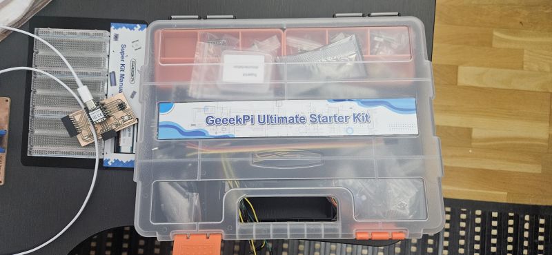
The completion of this assignment faced a significant setback: the CNC milling machine we use for PCBs broke down. Consequently, we couldn't mill the specific modules to connect our sensors to the main PCB. As a workaround, we used commercial sensor modules. Specifically, I used components from the GeeekPi Ultimate Starter Kit, which is quite comprehensive.
SCHEDULE
This has been an unusual week. Since we couldn't use the milling machine, the process felt somewhat simpler, yet it provided a great opportunity to study off-the-shelf components and understand how commercial modules are designed in the real world. For this assignment, I focused on the temperature sensor, though I plan to integrate the rest of our sensors in the coming weeks.
Regarding my schedule, time constraints mean I have to condense most of the assignment work into the weekend—specifically Saturday afternoons and Sundays, after attending to other responsibilities. My strategy is to use the limited time I have during the week to review previous assignments and address any feedback or potential fixes identified by my instructors.
- On Friday after work, between 9:00 PM and midnight, I studied the temperature sensor's datasheet and understood its routing. I then connected the sensor to my PCB and tested several Arduino sketches to get it running. Before calling it a night, I successfully got the sensor working and verified the temperature readings in the serial monitor.
- On Saturday afternoon, I began the documentation process, detailing every aspect of the assignment.
- Sunday was fully dedicated to finishing the documentation, preparing the photos and videos, and assembling the website.
As in other weeks, the work is divided into two parts
GROUP ASSIGNMENT
FabLab Leon work groupThe original task was to study different sensors and design the necessary modules to interface them with our PCB. Due to the lack of a milling machine, we shifted our focus to analyzing commercial modules to understand their internal circuitry, logic, and how to correctly interface them with our boards.
Temperature Sensor Study
I chose the temperature sensor for my analysis.
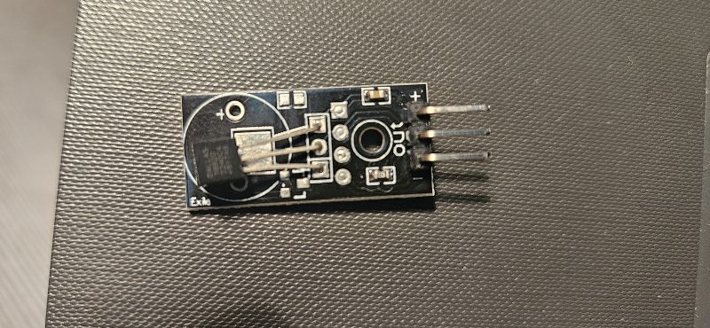
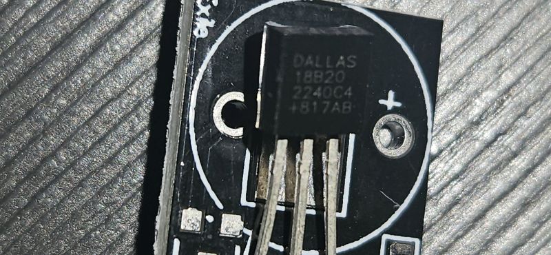
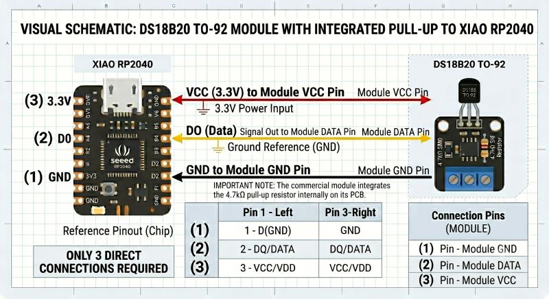
By inspecting the sensor and its markings, I identified it as a DS18B20 (Digital 1-Wire Temperature Sensor) mounted on a breakout board. The module includes a 4.7kΩ pull-up resistor, essential for the 1-Wire protocol.
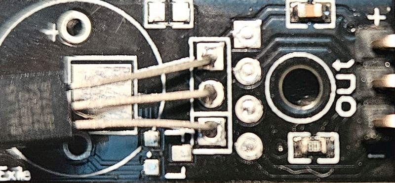
Trace Analysis:
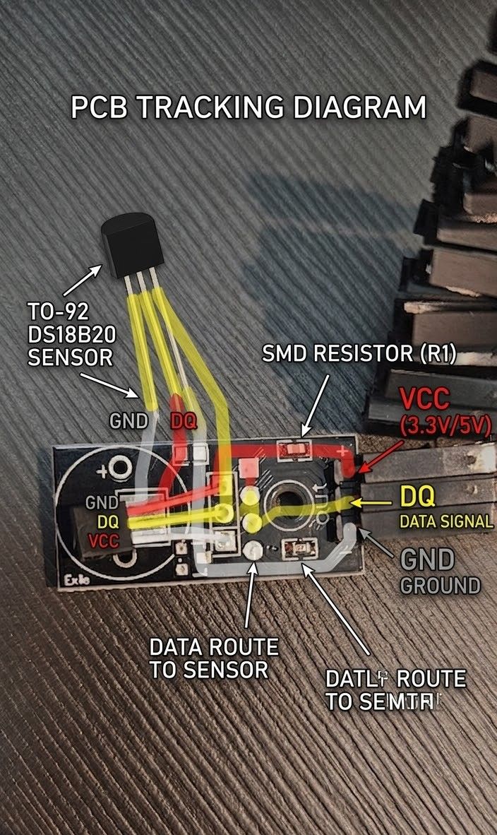
- Red (VCC): Connects the '+' pin of the header directly to the right pin of the sensor (VCC) and one side of the SMD resistor.
- Yellow (DQ/Data): The signal trace. It connects the central 'out' pin to the sensor's center pin (DQ) and the other side of the SMD resistor, completing the pull-up circuit.
- Grey/White (GND): Connects the '-' pin to the left pin of the sensor (GND).
Technical Specifications (DS18B20):
- Protocol: 1-Wire®. To read the data, the code must first "search" for the sensor's unique 64-bit address on the bus. This allows multiple sensors to share a single data line.
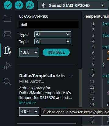
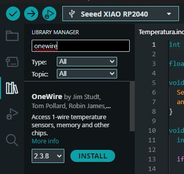
- Libraries: For the Arduino IDE, the DallasTemperature and OneWire libraries are required.
- Operating Voltage: 3.3V to 5V.
- Range: -55°C to +125°C with ±0.5°C accuracy.
Important note: As seen in the technical specifications, to get this sensor running in the Arduino IDE, we must install two specific libraries: DallasTemperature and OneWire.
Both can be easily found and installed via the Library Manager in the Arduino IDE.
(DS18B20) Temperature Module: Voltage Behavior Explanation
For the DS18B20 temperature module, the way voltage varies across its terminals is unique compared to traditional analog sensors (such as an NTC thermistor or an LM35 linear sensor).
Because it is a fully digital 1-Wire sensor, temperature is not translated into a continuous analog voltage level. Instead, it is converted into a structured stream of binary data. Below is a detailed breakdown of how the voltage behaves on each of its three pins:
1. Power Supply Pins (VCC & GND)
- Behavior: The voltage remains strictly constant.
- Details: The
VCCpin stays fixed at the stable3.3Vprovided by the XIAO RP2040, and theGNDpin remains at0V. There is absolutely no voltage variation on these power lines when the ambient temperature changes.
2. Data Pin (DQ / DATA)
This pin handles all the operations. Its voltage behavior transitions dynamically between two fundamental communication states:
- Idle State (High Impedance): When the sensor is not actively communicating with the microcontroller, the data line is pulled up and remains fixed at 3.3V. This is maintained by the
4.7Kpull-up resistor integrated onto the commercial module's PCB. - Active State (Data Transmission): When the XIAO RP2040 requests a temperature reading, the data line rapidly toggles between 0V and 3.3V, establishing a high-speed square wave (digital pulses representing 0s and 1s).
How does temperature affect this voltage?
The temperature does not alter the voltage amplitude (which always swings exactly between 0V and 3.3V). Instead, it modifies the specific binary pulse train being transmitted.
Internal Conversion and Protocol Mechanism
- The DS18B20 incorporates an internal 12-bit Analog-to-Digital Converter (ADC).
- As the ambient temperature changes, the internal logic computes a corresponding binary value (e.g.,
000000101000for 40°C). - During the transmission phase, the voltage on the
DQpin drops to 0V and returns to 3.3V following the timing sequence of that specific digital code.
If you measure the data pin with a conventional digital multimeter, you will read a near-constant value close to 3.3V because the communication windows are extremely short. To visually observe how voltage varies as a function of temperature, an oscilloscope or a logic analyzer is required. Under inspection, you will see that the arrangement, structure, and width of the 0V and 3.3V timing slots shift dynamically to encode the updated temperature reading.
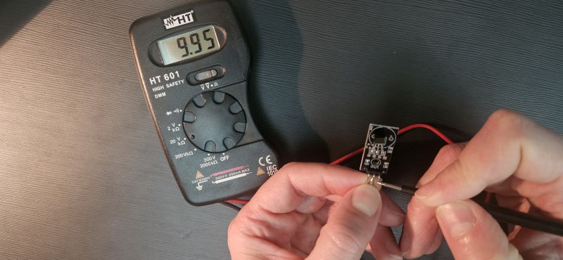
Hardware Verification:
Using a multimeter to measure resistance between the pins, I found a 10kΩ resistance between VCC and Out. Although the standard is 4.7kΩ, the manufacturer likely used 10kΩ for cost-efficiency or extra protection; the sensor still functions correctly. I also spotted a decoupling capacitor between VCC and GND to filter power noise.
INDIVIDUAL ASSIGNMENT
Once I understood the sensor's hardware logic, I proceeded to integrate it with my PCB.
Wiring and Pinout
I connected the sensor to my board following the mapping identified in the Group assignment:
- Red -> 3.3V
- Grey -> GND
- Yellow -> Digital Input (D0)
Programming and Troubleshooting
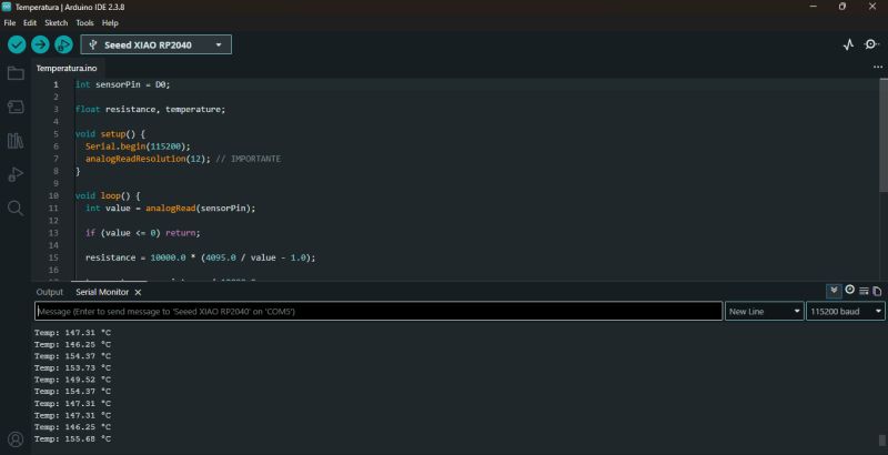
I initially asked ChatGPT for a base code, but it failed. It provided a script treating the DS18B20 as an analog sensor, resulting in nonsensical readings (e.g., reporting 150°C at room temperature).
ChatGPT failed
          int sensorPin = D0;

float resistance, temperature;

void setup() {
  Serial.begin(115200);
  analogReadResolution(12); // IMPORTANTE
}

void loop() {
  int value = analogRead(sensorPin);

  if (value = 0) return;

  resistance = 10000.0 * (4095.0 / value - 1.0);

  temperature = resistance / 10000.0;
  temperature = log(temperature);
  temperature /= 3950;
  temperature += 1.0 / (25 + 273.15);
  temperature = 1.0 / temperature;
  temperature -= 273.15;

  Serial.print("Temp: ");
  Serial.print(temperature);
  Serial.println(" °C");

  delay(500);
}
I then switched to Gemini. I explained I was doing the FabAcademy, provided photos of my RP2040-based PCB and the sensor, and it generated a much more accurate code. However, there was a subtle but critical mapping error:
Gemini also fails
          #include OneWire.h
#include DallasTemperature.h

// Define el pin donde conectaste el "out" del sensor
const int BUS_ONE_WIRE = 0; // Cambia a 1, 2, etc., según tu PCB

OneWire oneWire(BUS_ONE_WIRE);
DallasTemperature sensors(&oneWire);

void setup() {
  Serial.begin(115200);
  // Esperar a que el puerto serie esté listo (importante en el RP2040)
  while(!Serial);

  Serial.println("--- Buscando Sensor DS18B20 ---");
  sensors.begin();

  // Verificar cuántos sensores hay en el bus
  int count = sensors.getDeviceCount();
  Serial.print("Sensores detectados: ");
  Serial.println(count);
}

void loop() {
  Serial.print("Leyendo temperatura... ");
  sensors.requestTemperatures(); // Envía el comando para leer

  float tempC = sensors.getTempCByIndex(0); // Lee el primer sensor

  if(tempC != DEVICE_DISCONNECTED_C) {
    Serial.print(tempC);
    Serial.println(" °C");
  } else {
    Serial.println("Error: Sensor no encontrado");
  }

  delay(2000); // El DS18B20 es lento, no satures el bus
}
The Pin Mapping Trap: The code referenced pin 0 instead of D0. In the Seeed XIAO RP2040 ecosystem, GPIO 0 (internal chip numbering) corresponds to physical pin D6, not D0.
Coincidentally, my PCB has an LED connected to D6. When I ran the code, the sensor wasn't found, and the LED started blinking mysteriously—the 1-Wire protocol was trying to communicate through the LED!

Once I corrected the pin assignment to the proper XIAO alias, it worked perfectly.
Final Code Logic
To add a functional layer, I modified the code to use the onboard LED as an alarm: if the temperature exceeds 30°C, the LED blinks.
Final Code
          #include OneWire.h
#include DallasTemperature.h

// Configuración de Pines
const int BUS_ONE_WIRE = D0;  // Pin del sensor DS18B20
const int LED_ALERTA = D6;    // Tu LED en la PCB

// Umbral de temperatura (ajústalo según el calor de tu mano)
const float UMBRAL_CALOR = 30.5;

OneWire oneWire(BUS_ONE_WIRE);
DallasTemperature sensors(&oneWire);

void setup() {
  Serial.begin(115200);
  while(!Serial); // Espera a que abras el monitor serie

  pinMode(LED_ALERTA, OUTPUT);
  sensors.begin();

  Serial.println("--- Sistema de Alerta Térmica Iniciado ---");
  Serial.print("Umbral configurado: ");
  Serial.print(UMBRAL_CALOR);
  Serial.println(" ºC");
}

void loop() {
  sensors.requestTemperatures();
  float tempC = sensors.getTempCByIndex(0);

  if(tempC != DEVICE_DISCONNECTED_C) {
    Serial.print("Temperatura: ");
    Serial.print(tempC);
    Serial.println(" ºC");

    // Lógica del LED
    if(tempC > UMBRAL_CALOR) {
      // Si hace calor, el LED parpadea rápido
      digitalWrite(LED_ALERTA, HIGH);
      delay(100);
      digitalWrite(LED_ALERTA, LOW);
      delay(100);
    } else {
      // Si está frío, el LED se queda apagado
      digitalWrite(LED_ALERTA, LOW);
    }
  } else {
    Serial.println("Error: Sensor desconectado");
    // Parpadeo lento de error para avisarte visualmente
    digitalWrite(LED_ALERTA, HIGH);
    delay(1000);
    digitalWrite(LED_ALERTA, LOW);
    delay(1000);
  }

  // Pequeña pausa para no saturar el bus 1-Wire
  delay(500);
}
AI Collaboration & Code Generation Insights
To obtain the Arduino code shared above, I collaborated with AI, specifically using Gemini. However, there is no single, specific prompt used to generate the code. Instead, the process relies on an ongoing, natural dialogue where I explain the logical ideas and specific tasks I want the microcontroller to execute.
Furthermore, with the memory and past activity features enabled, Gemini retains the context of previous project developments and adapts to my workflow preferences. As a result, the AI often anticipates my technical requirements, occasionally proposing relevant code structures even before they are explicitly requested.
Logic Analyzer
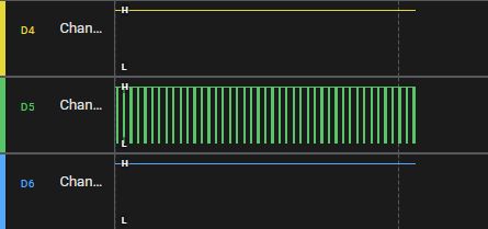
Finally, we used a logic analyzer to observe the sensor's operation and, more importantly, the behavior of the 1-Wire protocol. We observed how the system constantly sends out pulses to 'handshake' with any connected sensors and retrieve their readings.
It was interesting to see how the data is transmitted in pulses and how the pulse patterns change according to the temperature data being transmitted.
CONCLUSION
The key takeaway from this assignment is the importance of pinout verification. You must clearly understand the relationship between the microcontroller's internal GPIO and the breakout board's physical pins (like the Seeed XIAO). Additionally, analyzing the module's traces is vital to ensure you aren't missing required components like pull-up resistors or filter capacitors.