WEEK 7 COMPUTER-CONTROLLED MACHINING
INTRODUCTION
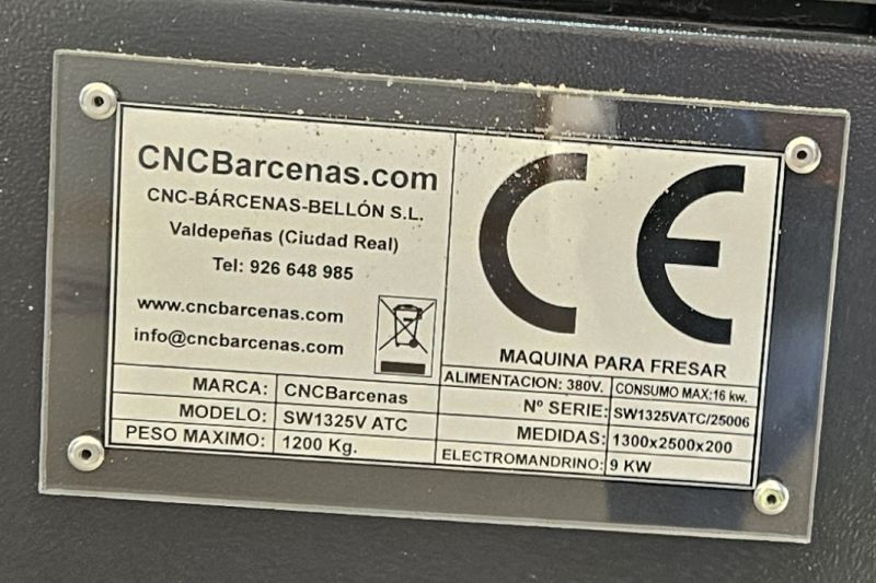
For this week, the assignment consists of designing an object and manufacturing it using the CNC milling machine, specifically, a SW1325V/ATC CNC BARCENAS. The most important aspect of this week, as our instructors reminded us, is safety, since this is the largest and most powerful machine we will use during the course.
It is worth mentioning that in this assignment I feel more comfortable, since I previously worked with milling machines and lathes. However, at that time they were not CNC-controlled, or the control systems were very rudimentary, as we are talking about more than 20 years ago. Nevertheless, the safety measures and the general way of working with the machine remain the same.
As in previous weeks, my biggest challenge is lack of time and unfamiliarity with the software we are going to use. Without a doubt, my biggest headache is still FreeCAD, which I have not yet fully mastered. Even so, on Friday night I was able to create a small design to cut the next morning in the lab.
SCHEDULE
The time distribution this week was similar to previous ones:
- Wednesday night: after dinner I reviewed details from previous assignments, since there are still some small issues I want to finish, such as poorly aligned photos or comments that I have not yet written.
- Thursday: while having lunch in a restaurant I watched about half an hour of the Wednesday lecture recording, finishing it in the afternoon just before starting the explanation videoconference with my instructors.
- Friday night: I worked on the design.
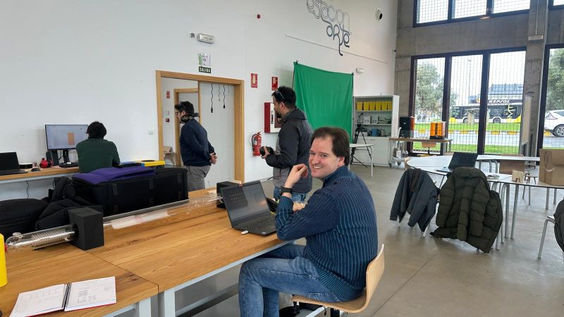
- Saturday morning: I went to the FabLab with my instructors to prepare and cut the designs that my two classmates and I had created. Later in the evening I started the documentation.
- Sunday afternoon: after working on the documentation until 4:00 a.m., I dedicated the afternoon to translating the texts from Spanish to English and preparing the webpage, adjusting photos and videos and placing everything into the HTML code, which I am gradually becoming more comfortable with.
As in other weeks, the work is divided into two parts
GROUP ASSIGNMENT
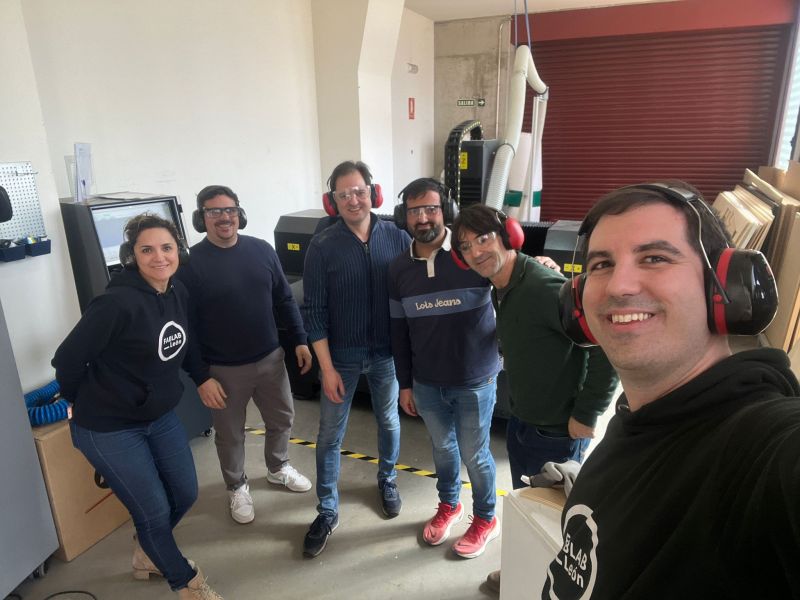
FabLab Leon work groupSafety measures
The group assignment consisted of describing the safety measures and documenting the CNC training session given by Javier Bayón at FabLab Ponferrada.
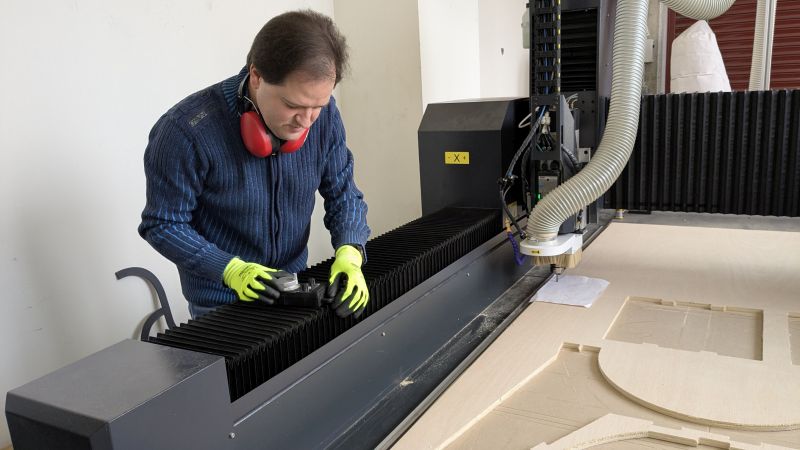
The most important aspect when working with this machine is the use of PPE (Personal Protective Equipment)
- Gloves when handling wood, due to the risk of cuts or splinters.
- Safety glasses when the milling bit is cutting, to protect from possible fragments that may be ejected.
- Hearing protection, due to the noise level generated by the machine during operation.
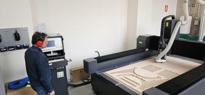
And most importantly, never get too close to the machine while it is operating
In addition, it is necessary to follow certain routines when starting and finishing work.
Before starting
- Check the general condition of the machine: connections, tubes, chip bags, bed cleanliness, etc.
- Check oil levels if necessary and the condition of the compressed air condensate tanks.
- Perform a movement test to verify that the machine moves correctly without any problems.
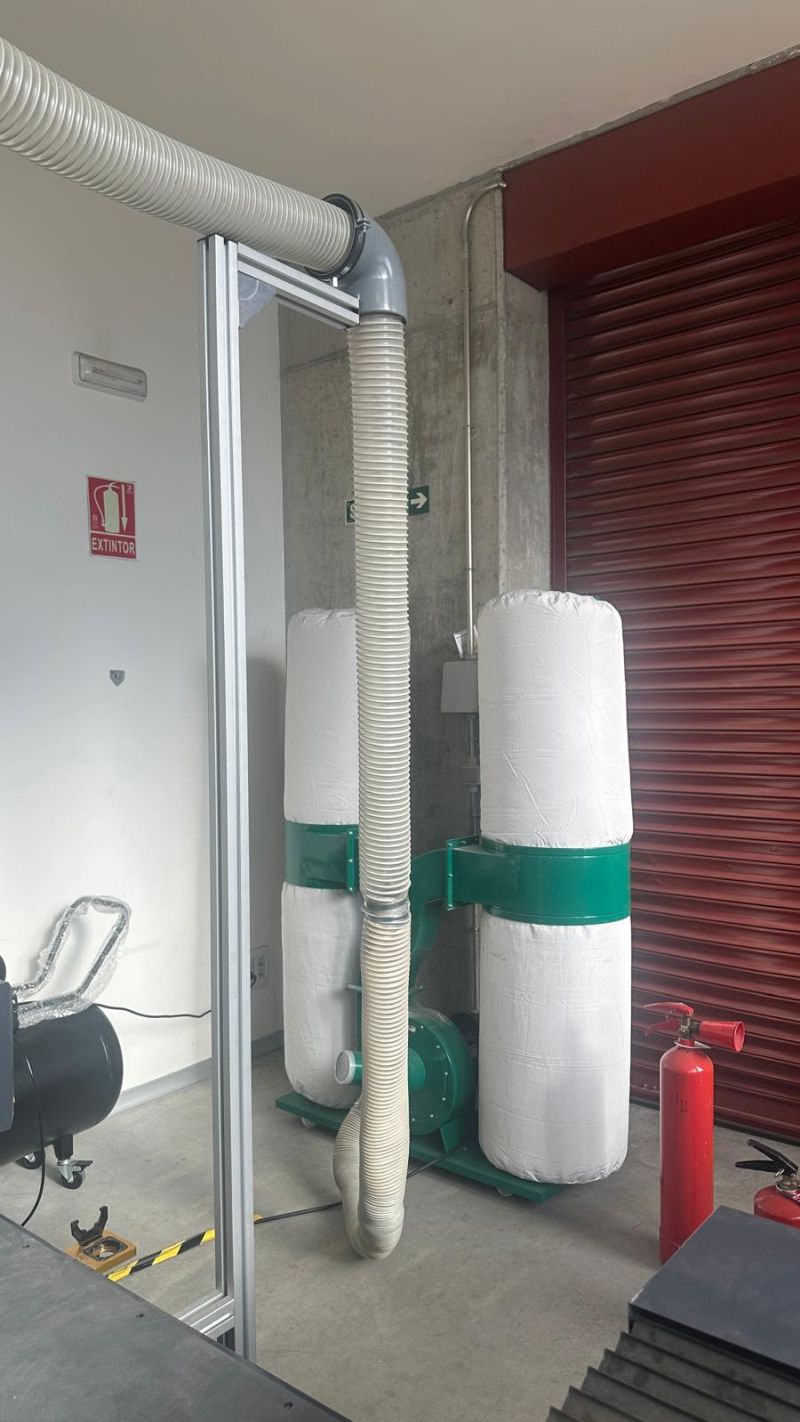
- Verify that the extractors and compressor are working correctly.
After finishing
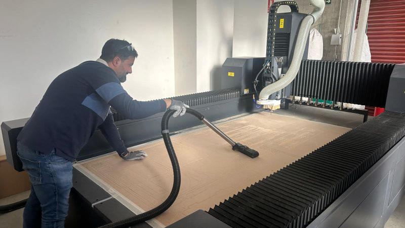
- Clean the machine bed and remove all cutting debris.
- Empty the condensate tanks.
- Check the chip collection bags to ensure they are not full and, very importantly, verify that no hot chips caused by friction have reached the bags, as this could create a serious fire hazard.
Regarding the working method, it is quite simple. Here I will focus on working with the CNC machine, assuming that the toolpath file is already prepared. The previous steps for generating this file are described in the individual assignment.
Workflow
- Once the safety checks have been completed with the machine stopped, we turn on the main switch, verifying that the compressor and fans start correctly.
- Turn on the computer and open the control software. Once the program has started, load the toolpath file.
- Place the material to be milled on the machine bed, making sure it remains within the working area.
- Activate the vacuum bed so the material does not move. If necessary, use clamps to secure it further.
- Set the zero position by manually placing the milling bit at the chosen origin point on the work surface.
- X and Y are positioned at the selected origin point.
- For Z, we carefully lower the bit until it just touches the material surface.
- Once the coordinates are saved, the tool can be lifted slightly to prevent starting too close to the material.
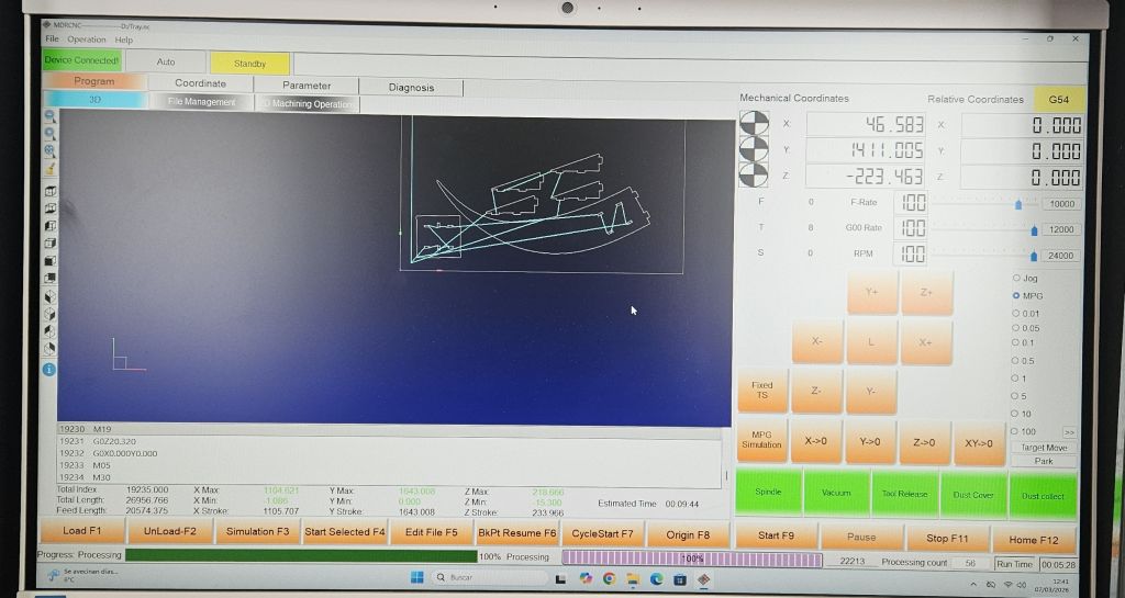
- Run a simulation on the computer to verify that all movements are correct. If everything looks correct, start the job while keeping a safe distance from the moving parts and especially from the cutting bit.
- Monitor the entire process and stop the machine immediately if any abnormal behavior occurs.
- Once the job finishes and the bit stops spinning, move the tool away from the material manually.
- Turn off the vacuum bed and remove any clamps used.
- Collect the finished pieces and clean the machine bed.
- If the machine will not be used again, turn off the main switch and the computer, and perform the shutdown checks mentioned earlier.
THE MATERIAL MUST BE FIRMLY FIXED AND MUST NOT MOVE.
Using the control interface or manual controller, we can move the spindle in the X, Y, and Z axes.
Group Assignment Reflection: CNC Machine Testing & Characterization
While my primary focus during our group assignment was establishing safety protocols, workspace configuration, and operational workflows for the large-format Bárcenas SW1325V-ATC CNC router, I actively participated in the machine's technical characterization tests alongside my teammate. Below is my technical reflection on the parameters tested and what I learned from them.
| Test Parameter | Methodology & Application | Key Results & Takeaways |
|---|---|---|
| Runout, Alignment & Joints | Testing axial alignment and mechanical tolerances by milling interlocking press-fit test joints. | Understanding alignment was vital for achieving clean geometric squareness. It defined the exact offset tolerances needed to ensure our final plywood assemblies fit together perfectly without binding. |
| Fixturing & Bed Stability | Evaluating sheet immobilization using mechanised clamps and screws driven directly into the MDF sacrificial bed. | Secure fixturing is a massive factor for safety. It keeps the stock perfectly flat, preventing vibrations or part-lifting that could ruin edges or fracture the tooling during heavy material removal. |
| Speeds, Feeds & Tooling | Benchmarking cut speeds, stepdowns, and feeds using 6mm and 2mm compression flat-end mills on 15mm plywood stock. | Optimizing the chip load allowed the machine to cut cleanly without burning the wood edges or straining the spindle, producing clean top and bottom finishes thanks to the compression bit flute geometry. |
What I Learned From This Machine Assessment:
- The Importance of Chip Load: Finding the precise balance between spindle speed (RPM) and feed rate is not just about cutting speed; it directly prevents overheating and vastly extends tool life on dense materials like 15mm plywood.
- Toolpath Strategy vs. Safety: As someone deeply focused on the machine workflow, participating in these tests showed me how a correct tooling path (such as utilizing onion skinning or bridges for smaller components) ensures parts do not break loose dangerously during a cut.
- Translating Tests to Projects: Grasping the real-world tolerances of the Bárcenas SW1325V-ATC gave me the exact data needed to confidently design structural parts later on, knowing precisely how the machine behaves under mechanical stress.
INDIVIDUAL ASSIGNMENT
Design
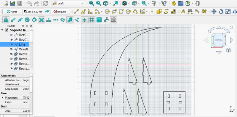
For this assignment I chose to work in the Draft Workbench in FreeCAD, since my design was 2D, and I did not create it parametrically. This allowed me to experiment with how this workbench operates.
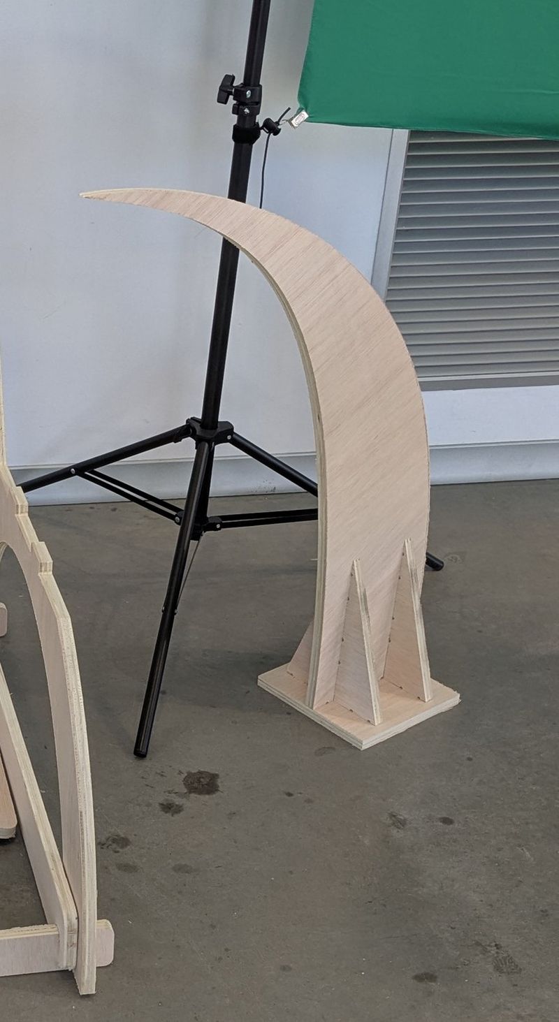
Since I had already designed a lamp during the laser cutting assignment, this time I decided to create the base for that lamp. It is a simple model that allowed me to experiment and discover that, although Draft seems easier because it is based on direct vector drawing, it also has some nuances.
Recommendations
- Always activate Snap so that when drawing, lines automatically connect to each other.
- Another important thing I learned is that in order to trim or modify certain shapes, they must first be downgraded to simpler geometry. For example, if we want to trim a rectangle intersecting another rectangle, both shapes must be converted into individual lines that can then be trimmed.
- To draw parallel lines, we can use the Offset tool, which allows quick and constrained copies of an existing line.

Otherwise, FreeCAD treats the rectangle as a complete object that cannot be partially modified.

Little by little, I keep learning.
Once the design was completed, I exported it as a DXF file. Here I encountered another issue that I had not experienced before: FreeCAD did not export the design correctly because of a Bezier curve I had drawn. The solution was to update the DXF export libraries.
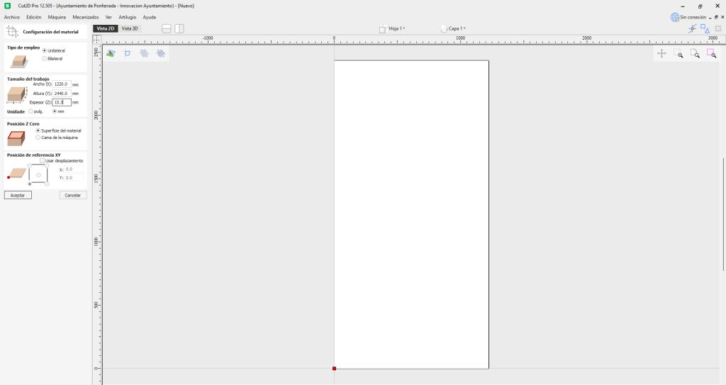
Once the DXF file was generated, the next step was to move to the toolpath preparation software, which generates the G-code that the CNC machine understands. In the FabLab we use CUT2D.
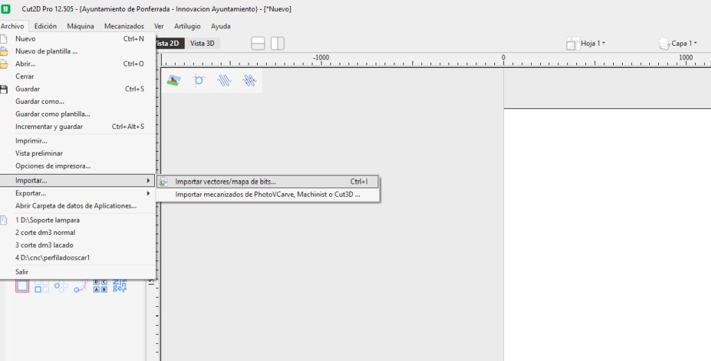
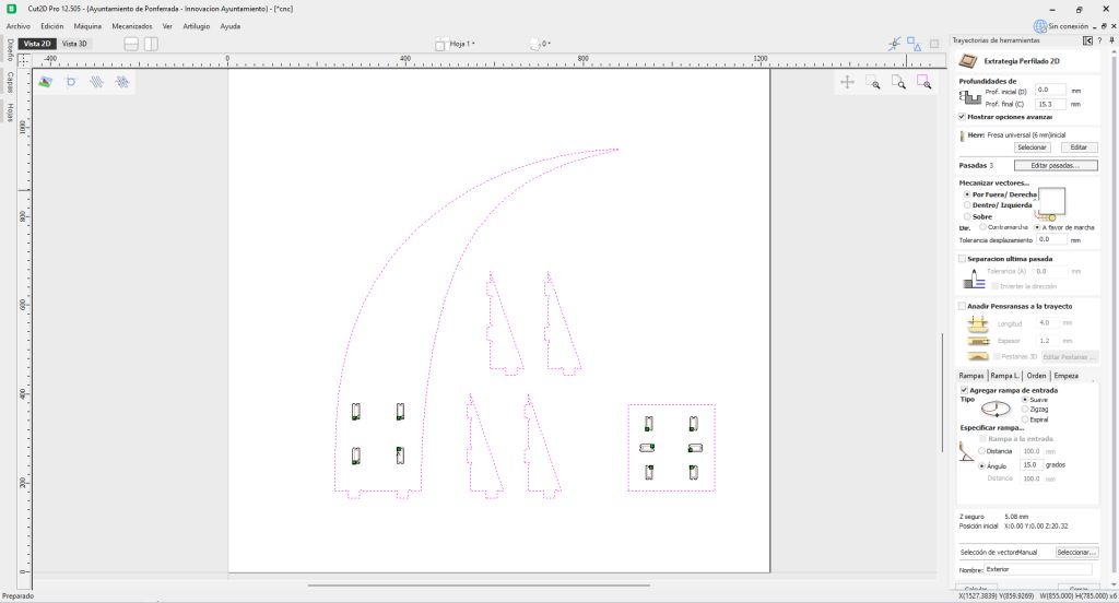
Steps in CUT2D
- Create a new project and define the size of the material. In this case we used a board of 1220 mm × 2440 mm with a thickness of 15 mm.
- Import the vector design (DXF).
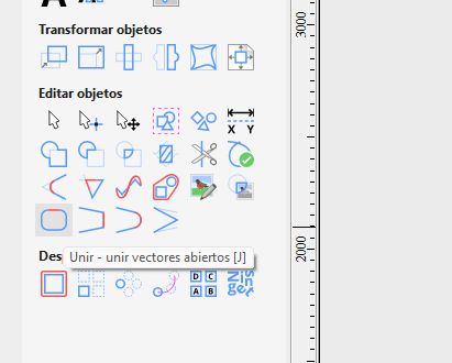
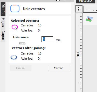
- Verify and close all vectors if necessary. The software provides tools to automatically join vectors that may have become separated during export/import. Open vectors can cause machining problems, so they must be fixed.
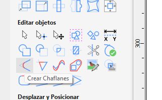
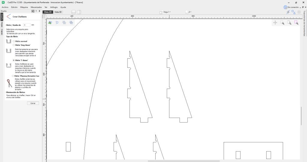
- At this point we introduce the concept of dogbones, explained later. The software allows them to be added semi-automatically without modifying the original design.
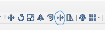
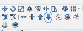
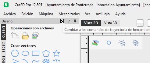
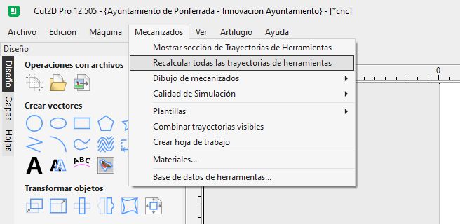
- Switch to the toolpath commands screen by clicking the small arrow in the upper-left corner (which honestly took me a while to find).
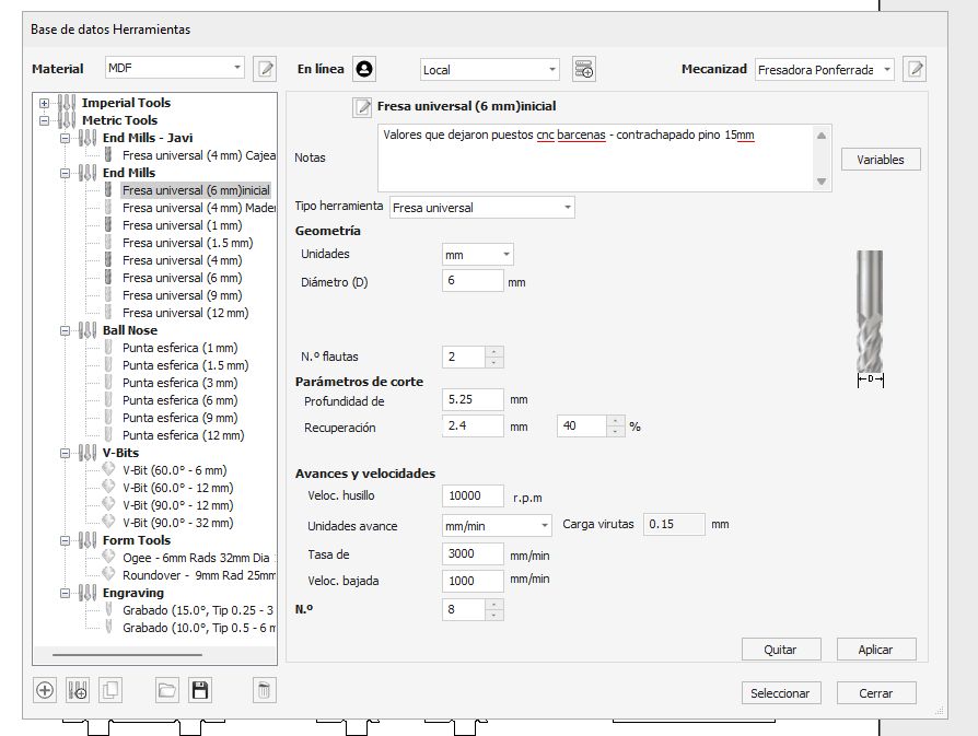
- Following the instructions on the screen, we configure:
- Cutting depth 5.25mm
- Tool type. Diameter 6mm
- Number of passes
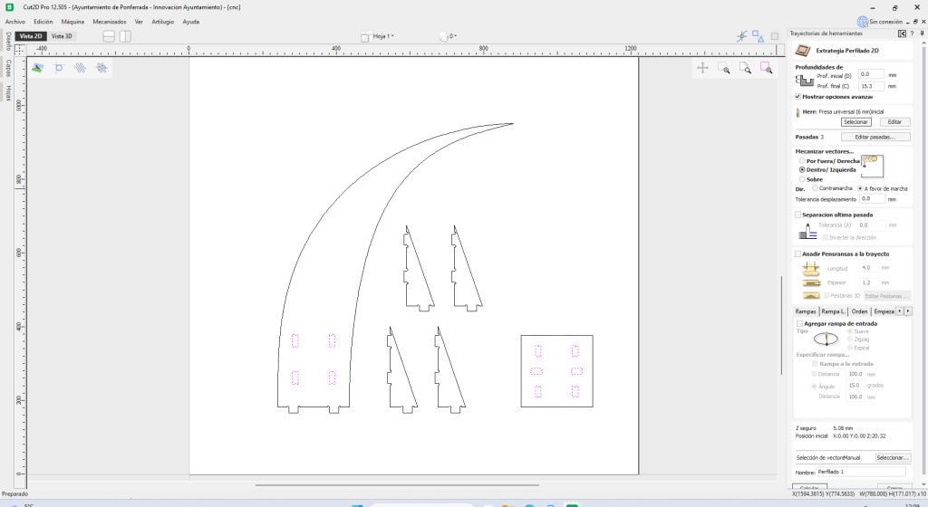
- Vectors to cut on the inside first
- Cutting direction
- Optional finishing pass
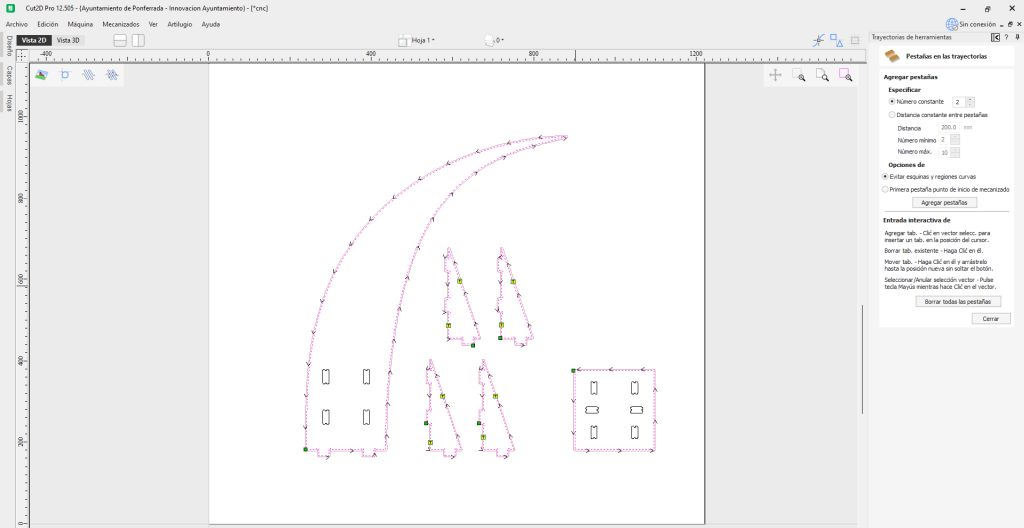
- Tabs (to keep small parts attached)
- Entry ramp, which must always be added because end mills cut laterally, not vertically like a drill bit.
- Calculate and generate the internal toolpaths, then repeat the process for the external ones.
- Select the type of machining operation (pocket, profile cut, engraving, etc.).
- Finally, simulate the toolpath and export the G-code file for the CNC machine.
On the recommendation of the Fab manager, we set it to 15.3 mm to ensure the cut goes completely through the material. Under the board there is a sacrificial plywood layer, so if the bit reaches it, it will not damage the machine bed.
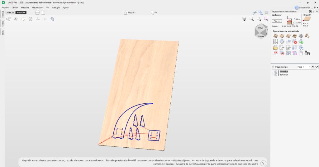
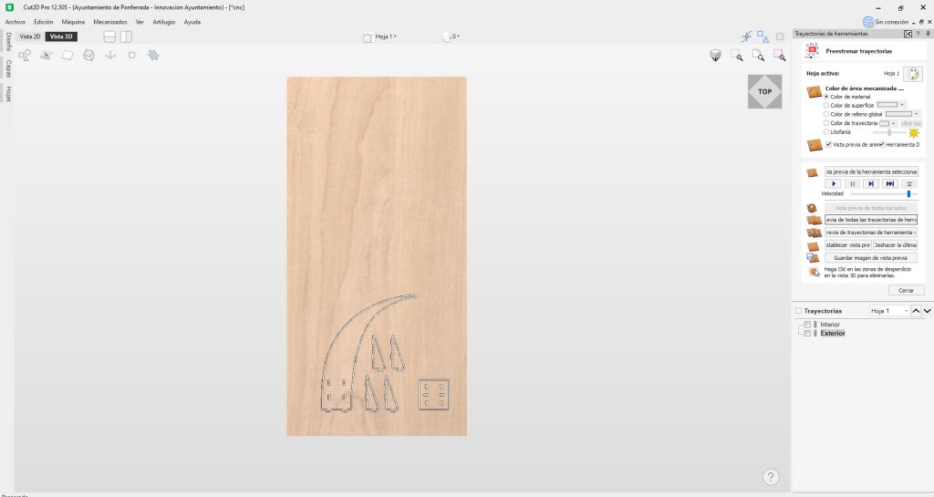
If during the simulation something looks wrong, for example the position of parts, we can return to the design screen, move the parts, and automatically recalculate the toolpaths without repeating the entire process.
From this point on, we only need to go to the CNC machine and follow the procedure described in the group assignment.
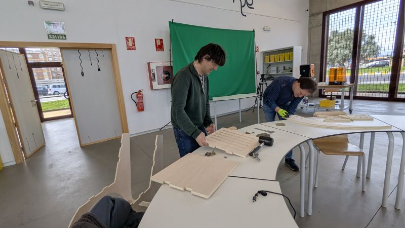
And finally… assemble the design!
Dogbones
Dogbones are necessary due to a physical limitation of milling machines: the milling bits are round.
This means that when a straight cut ends, the tool leaves a rounded internal corner with a radius equal to the tool diameter. If this occurs on an external corner, it is not a problem because the shape remains correct. However, for internal corners, this small radius prevents two parts from fitting perfectly together.
To solve this, the tool must extend slightly beyond the corner, removing a small amount of extra material. This creates a small circular relief known as a dogbone, allowing square components to fit properly.
Of course, this also removes a small amount of material that was not originally part of the design, so the goal is to place these reliefs in locations where they will be less visible once the assembly is complete.
This concept is very well explained in the following article:
DogbonesCONCLUSION
This assignment has been very meaningful for me; it reminded me of old times, and I enjoyed seeing how these types of machines are used today. I’m left wanting more, and when I have more time, I’m sure I will make further use of this knowledge.