Week5 3D Scanning and Printing.
The assignment for this week focuses on 3D printing. It is divided into a group task and an individual task. We must document how the 3D printers available in the FabLab work and test their performance. After that, we must design and print an object that cannot be manufactured using subtractive techniques. Finally, we must use and document the operation of the 3D scanner that is also available in the FabLab.
- Group Assignment
- INDIVIDUAL ASSIGNMENT
- FILES DOWNLOAD
GROUP ASSIGNMENT
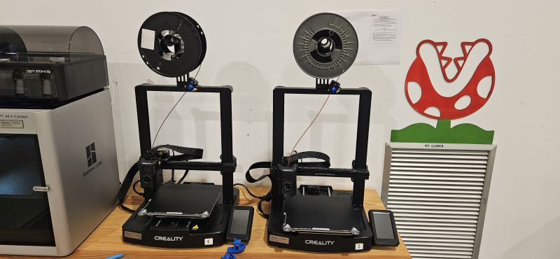
FabLab Leon work groupCreality Ender-3 V3 KE Printer
After dividing the tasks, in my case I will document the Creality Ender-3 V3 KE printer.
As an open-frame printer, it may seem simple at first glance, but it offers several very significant advantages. Below, I detail its main technical characteristics.
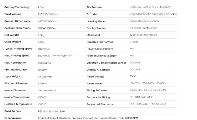
Main specifications:
Main advantages:
Main disadvantages:
Once the different characteristics of the printer have been evaluated, I proceed to test its capabilities in situ. For this purpose, I print several predefined models provided by the FabLab, which allow me to observe the printer’s tolerance margins and limitations.
Test results:
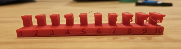
Overhang
This test shows the machine’s limit when printing horizontally with a gap underneath the part. Beyond this limit, supports are required to prevent the part from collapsing during printing. Once printed, we can see that problems start to appear from 5 mm onward on the underside of the part.
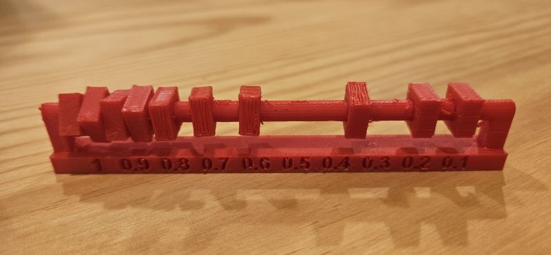
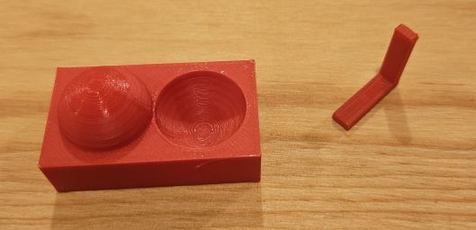
Clearance
This test is used to determine the minimum spacing between two parts that still allows them to move independently. After printing, it is clear that the last two elements are fixed to the axis and cannot be moved, while the third-to-last element moves with difficulty. This matches the printer’s 0.1 mm accuracy, since having two parts results in a combined tolerance of 2 × 0.1 mm = 0.2 mm, exactly as indicated by the test.
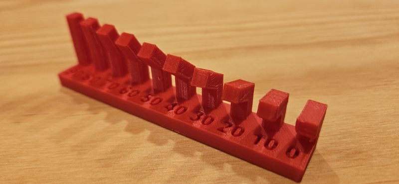
Angle
The purpose of this test is to determine up to which angle the printer can print without using supports and without deforming the part. In this case, the printer performs very well, with failures only appearing in the last two cases, at 0 and 10 degrees.
Bridging
This test evaluates the maximum horizontal distance that can be printed without the upper part collapsing. Beyond this point, supports would be required. No issues were detected, and the printer successfully printed the longest distance in the test.
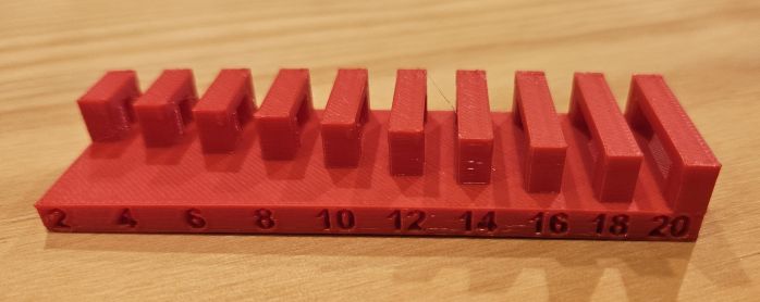
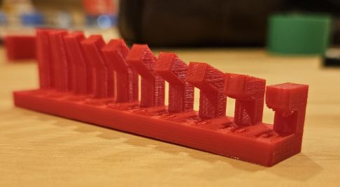
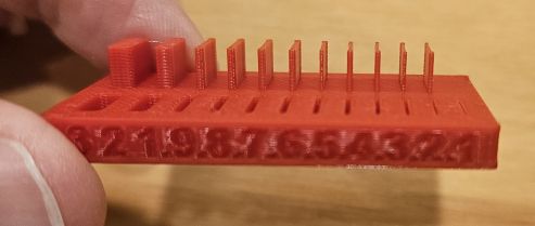
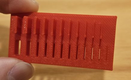
Thickness
This test determines the printing error margin by printing increasingly thinner slots until they fuse together. This fusion point indicates the minimum printable feature size. In this case, only the last slot of 0.1 mm presented problems.
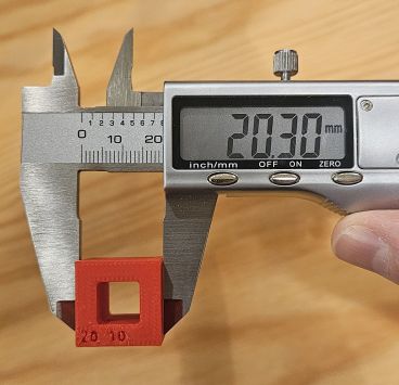
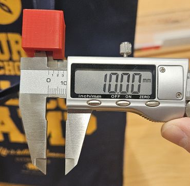
Dimension
Related to the previous test, this one compares the designed dimensions with the actual printed dimensions. The internal dimensions are almost perfect, while the external dimensions are slightly larger than expected. Depending on the measurement area, the readings are not always consistent, showing a somewhat irregular surface with a precision of around 0.2 mm.
Anisotropy
This test evaluates the preservation of the physical properties of an object, such as elongation and rigidity. Visually, no imperfections were detected.
Surface finish
This test allows us to observe the surface quality of the printed object. Slight, very fine irregularities can be seen, which could be resolved with light post-processing or polishing.
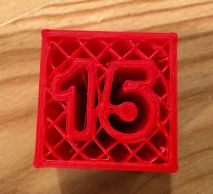
Infill
This test shows the different infill patterns that can be achieved with the printer. In this case, we can clearly observe the infill pattern configured directly in the software.
Once the characteristics and limitations of the printer are understood, the workflow is straightforward.
A 3D model is created using any 3D design software and then exported in STL format, which is supported by all slicing software used to operate 3D printers.
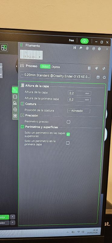
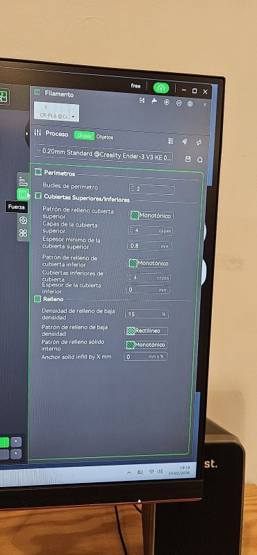
In our case, the software used is Creality Print. After importing the model, the final printing parameters can be adjusted:
Default value set to 0.2 mm
Default value of 2
Filament temperature set to 220 °C, following the manufacturer’s recommendation, and bed temperature set to 55 °C, since at 50 °C the part detached from the bed on one occasion
A monotonic pattern was used
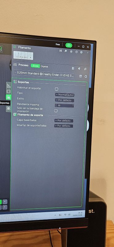
Supports were only required for the Clearance test piece
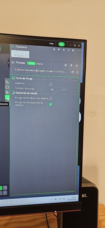
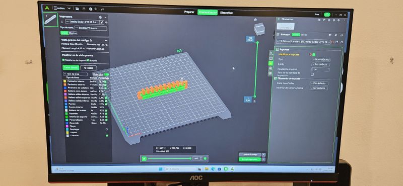
The software allows many more configurations and options, but these are the most relevant ones. Once these settings are defined, the model is sliced. The software divides the 3D model into stacked 2D horizontal layers, generating a G-code file, which is the format recognized by the printer to print the object layer by layer according to the slicing configuration.
INDIVIDUAL ASSIGNMENT
The individual assignment consists of designing and printing a model that cannot be manufactured using subtractive methods, making it necessary to use additive manufacturing techniques such as 3D printing.
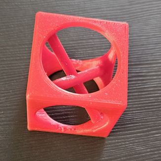
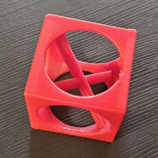
For this purpose, I designed a cube in FreeCAD with smooth exterior walls, but with a hollow spherical interior. Additionally, I incorporated two ribs crossing the interior of the cube. Finally, the holes in the exterior walls were rounded.
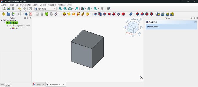
DESIGN
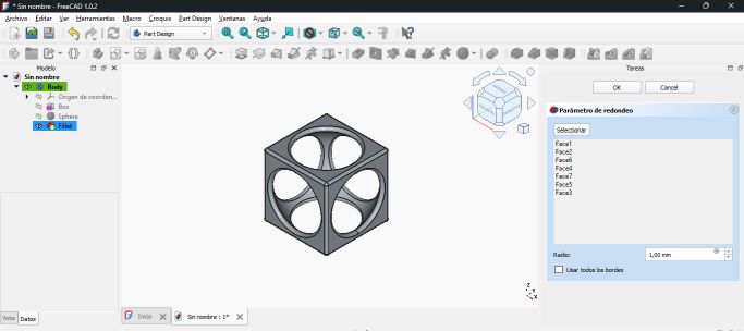
The first step was to create a 3D cube using the Additive Cube tool in the Part Design workbench.
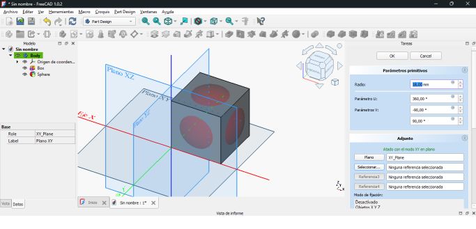
Next, using the Subtractive Sphere tool, I removed the interior of the cube. The sphere was positioned so that its center coincided with the center of the cube, and it was given a diameter slightly larger than the side length of the cube. This allowed the cube’s side faces to be perforated, making the interior visible.
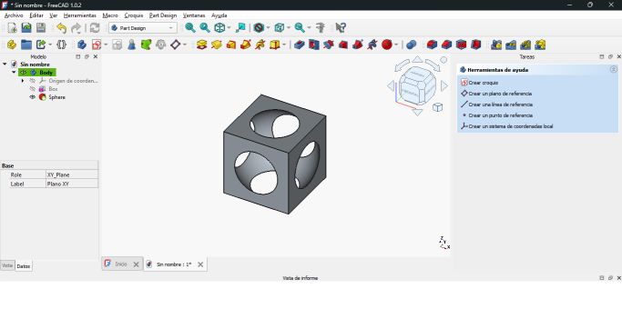
Using the Fillet tool, I rounded all the exterior faces as well as the interior edges of the cube.
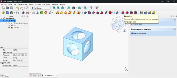
From this point, I created two new bodies using the Additive Cylinder tool. These cylinders were positioned and inclined so that they crossed the interior of the cube through its vertices, intersecting at the center of the cube.
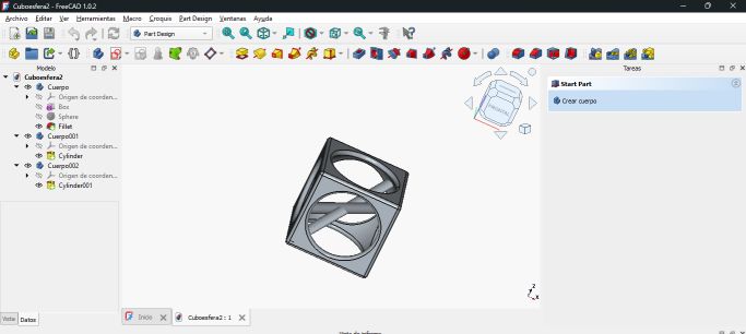
In this way, I created a shape that cannot be manufactured by other means. Although the cube could be milled and the holes could be machined, achieving a spherical interior finish and creating two internal ribs crossing the cube is almost impossible using methods other than 3D printing.
PRINTING
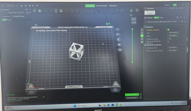
Once the design was completed, I exported it in STL format and went to the FabLab to print it.
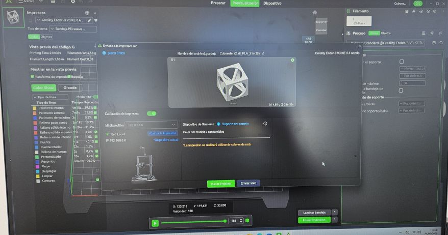
At the FabLab, I used Creality software to load the STL file and configure the print with the following parameters:
- Filament type: PLA 1.75 mm
- Layer height: 0.2 mm
- Extruder temperature: 220 °C
- Bed temperature: 50–55 °C
- Supports: NO
- Perimeters: 2 loops
- Infill: 15% density, monotonic pattern
After setting the print parameters and slicing the model, I decided to take the risk of printing without supports to observe the result.
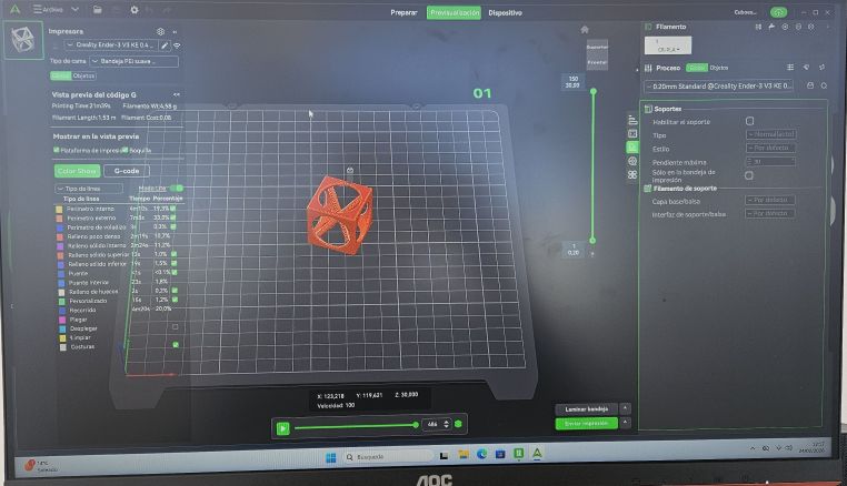
In the first print, the result was not satisfactory. Without supports, at around 80% of the print, the extruder collided with the upper part of the openings, causing the part to detach from the build plate and forcing me to abort the print.
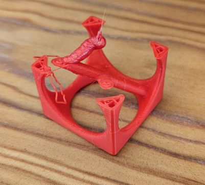
The solution was not to add supports, but to increase the bed temperature from 50 °C to 55 °C. With this adjustment, the second print was successful.
Finally, printing this part required 20 minutes and 1.53 meters of filament.
SCANNING
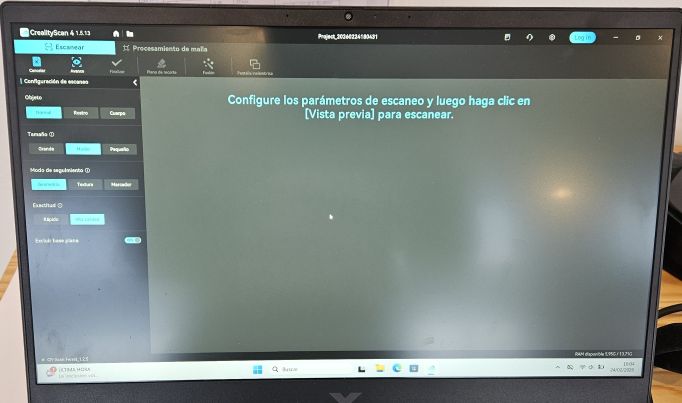
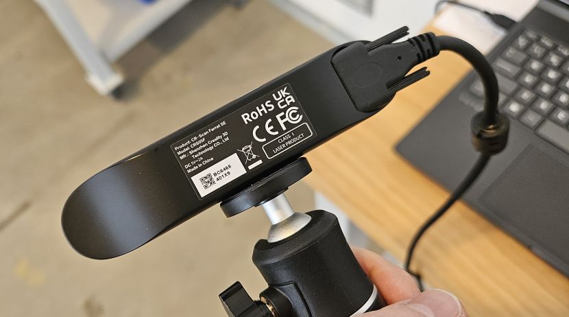
For the scanning task, I used the scanner available at the FabLab: a CR-SCAN FERRET SE (CRS05F) along with the Creality Scan application.
This handheld scanner allows easy 3D scanning of objects. The software is very intuitive, with simple initial parameters. The only “trick” is to move the scanner slowly while maintaining a constant distance from the object, following the on-screen instructions and allowing the point cloud to be generated gradually.
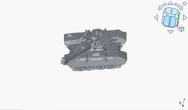
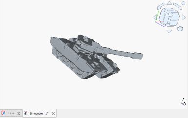
In my case, I scanned a 3D puzzle figure shaped like a tank, and the result was quite satisfactory.
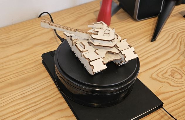
Once the scan was completed, I used the same application to delete the incorrectly generated parts and exported the result as an STL file. From that point on, the workflow to edit and print the model is the same as previously described.