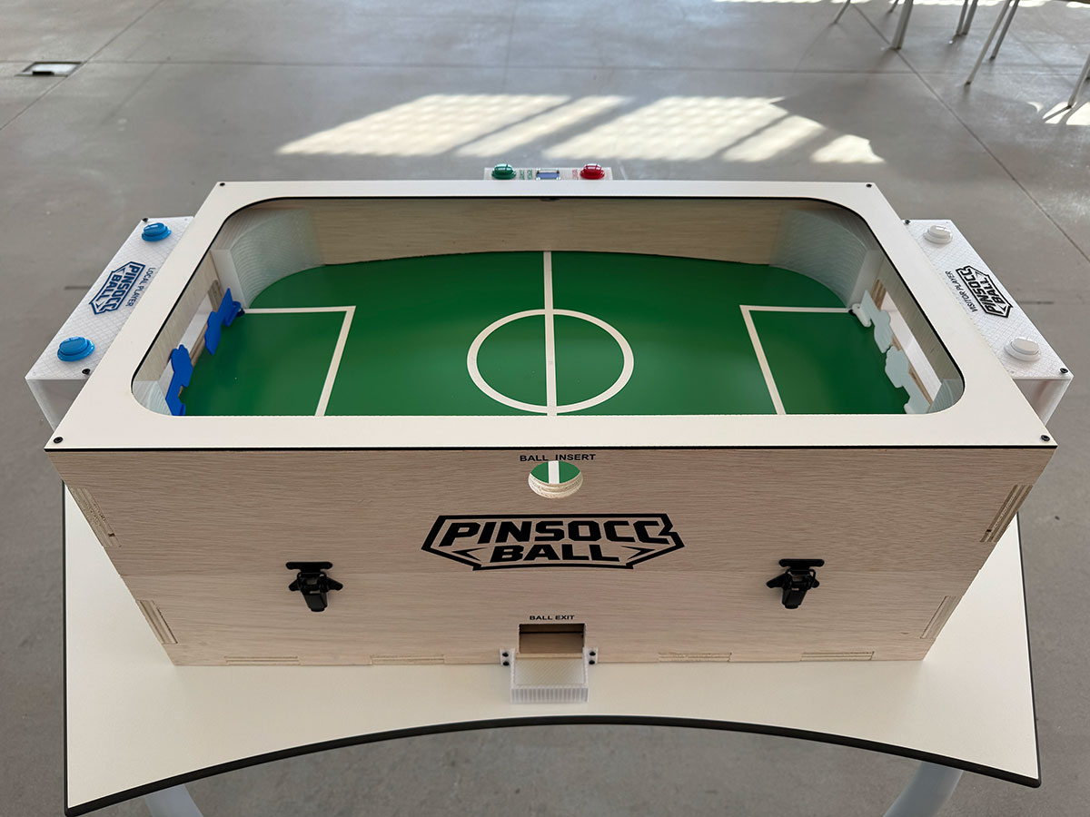
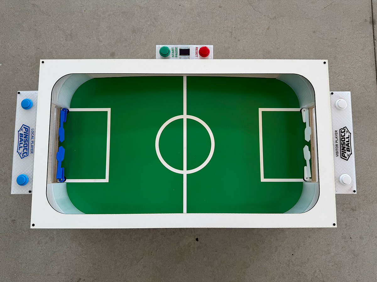
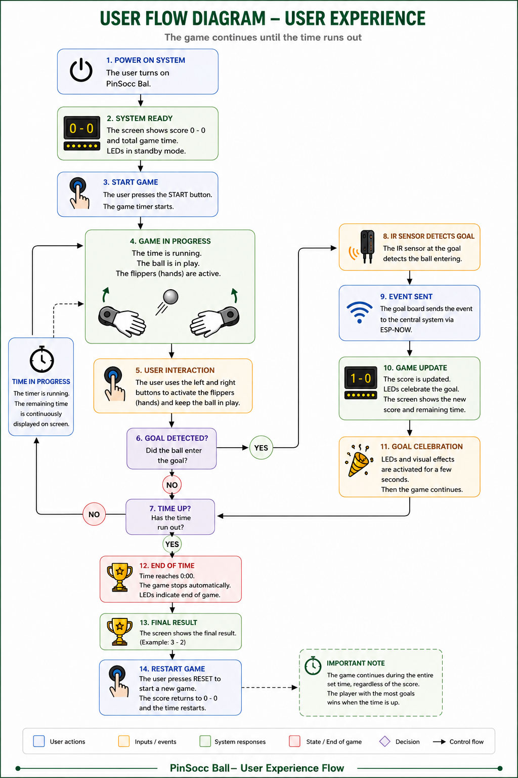
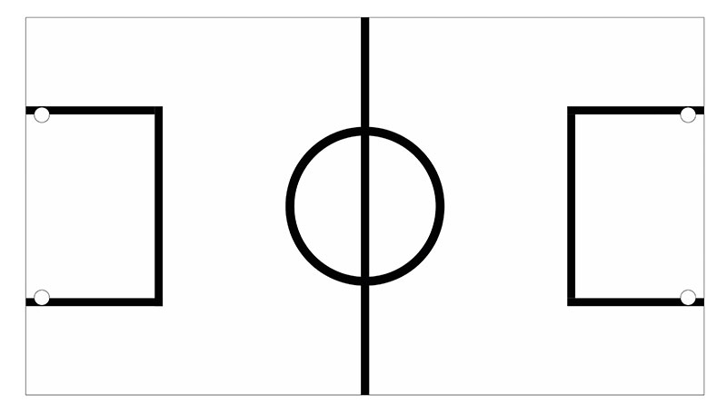
This project is a game that combines concepts from both a pinball and table football.
The gameplay consists of scoring goals in the opponent’s goal using two flippers similar to those found in a pinball machine.
Each player controls two flippers acting as if they were a football goalkeeper’s hands, trying to defend their own goal while also attempting to send the ball toward the rival side and score.
The goal is to create a simple, fun, and engaging experience based on reflexes, timing, and player interaction.
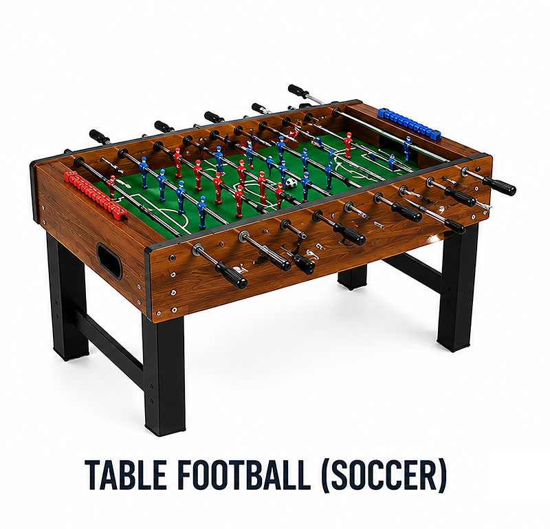
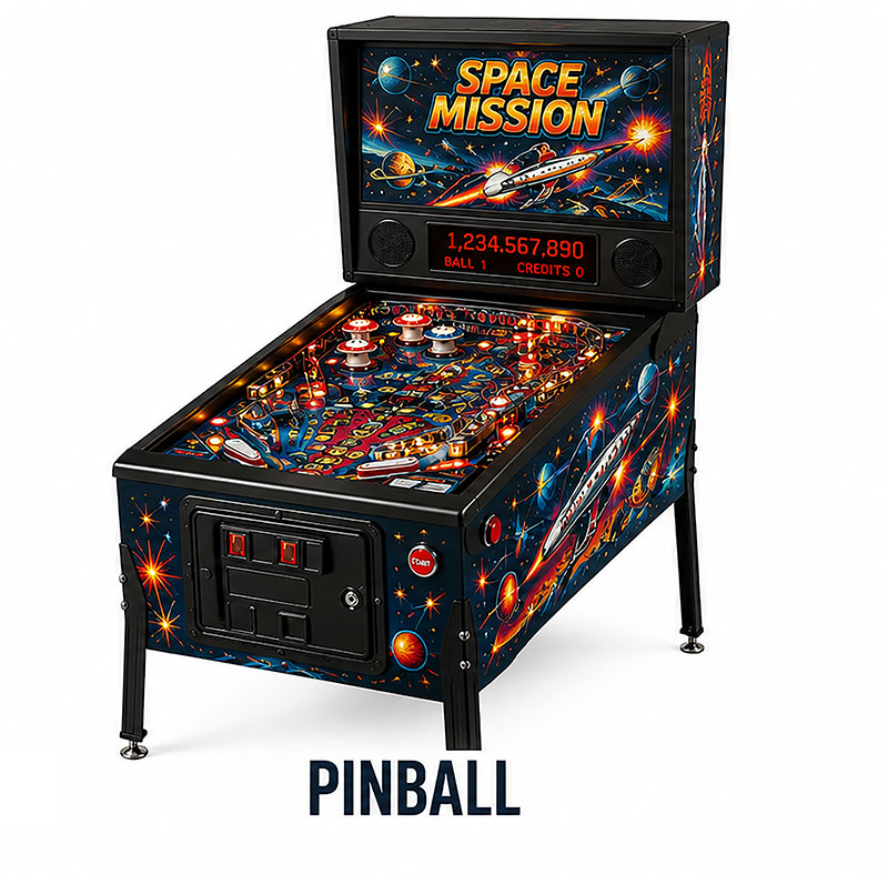
Table football (soccer)PinballPinSocc BallPinSocc Ball
Throughout the development process, I integrated 2D and 3D design, digital fabrication, electronics, programming, and mechanical assembly to build a fully functional system.
The result is an interactive machine that combines skill, reflexes, and competition, showing how the different disciplines learned during Fab Academy can come together in a single project.
You can go to to de Develoment page to see the evolution/tests or to de Proposal page to first understand the initial idea.
Slide
PINSOCC BALL Slide (size: 0 Kb -click to enlarge-).
'PinSocc Ball song' is a song created specifically in Suno for the final project presentation video. Here is the full version.
Presentation
On June 8th, 2026, I presented my final project, PinSocc Ball, during the first day of Fab Academy 2026 final presentations.
PinSocc Ball is a game that combines the mechanics of a pinball machine and a table football game, inspired by an arcade machine I played many years ago and never found again. This project integrates digital fabrication, electronics design and production, embedded programming, networking, and system integration into a fully functional interactive machine.
The following video shows the final project FA'26 presentation:
You can also watch all the presentations from the first day of Fab Academy 2026 final project presentations through the following Vimeo link.
It looks great. It looks fun and nicely finished.
But yeah, it's an interesting conception.
I've never seen pinball soccer. It's a nice idea.
And it looks nicely finished and integrated.
In fact, it'd be nice if the video had at the end some excited kids playing the game.
Neil Gershenfeld (Jun 8, 2026)
Q & A
This project is a game that combines concepts from both a pinball machine and a table football game.
The gameplay consists of scoring goals in the opponent’s goal using two flippers similar to those found in a pinball machine.
Each player controls two flippers acting as if they were a football goalkeeper’s hands, trying to defend their own goal while also attempting to send the ball toward the rival side and score.
The goal is to create a simple, fun, and engaging experience based on reflexes, timing, and player interaction.
The main inspiration for this project comes from an arcade game I played when I was younger and that I have never seen again since then. Although pinball machines and table football games still exist today, that machine combined elements of both concepts in a different way and left a strong impression on me.
After deciding to develop this idea, I researched similar projects and found several examples of two-player pinball machines. However, I could not find any project combining a football field with two opposite goals and gameplay focused on defending and attacking using flippers.
Besides that initial inspiration, I also used references from existing pinball systems, football games, and different mechanical and electronic solutions discovered during the development process.
I will design all the main mechanical and electronic elements required for the project. This includes:
Outer structure and chassis
Playing field
Goal detection system with IR sensors
Game control logic
Automatic ball return system with ramps
Score display
Lighting effects with LEDs
I will also design the necessary PCBs, holders, and custom 3D printed parts required to integrate all the systems together.
Several parts and systems will be designed and manufactured specifically for this project:
Wooden outer case structure
MDF top cover and ball return system (ramps)
Laser engraved and cut playing field
3D printed parts such as hand flippers and PCB holders/cases
Custom electronic system and PCBs
LED lighting system and score display
Game control system and logic
Different fabrication processes learned during Fab Academy will be used throughout the project:
CNC milling for manufacturing the wooden structure
2D design and laser cutting/engraving for the playing field
Laser cutting on MDF for the top cover and ramps for the ball return system
3D design and printing for custom components
PCB design and CNC fabrication
Embedded programming
Mechanical and electronic system integration
The combination of all these techniques will allow me to fabricate most of the project instead of relying on external parts.
The project will be evaluated by testing both its technical functionality and the overall user experience.
Some evaluation criteria will include:
Correct operation and responsiveness of the flippers
Accurate goal detection
Reliable operation of the automatic ball return system
Proper score display and lighting effects
Successful integration of all mechanical and electronic systems
Quality of assembly and final appearance
Whether the game feels dynamic, balanced, and enjoyable for different users
Additionally, real user testing will be performed to identify possible improvements and detect any issues or areas that could be optimized.
This project shows how digital fabrication, electronics, embedded programming, networking, and system integration can come together to create a complete and playable product.
Beyond the current prototype, PinSocc Ball has several possible future evolutions, such as a mobile and web platform to store match statistics, manage players, and organize championships.
Other improvements could include an automatic ball elevator system, online rankings, additional game modes, and sound or haptic feedback to make the experience more immersive.
These developments could turn the project from a standalone arcade game into a more connected, scalable, and engaging gaming platform.
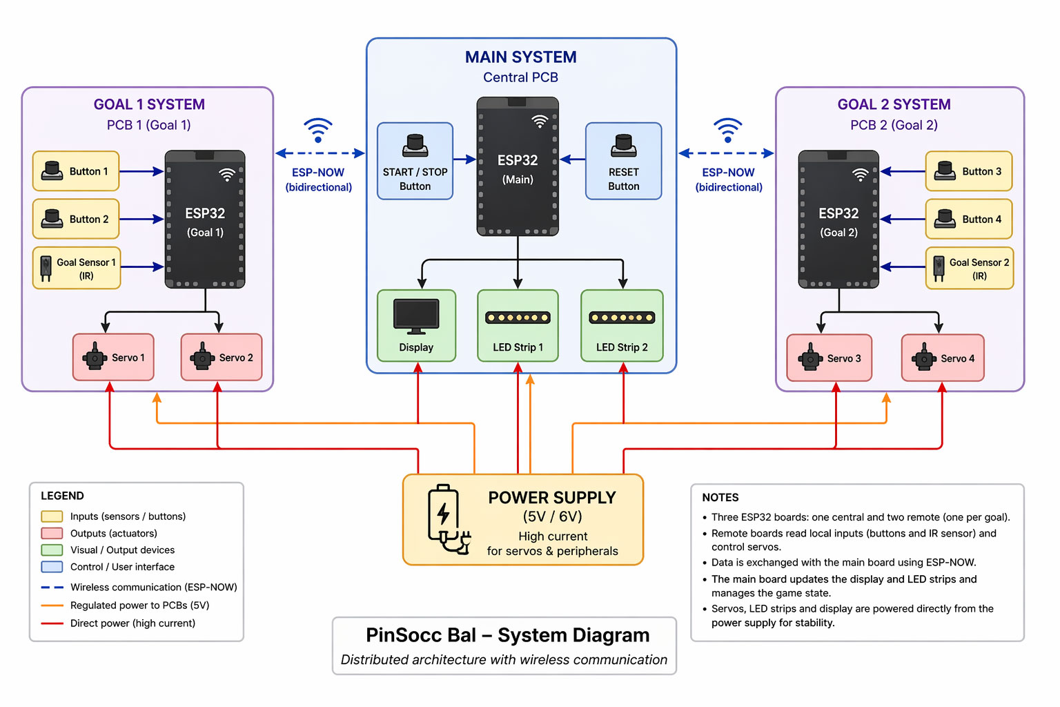
Write a complete Arduino program for a PinSocc Ball scoreboard using ESP32, with WiFi.h, WebServer.h, esp_now.h, Wire.h, Adafruit_SSD1306.h, and Adafruit_NeoPixel.h. The system must include a 128x64 SSD1306 OLED over I2C on D4/D5, a 106-LED NeoPixel strip on GPIO18 divided into zones for bands, local goal, and visitor goal, two physical buttons on D0 and D1 for start/stop and reset, a web server running in Access Point mode with SSID "PinSoccBall" and password "12345678", and goal reception through ESP-NOW. The match must last 180 seconds, display score, time, and status on the OLED and web page, allow local/visitor goals from the web or ESP-NOW, show a GOAL message for 1.5 s, handle start/stop, allow reset only when the game is stopped by holding the reset button for 2 s, and automatically reset after the end animation. The LED strip must show green bands during the game, a green blinking start effect, a red warning during the last 10 s, a goal effect where the scoring goal zone turns green and the opposite zone turns red, and a final winner/tie animation. Use millis() for the timer and non-blocking effects, separate functions for display, LEDs, game logic, ESP-NOW, and web server, and include Serial debug messages.
Español
Escribe un código completo para Arduino para un marcador PinSocc Ball con ESP32, usando WiFi.h, WebServer.h, esp_now.h, Wire.h, Adafruit_SSD1306.h y Adafruit_NeoPixel.h. El sistema debe tener una pantalla OLED SSD1306 128x64 por I2C en D4/D5, una tira NeoPixel de 106 LEDs en GPIO18 dividida en zonas para bandas, portería local y portería visitante, dos botones físicos en D0 y D1 para start/stop y reset, un servidor web en modo Access Point con SSID "PinSoccBall" y contraseña "12345678", y recepción de goles por ESP-NOW. El partido debe durar 180 segundos, mostrar marcador, tiempo y estado en OLED y web, permitir goles locales/visitantes desde la web o por ESP-NOW, mostrar mensaje GOAL durante 1,5 s, controlar start/stop, permitir reset solo con el juego parado manteniendo el botón 2 s, y reiniciar automáticamente tras el final. La tira LED debe mostrar bandas verdes durante el juego, parpadeo verde al inicio, aviso rojo en los últimos 10 s, efecto de gol con la portería que marca en verde y la otra en rojo, y animación final según ganador o empate. Usa millis() para temporizador y efectos no bloqueantes, funciones separadas para display, LEDs, juego, ESP-NOW y servidor web, y mensajes por Serial para depuración.
Code · PinSoccB_LOCAL.inoShow code
English
Write a complete Arduino program for a XIAO ESP32-C6 using WiFi.h, esp_now.h, and ESP32Servo.h. This PCB is installed in the local goal, so when the IR sensor detects the ball, it must send a visitor goal event via ESP-NOW to a main board whose MAC address is defined in the code. The system must include an IR sensor on D1 using INPUT_PULLUP, two buttons on D8 and D10 to control two flippers, and two servos: right servo on GPIO17 / D7 and left servo on D2. The right servo must move from 140° to 60° and return, while the left servo moves from 60° to 140° and returns, holding the hit position for 150 ms using non-blocking millis() logic. Goal detection must happen when the IR sensor goes LOW, with a 300 ms debounce, sending an ESP-NOW structure containing boardID and eventType. Include ESP-NOW setup in WIFI_STA mode, send callback registration, peer registration, Serial debug messages, and falling edge detection for the button presses.
Español
Escribe un código completo para Arduino para un XIAO ESP32-C6 usando WiFi.h, esp_now.h y ESP32Servo.h. Esta PCB está instalada en la portería local, por lo que si el sensor IR detecta la pelota, debe enviar por ESP-NOW un evento de gol visitante a una placa principal cuya MAC está definida en el código. El sistema debe incluir un sensor IR en D1 con INPUT_PULLUP, dos botones en D8 y D10 para controlar dos flippers, y dos servos: servo derecho en GPIO17 / D7 y servo izquierdo en D2. El servo derecho debe moverse de 140° a 60° y volver, y el izquierdo de 60° a 140° y volver, manteniendo la posición de golpe durante 150 ms con lógica no bloqueante usando millis(). La detección de gol debe hacerse cuando el sensor IR pasa a LOW, con un debounce de 300 ms, enviando una estructura ESP-NOW con boardID y eventType. Incluye configuración de ESP-NOW en modo WIFI_STA, registro de callback de envío, alta del peer, mensajes por Serial para depuración y detección de pulsaciones por flanco de bajada.
Code · PinSoccB_VISITORShow code
English
Write a complete Arduino program for a XIAO ESP32-C6 using WiFi.h, esp_now.h, and ESP32Servo.h. This PCB is installed in the visitor goal, so when the IR sensor detects the ball, it must send a local goal event via ESP-NOW to a main board whose MAC address is defined in the code. The system must include an IR sensor on D1 using INPUT_PULLUP, two buttons on D8 and D10 to control two flippers, and two servos: right servo on GPIO17 / D7 and left servo on D2. The right servo must move from 130° to 70° and return, while the left servo moves from 70° to 130° and returns, holding the hit position for 180 ms using non-blocking millis() logic. Goal detection must happen when the IR sensor goes LOW, with a 300 ms debounce, sending an ESP-NOW structure containing boardID and eventType. Include ESP-NOW setup in WIFI_STA mode, send callback registration, peer registration, Serial debug messages, and falling edge detection for the button presses.
Español
Escribe un código completo para Arduino para un XIAO ESP32-C6 usando WiFi.h, esp_now.h y ESP32Servo.h. Esta PCB está instalada en la portería visitante, por lo que si el sensor IR detecta la pelota, debe enviar por ESP-NOW un evento de gol local a una placa principal cuya MAC está definida en el código. El sistema debe incluir un sensor IR en D1 con INPUT_PULLUP, dos botones en D8 y D10 para controlar dos flippers, y dos servos: servo derecho en GPIO17 / D7 y servo izquierdo en D2. El servo derecho debe moverse de 130° a 70° y volver, y el izquierdo de 70° a 130° y volver, manteniendo la posición de golpe durante 180 ms con lógica no bloqueante usando millis(). La detección de gol debe hacerse cuando el sensor IR pasa a LOW, con un debounce de 300 ms, enviando una estructura ESP-NOW con boardID y eventType. Incluye configuración de ESP-NOW en modo WIFI_STA, registro de callback de envío, alta del peer, mensajes por Serial para depuración y detección de pulsaciones por flanco de bajada.
Final assembly and installation
Down wood case
Down wood case
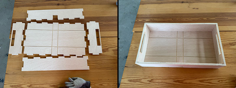
Once all the parts had been milled, I lightly sanded them to improve the finish and remove any small imperfections. With the pieces ready, it was time to assemble the lower cabinet.
Since the entire structure was designed as a press-fit system, all the parts could be joined together without the need for screws, glue, or any other fastening elements. Using a rubber mallet, I carefully fitted each piece into place, making sure that every joint was fully seated and aligned.
The use of dogbones in the internal corners also ensured that the parts fit together correctly despite the diameter limitations of the milling tool used during fabrication.
Once the assembly was completed, the result was a strong and rigid structure that would serve as the foundation for all the mechanical and electronic components of the project.
Upper wood case
Upper wood case
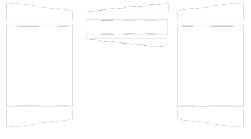
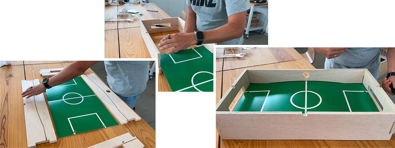
The next assembly stage was building the upper cabinet, which forms the visible structure of the playing field. Just like the lower cabinet, all parts were designed using a press-fit system, eliminating the need for screws or adhesives.
This section consists of the four milled perimeter panels. Each panel includes an internal slot designed to hold the playing surface, which had previously been laser-cut and engraved from a bi-layer board.
To make the assembly process easier, I first joined the two long side panels and one of the short side panels. With the structure partially open, I was able to slide the playing surface into position through the slots until it was fully seated.
Once the playing surface was correctly aligned, I completed the assembly by installing the final side panel, closing the structure and securely holding the playing field in place.
Upper wood case assembly (video size: 0 Mb).
High quality video and 1x speed available on my YouTube channel ↗️.
Ramps Assembly
Ramps Assembly
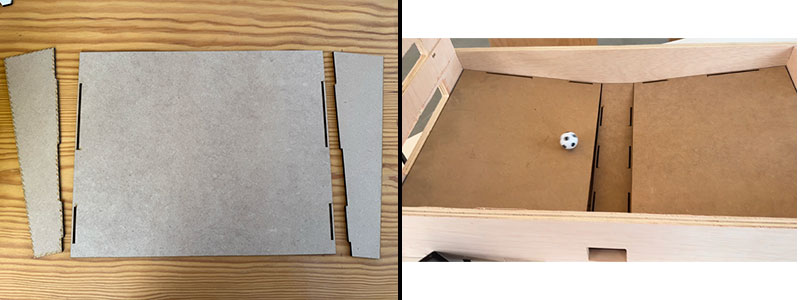
The next step was assembling the ramps responsible for guiding the ball back into the playing area. These parts were laser-cut from 3 mm MDF and designed following the same press-fit philosophy used throughout the project, making both assembly and maintenance straightforward.
The three ramps—the two side ramps and the central ramp—were assembled from several interlocking parts that fit together without the need for additional fastening elements. Once assembled, they were inserted into the lower cabinet.
Like the rest of the structure, the ramps were designed to fit directly into dedicated slots within the cabinet, remaining securely in place through friction alone. This resulted in a rigid and well-aligned assembly, ensuring the ball would follow the intended path during gameplay.
Corners
Corners
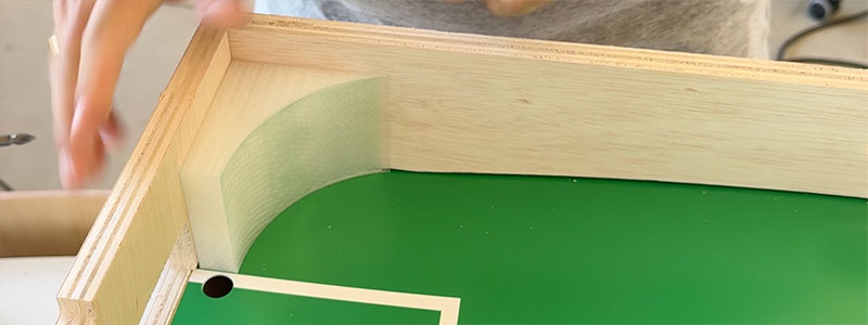
The four corners of the playing field were manufactured using 3D printing. Their purpose is not structural but rather to help redirect the ball toward the hand flipper area whenever it reaches the corners of the playfield.
Since these parts are not required to support any significant loads or mechanical stress, their installation was very straightforward. I fixed them in place using double-sided adhesive tape, which provides more than enough holding strength for normal gameplay.
Once installed, the corners blended seamlessly into the playing surface, helping the ball move more smoothly around the field and preventing situations where it could become trapped or lose momentum.
Corners installation (video size: 0 Mb).
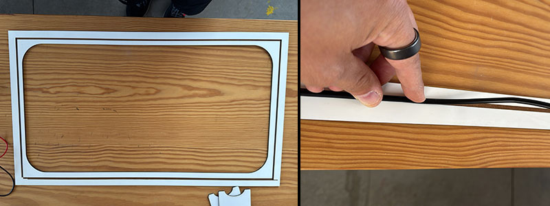
Top cover
Top cover
This was one of the most time-consuming and delicate parts of the assembly process. The top cover is made from 3 mm MDF and includes a laser-engraved pattern on its rear side that acts as a routing guide for the wiring.
The purpose of these engraved channels is to carry the two-wire power cable from the main PCB located in the center of the machine to the two goal-detection PCBs positioned at each end of the playing field. To secure the cable along its path, I used hot glue, which provided a simple and reliable fixing method without requiring additional mechanical fasteners.
Power cable (video size: 0 Mb).
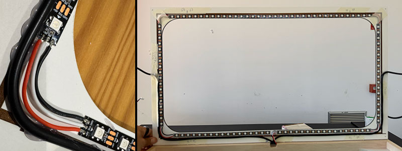
Once the power wiring was in place, I installed the four LED strip sections in their designated positions and connected them together to create a single lighting system.
Special attention had to be paid to the cable exits from each LED section, as they needed to align with the recessed areas designed into the upper wooden structure. This ensured that the cover would sit correctly during the final assembly.
To keep everything organized throughout the process, I used painter's tape to temporarily secure the interconnection wires between LED strip sections and to identify each segment according to its function within the system, distinguishing between the side bands and the goal areas. This made the final wiring and system integration much easier and helped prevent connection mistakes.
Top cover
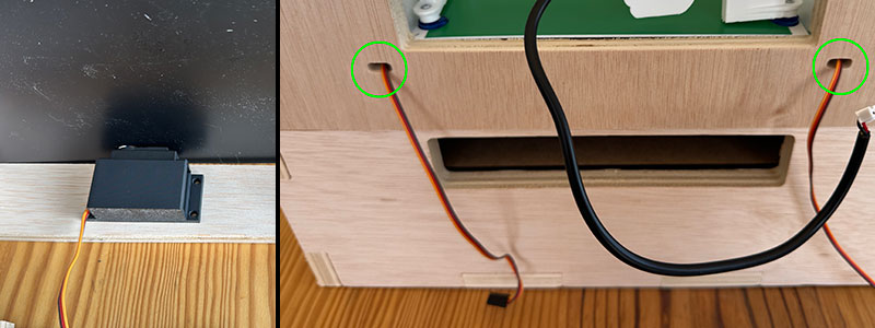
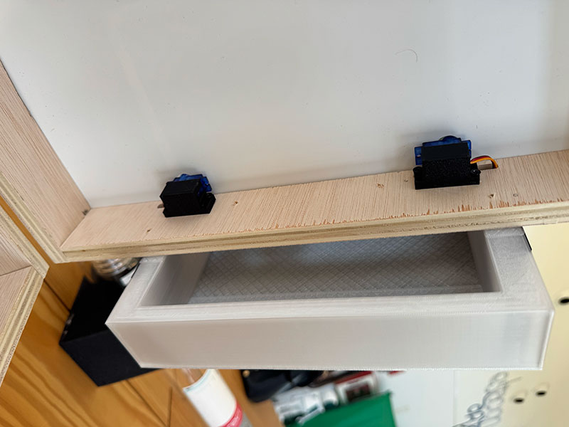
Servos
Servos
The servos were installed using the custom 3D-printed brackets specifically designed for this purpose. These supports allow the motors to be mounted securely while maintaining accurate positioning during gameplay.
The installation process consists of positioning each servo beneath the playing field and carefully adjusting its height until the servo spline protrudes through the corresponding opening in the playfield. Achieving the correct position is important to ensure proper alignment with the hand flipper mechanism.
Once the desired height is reached, the bracket is secured to the wooden structure using screws, leaving the servo firmly mounted and correctly aligned with the game mechanism.
Finally, the servo cable is routed through its dedicated opening and into the interior of the machine, ready to be connected to the control electronics during the final integration stage.
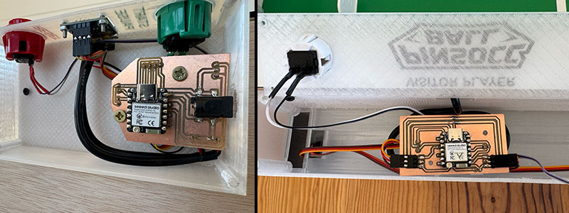
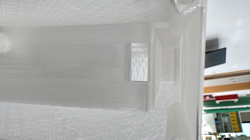
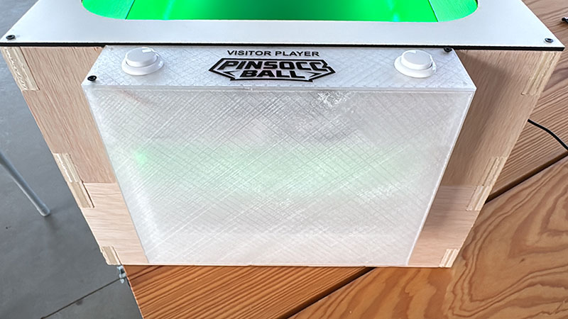
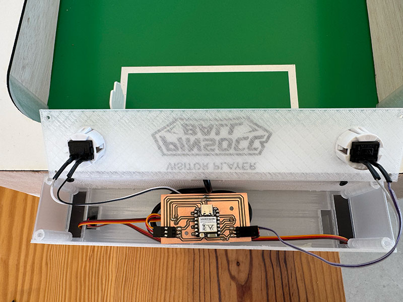
Electronic Cases
Electronic Cases (main and goals)
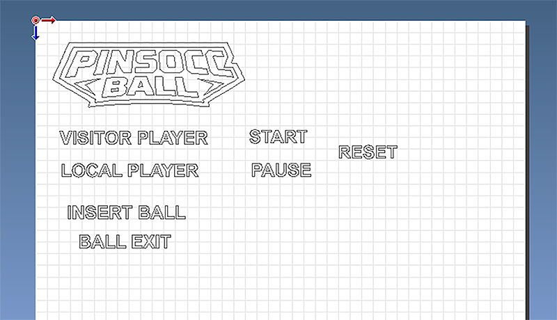
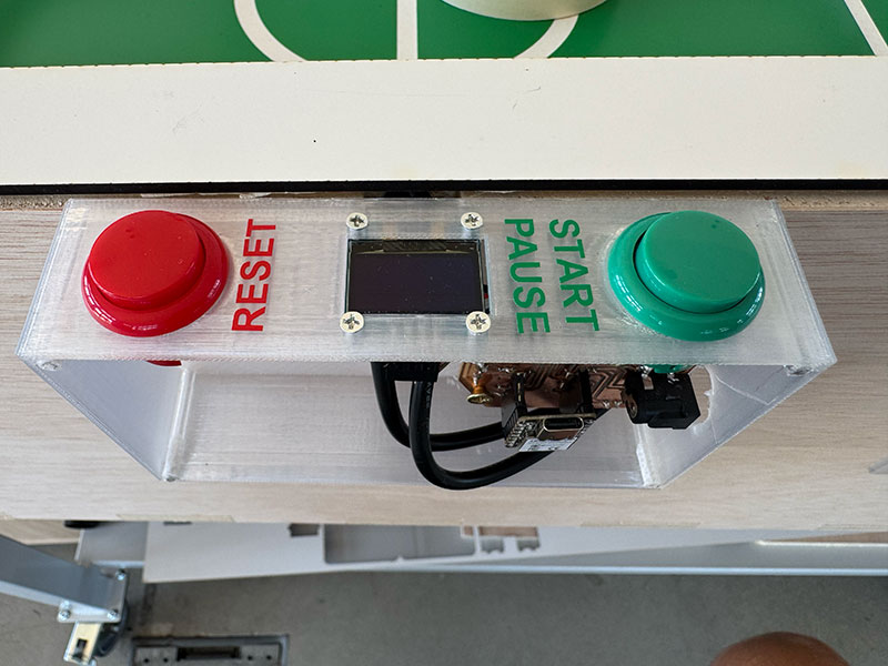
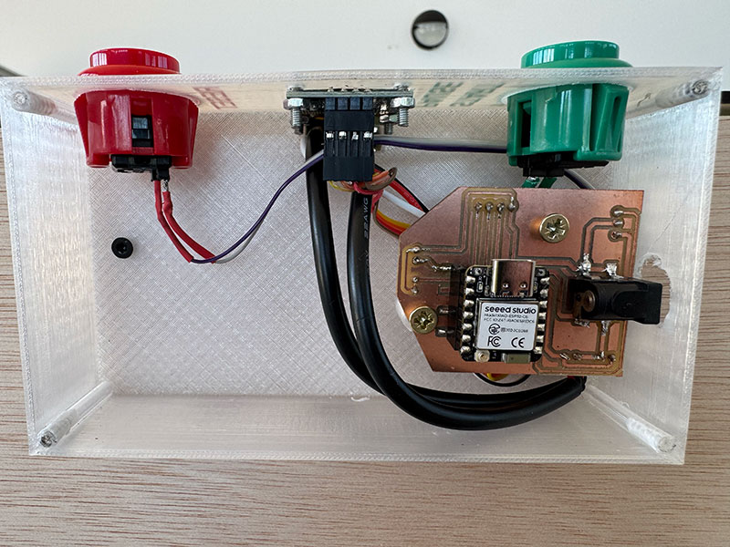
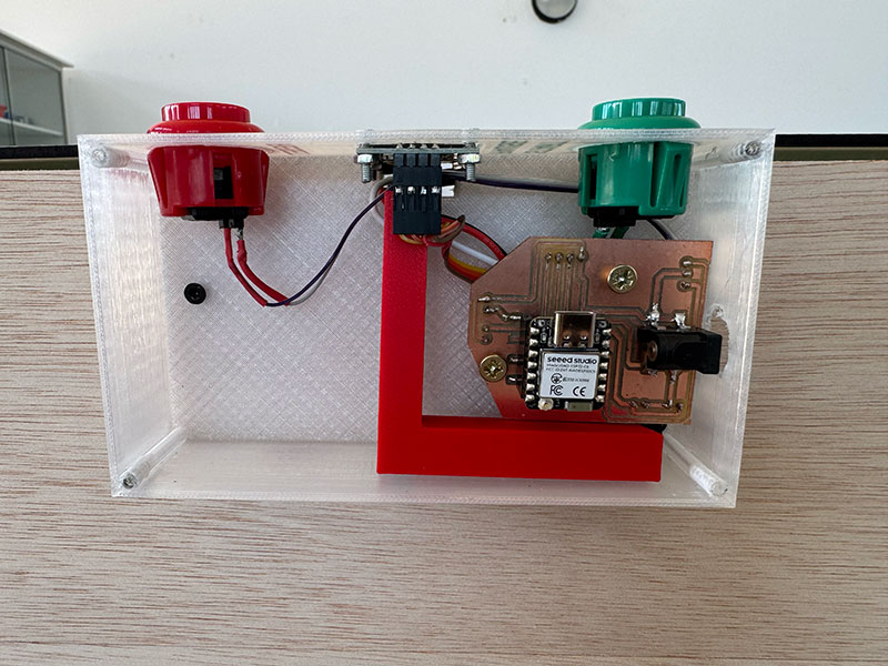
The next step was installing the three 3D-printed enclosures that house all the electronics of the project. These cases contain the PCBs, control buttons, connectors and, in the case of the main enclosure, the OLED display.
Installing each enclosure is straightforward because both the wooden structure and the cases themselves include a rectangular cable pass-through designed to align during assembly. Once properly positioned, each enclosure is secured to the wooden structure using screws.
For the Main Case, I first routed the two cables that connect to the Goal Boxes/Cases. I then installed the OLED display and the control buttons in their dedicated openings. Once all external components were in place, I connected them to the main PCB and secured the board to the integrated mounting points inside the enclosure.
Main case detail (size: 0 Kb -click to enlarge-).Main case detail (size: 0 Kb -click to enlarge-).Main case detail (size: 0 Kb -click to enlarge-).
For each Goal Case, I routed the cables coming from the two servos and guided them to the upper electronics area. I also installed the control buttons and the power cable arriving from the Main Case. Next, I mounted the infrared sensor inside its dedicated holder and routed its cable toward the upper section of the enclosure.
Goal case detail (size: 0 Kb -click to enlarge-).Goal case detail (size: 0 Kb -click to enlarge-).Goal case detail (size: 0 Kb -click to enlarge-).Goal case detail (size: 0 Kb -click to enlarge-).Goal case detail (size: 0 Kb -click to enlarge-).
With all components installed, I connected everything to the corresponding PCB and secured the board to the mounting supports integrated into the enclosure. This left all the electronics protected, organized, and ready for the final integration and testing stages.
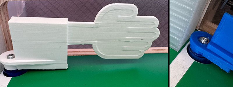
Handflipper
Handflipper
The hand flippers are installed once the servos have been correctly mounted and aligned with the openings in the playing field.
Each hand flipper must be fitted onto the servo spline, ensuring that it is oriented in the correct operating position. It is recommended to verify the servo resting angle beforehand so that all flippers remain properly aligned when the system is in its idle state.
Once the correct position has been confirmed, the hand flipper is secured to the servo using the central screw supplied with the motor. This procedure must be repeated for all four game mechanisms.
After installation, it is advisable to perform a manual movement test to verify that the flippers can travel through their full operating range without interfering with the playing surface or any other mechanical components.
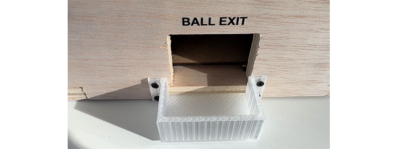
Ball exit box
Ball exit box
The Ball Box is installed at the ball exit area located inside the lower cabinet. This 3D-printed component is responsible for collecting the ball at the end of its return path and positioning it correctly for the next launch.
It is important to verify that the Ball Box is correctly positioned relative to the ramp exits to ensure a smooth transition of the ball into the compartment.
Once installed, it is recommended to perform a simple test by rolling a ball through the return system and confirming that it reaches the Ball Box correctly, without any unwanted friction or blockage points.
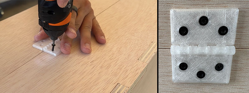
Hingle
Hingle
The final step of the mechanical assembly is the installation of the hinges that connect the upper cabinet to the lower cabinet. These hinges allow the playfield to be opened in a manner similar to a pinball machine, providing access to the interior for maintenance, adjustments, and repairs.
To install them, both sections of the structure must be properly aligned before securing the hinges with screws. Once mounted, it is advisable to verify that the cabinet opens and closes smoothly and that no mechanical interferences are present.
As an optional addition, front latches can be installed to keep the cabinet securely closed during operation. In my case, I added two metal latches on the front side of the machine to prevent accidental opening while playing or transporting the project.
With this step completed, the main mechanical assembly of the project is finished, leaving the machine ready for final testing and commissioning.
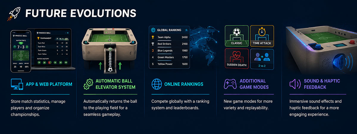
The future evolution of PinSocc Ball is focused on turning the current prototype into a more connected, automated, and engaging game experience.
One possible improvement is an app and web platform where players could store match statistics, check previous results, manage users, and organize small championships or tournaments.
Another important evolution would be an automatic ball elevator system, using a worm gear mechanism to return the ball to the playing field without manual intervention.
The project could also include online rankings, additional game modes, and sound or haptic feedback to make the gameplay more immersive, competitive, and replayable.
License
CC BY-NC-SA 4.0: Attribution - NonCommercial - ShareAlike 4.0 International


