Week 4
Embedded Programming
Contents
Week questions/tasks
Starting Point
For this assignment, FabLab León provided us with a QPAD-XIAO board: QPAD-XIAO repository ↗️.
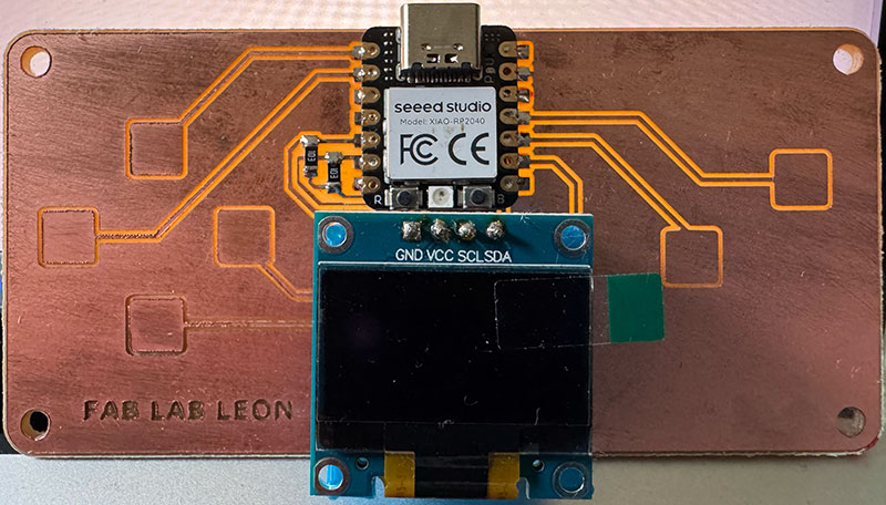
The QPAD-XIAO is a learning-oriented tool that helps you get started with embedded programming and basic user-interface design. It includes a microcontroller (Seeed XIAO RP2040 module), an OLED screen, and six capacitive touch pads, so it’s perfect to practice inputs and outputs in a single compact device.
In my case, I was starting from scratch: I had never programmed a board before, and I didn’t even have Arduino IDE installed on my computer. So this week wasn’t just about “running examples”, but about understanding the full workflow: setting up the tools, loading code, installing libraries, and then modifying programs until the board behaved the way I wanted.
Group assignment
Due to the distance to Fab Lab León ↗️ (110 km.), this week for the group Assignment we have decided to divide the work and carry it out, in my case, in the Fab Lab of my city (Fab Lab Ponferrada ↗️).
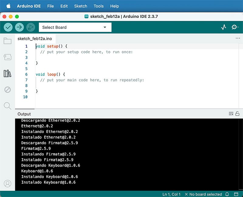
As part of the group assignment, and considering that I had no previous experience programming boards —as I mentioned earlier— I first had to install Arduino IDE from scratch and configure it specifically for the QPAD-XIAO.
It wasn’t just a matter of opening the software and starting to code. I had to understand how to add the board support package, install the required components, and make sure the environment correctly recognized the hardware.
Later on, in order to run the MicroPython tests, I had to change the board’s firmware, switching from Arduino to MicroPython and working in that environment for a while. After finishing the tests, I flashed it back to Arduino again.
Going back and forth between environments was actually very helpful. It helped me lose the initial fear of “breaking” the board and made me realize that the hardware remains the same — what really changes is the way you program it.
1 Arduino IDE installation
I started by installing Arduino IDE for Mac OS X (ARM), following the first part of the official Seeed Studio tutorial: XIAO RP2040 with Arduino ↗️ .
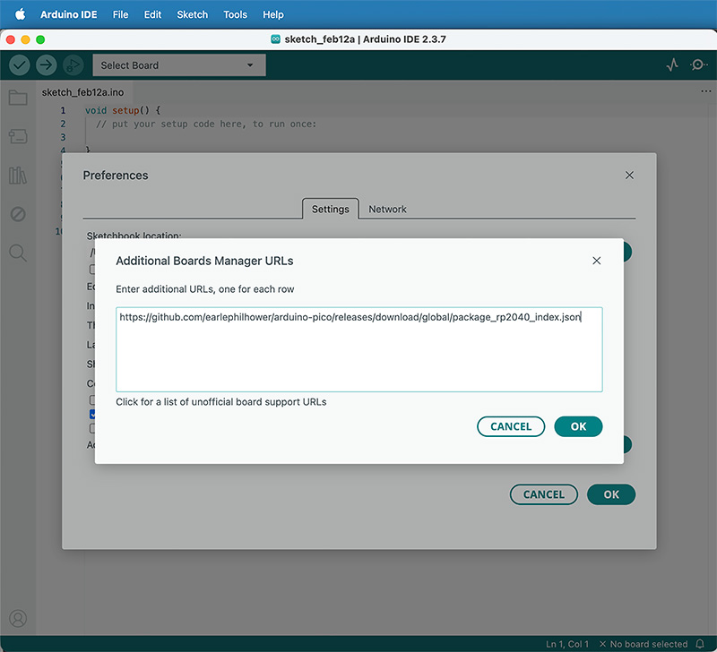
After installing Arduino IDE, I needed to add the RP2040 board package. In Preferences / Settings, I added this URL to “Additional Boards Manager URLs”:
https://github.com/earlephilhower/arduino-pico/releases/download/global/package_rp2040_index.json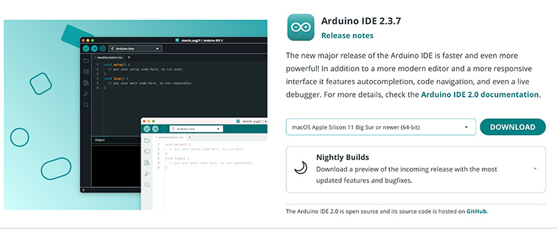
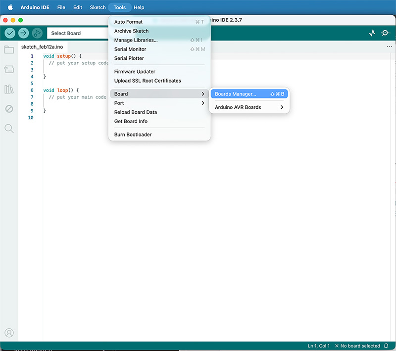
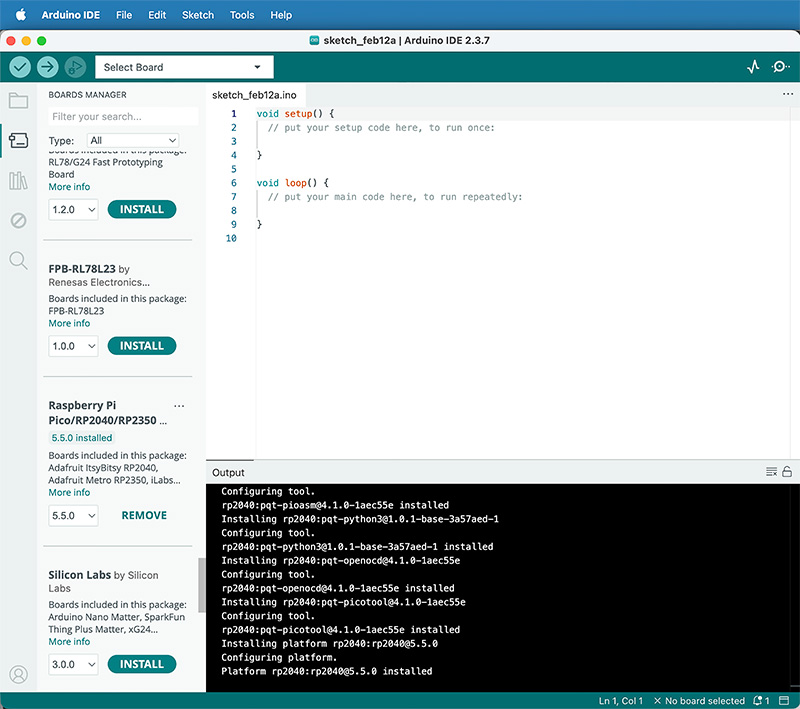
2 Adding RP2040 support (Boards Manager)
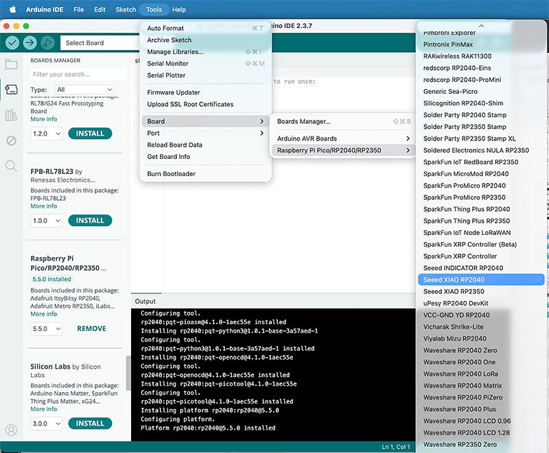
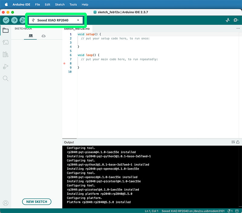
Then I opened Tools → Boards → Boards Manager and installed the package “Raspberry Pi Pico/RP2040/RP2350 …” (v5.5.0). Once installed, I selected: Tools → Boards → Raspberry Pi Pico/RP2040/2350 → Seeed XIAO RP2040.
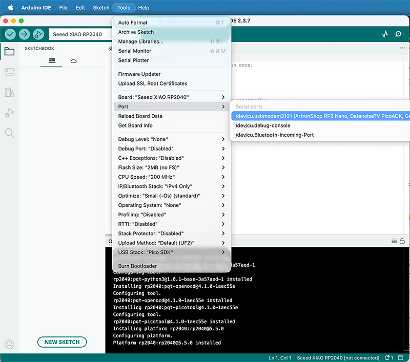
Finally, I connected the board via USB and selected the correct serial port in Tools → Port. At that point Arduino IDE recognized it properly.
3 Seeed Studio XIAO RP2040 with MicroPython
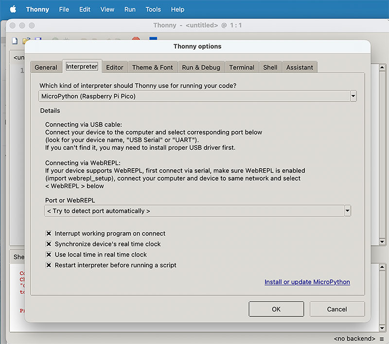
After getting the board running with Arduino, I wanted to test the same hardware using MicroPython. The idea was to compare both workflows and see how it feels to program the RP2040 with a more “Python-like” approach.
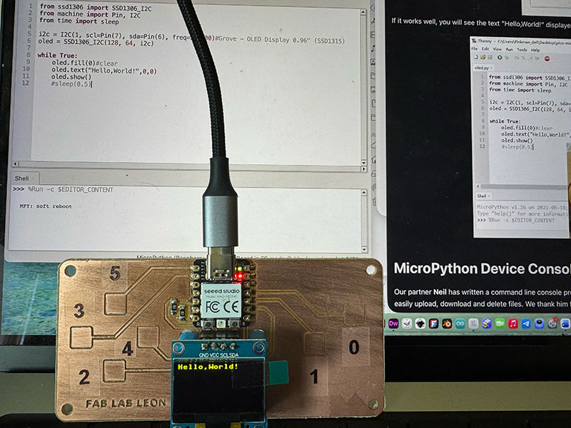
I followed the official Seeed Studio tutorial XIAO RP2040 with MicroPython ↗️ and Pablo's tutorial ↗️. The process is different from Arduino because you first need to flash the MicroPython firmware to the board, and then you work from a shell/REPL to run code and test small changes quickly.
Once MicroPython was installed, I ran the two example scripts from the tutorial.
4 Seeed Studio XIAO RP2040 back to Arduino
Finally, I flashed the board back to Arduino following the Seeed Studio Arduino tutorial again: XIAO RP2040 with Arduino ↗️ . This last step was useful because it confirmed how flexible the RP2040 ecosystem is: the same board can move between different programming environments just by changing the firmware and toolchain.
Individual assignment
Datasheet RP2040 (Raspbery Pi) & Seeed Studio XIAO RP2040 & QPAD-xiao
To properly understand the board we are programming, I first reviewed the official RP2040 datasheet and then compared that information with the physical pinout and hardware design of the Seeed Studio XIAO RP2040.
It is important to distinguish between the microcontroller itself (RP2040) and the development board (XIAO RP2040). The datasheet describes everything the chip is capable of, while the board only exposes a subset of those features through its compact hardware design.
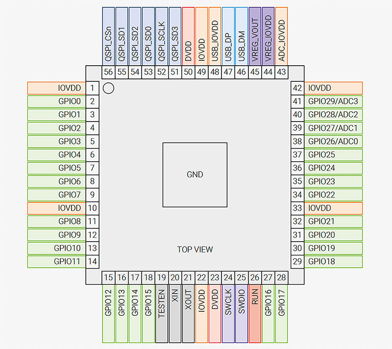
1 General Architecture (datasheet pages 15–17)
The RP2040 is built around a dual-core ARM Cortex-M0+ processor running at up to 133 MHz. It includes 264 kB of internal SRAM and uses external QSPI Flash memory. In the case of the XIAO RP2040, the board integrates 2 MB of external Flash.
According to the datasheet, the chip provides:
- 30 multifunction GPIO pins
- 12-bit ADC
- Up to 16 PWM channels
- 2× SPI, 2× I2C, 2× UART
- USB 1.1 Host/Device controller
- Programmable I/O (PIO) subsystem
These are the theoretical capabilities of the microcontroller. The board, however, exposes only part of this functionality.
2 GPIO – Microcontroller RP2040 (pages 207–211, 629–632) vs Seeed XIAO RP2040 vs QPAD-xiao
Internally, the RP2040 provides 30 GPIO pins (GPIO0–GPIO29), all operating at 3.3V. Each pin can be configured as digital input or output and multiplexed for communication peripherals (SPI, I2C, UART, PWM, etc.).
The XIAO RP2040 board does not expose all 30 GPIO. Instead, it makes available the following pins:
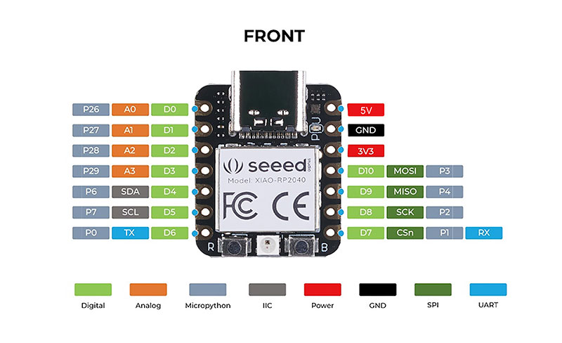
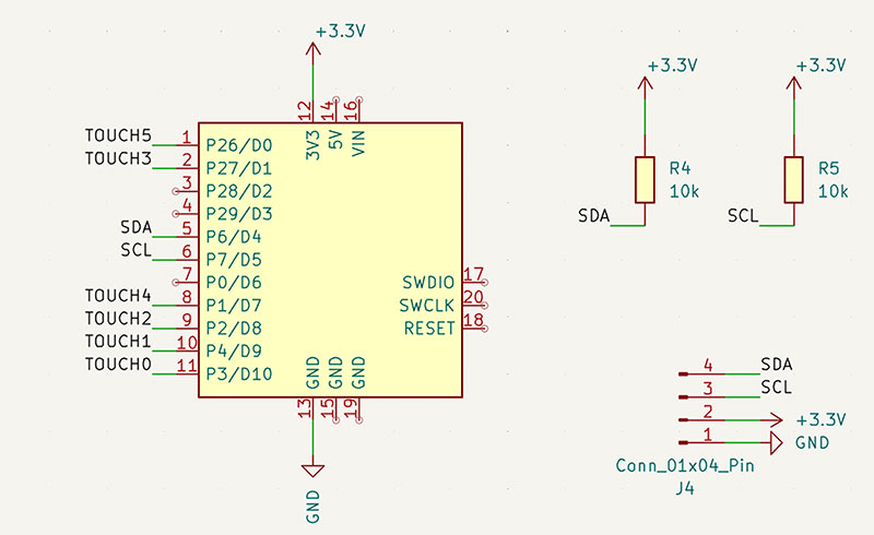
GPIO available on XIAO RP2040 & QPAD-xiao mapping
| RP2040 GPIO | Seeed XIAO Pin | QPAD-XIAO Function |
|---|---|---|
| GPIO26 | D0 | Touch pad 5 |
| GPIO27 | D1 | Touch pad 3 |
| GPIO28 | D2 | Free |
| GPIO29 | D3 | Free |
| GPIO6 | D4 | Display SDA (I2C) |
| GPIO7 | D5 | Display SCL (I2C) |
| GPIO0 | D6 | Free |
| GPIO1 | D7 | Touch pad 4 |
| GPIO2 | D8 | Touch pad 2 |
| GPIO4 | D9 | Touch pad 1 |
| GPIO3 | D10 | Touch pad 0 |
This means that although the chip supports 30 GPIO, the board physically exposes
11 main digital pins (D0–D10).
It also explains why the capacitive touch pins used in the QPAD-xiao correspond to GPIO 26, 27, 1, 2, 4 and 3.
3 Analog Inputs – ADC (pages 16, 634–636)
The RP2040 integrates a 12-bit ADC with four external analog channels mapped to GPIO26–GPIO29.
On the XIAO RP2040 board, these are exposed as:
4 Analog inputs on XIAO RP2040
| XIAO Pin | GPIO | ADC Channel |
|---|---|---|
| A0 / D0 | GPIO26 | ADC0 |
| A1 / D1 | GPIO27 | ADC1 |
| A2 / D2 | GPIO28 | ADC2 |
| A3 / D3 | GPIO29 | ADC3 |
In this case, the board exposes all four ADC channels available on the chip. The input voltage range is 0–3.3V.
4 PWM (pages 15, 207)
The RP2040 provides 8 PWM slices, each with two channels (A/B), allowing up to 16 PWM outputs internally.
PWM (Pulse Width Modulation) is a technique used to simulate an analog output using a digital signal. Instead of changing voltage, the signal rapidly switches between LOW and HIGH, and the percentage of time it stays HIGH (duty cycle) determines the effective power delivered.
PWM is typically used to:
- Control LED brightness
- Regulate motor speed
- Drive servos
Although the chip supports 16 PWM channels, the usable ones depend on the GPIO physically exposed by the XIAO board.
5 Communication Interfaces
The RP2040 allows flexible peripheral multiplexing. The XIAO RP2040 defines a practical mapping for communication:
- I2C: D4 (SDA – GPIO6), D5 (SCL – GPIO7)
- UART: D6 (TX – GPIO0), D7 (RX – GPIO1)
- SPI: D8 (SCK – GPIO2), D9 (MISO – GPIO4), D10 (MOSI – GPIO3)
The chip would allow alternative configurations, but the board standardizes these assignments for simplicity.
6 Electrical Characteristics (pages 628–636)
According to the datasheet, the RP2040 operates at 3.3V, with configurable GPIO drive strengths (2, 4, 8 or 12 mA). The ADC resolution is 12 bits and the logic levels are defined for 3.3V operation.
The XIAO RP2040 board respects these limits and includes voltage regulation and USB power management to ensure stable operation.
Conclusion
Reviewing the datasheet alongside the board documentation helped me understand the difference between what the RP2040 chip is capable of and what the XIAO RP2040 board physically provides.
The microcontroller offers 30 GPIO and extensive flexibility, while the board exposes a compact and practical subset suitable for embedded development. Understanding this distinction is essential when designing circuits or planning future projects beyond the limitations of this specific board.
Program a board to interact and communicate
1 First test: Blink
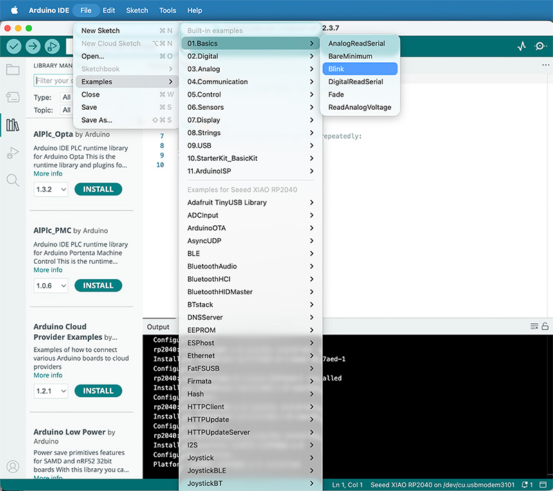
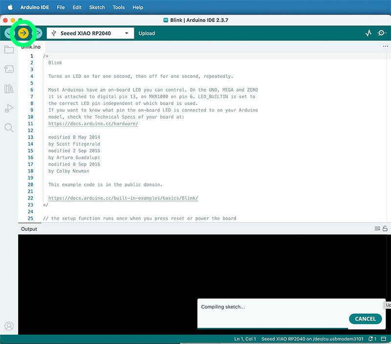
With the XIAO with Arduino setup, to verify everything worked, I uploaded the built-in example in Arduino IDE File → Examples → Basics → Blink.
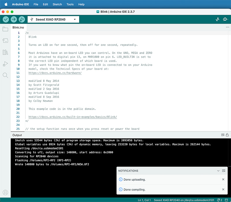
The LED started blinking every 1 second, confirming that compilation and upload were working.
I changed the delay() values a few times to confirm the board responded immediately to code changes.
2 QPAD-XIAO Blink + RGB sequence
Next, I uploaded the Blink example from the QPAD-XIAO repository. This one blinks the green LED every 500 ms. After that, I modified the loop so the RGB LEDs turn on sequentially: red for 500 ms, then blue for 500 ms, then green for 500 ms.
This simple change made it much easier to visually confirm that the board has three separate LEDs and that each one is controlled independently.
Arduino code · sketch_feb12c_3leds.ino Show code
#define PIN_RED 17
#define PIN_GREEN 16
#define PIN_BLUE 25

void setup() {
  pinMode(PIN_RED, OUTPUT);
  pinMode(PIN_GREEN, OUTPUT);
  pinMode(PIN_BLUE, OUTPUT);

  digitalWrite(PIN_RED, HIGH);
  digitalWrite(PIN_GREEN, HIGH);
  digitalWrite(PIN_BLUE, HIGH);
}

void loop() {
  // Enciendo el rojo y lo apago a los 500ms
  // I turn on the red light and turn it off after 500ms
  digitalWrite(PIN_RED, LOW);
  delay(500);
  digitalWrite(PIN_RED, HIGH);

  // Hago lo mismo con el Verde
  // I do the same with the green
  digitalWrite(PIN_GREEN, LOW);
  delay(500);
  digitalWrite(PIN_GREEN, HIGH);

  // Y por último el Azul
  // And finally, Blue
  digitalWrite(PIN_BLUE, LOW);
  delay(500);
  digitalWrite(PIN_BLUE, HIGH);
  // Y vuelvo a empezar
  // Loop
}
You can download this .ino code in the downloads section at the bottom of this page
High quality video available on my YouTube channel ↗️.
3 OLED display test + libraries
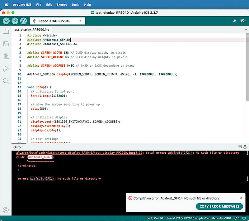
I then downloaded and uploaded test_display_RP2040.ino from the QPAD-XIAO examples.
At first it didn’t compile because I was missing the libraries <Adafruit_GFX.h> and <Adafruit_SSD1306.h>.
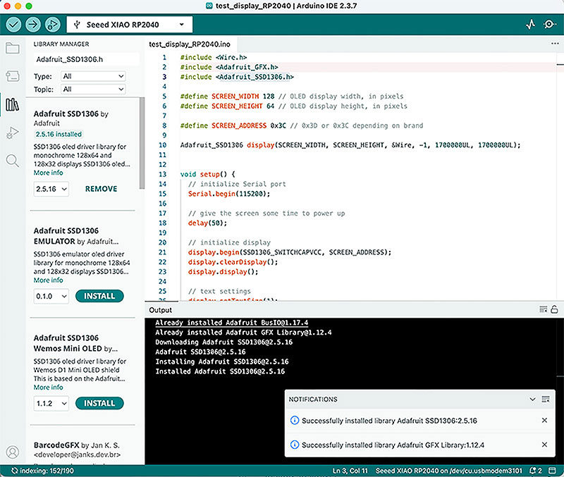
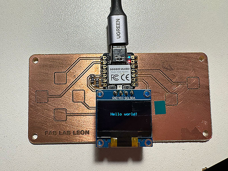
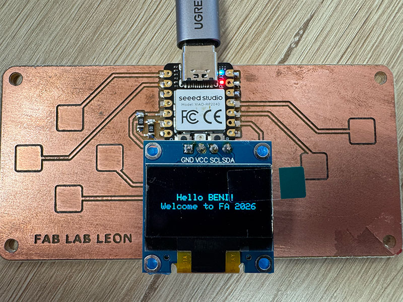
I installed both libraries using the Arduino Library Manager (including the dependencies it suggested). After that, the sketch compiled and the OLED displayed “Hello World”. I then customized the output to show two lines: “Hello BENI!” and “Welcome to FA 2026”.
It is also possible to add external libraries from the option: Sketch / Include Library / Add .zip library.
Arduino code · Hello BENI - Welcome to FA 2026 Show code
#include
#include
#include

#define SCREEN_WIDTH 128 // OLED display width, in pixels
#define SCREEN_HEIGHT 64 // OLED display height, in pixels

#define SCREEN_ADDRESS 0x3C // 0x3D or 0x3C depending on brand

Adafruit_SSD1306 display(SCREEN_WIDTH, SCREEN_HEIGHT, &Wire, -1, 1700000UL, 1700000UL);


void setup() {
  // initialize Serial port
  Serial.begin(115200);

  // give the screen some time to power up
  delay(50);

  // initialize display
  display.begin(SSD1306_SWITCHCAPVCC, SCREEN_ADDRESS);
  display.clearDisplay();
  display.display();

  // text settings
  display.setTextSize(1);
  display.setTextColor(SSD1306_WHITE);
}


void loop() {
  // clear the buffer
  display.clearDisplay();
  // pick a position
  display.setCursor(28, 25);
  // write to buffer
  display.print("Hello BENI!");
  // move the position
  display.setCursor(10, 35);
  // write more text
  display.print("Welcome to FA 2026");
  // send buffer
  display.display();
}
You can download this .ino code in the downloads section at the bottom of this page
4 Touch pads test + improved interaction
After the display test, I uploaded test_touch_RP2040.ino. When running it, I saw the green LED react when touching the pads (only the 0 button). In the Serial Monitor (on ArduinoIDE), I could also see that all six touch pads were being detected correctly.
High quality video available on my YouTube channel ↗️.
I modified the code so the interaction was clearer: the green LED stays on while any of the six buttons is being touched, and at the same time the OLED shows which button is currently pressed. This made the project feel like a real little interface: touch input, visual feedback on-screen, and LED feedback.
High quality video available on my YouTube channel ↗️.
Arduino code · Led & info screen 6 touch buttons (test_touch_RP2040_BENI.ino) Show code
#include
#include
#include

// ================== LED PINS ==================
// Pines del LED RGB / RGB LED pins
#define PIN_RED   17
#define PIN_GREEN 16
#define PIN_BLUE  25

// ================== TOUCH SETTINGS ==================
// Número de sensores táctiles / Number of touch sensors
#define N_TOUCH 6
// Umbral para detectar toque / Threshold to detect touch
#define THRESHOLD 6

// Pines táctiles / Touch pins
int touch_pins[N_TOUCH] = {3, 4, 2, 27, 1, 26};
// Valores medidos / Measured values
int touch_values[N_TOUCH] = {0, 0, 0, 0, 0, 0};

// Estados actuales y anteriores / Current and previous states
bool pin_touched_now[N_TOUCH]  = {false, false, false, false, false, false};
bool pin_touched_past[N_TOUCH] = {false, false, false, false, false, false};

// ================== OLED SETTINGS ==================
#define SCREEN_WIDTH 128
#define SCREEN_HEIGHT 64
#define SCREEN_ADDRESS 0x3C

Adafruit_SSD1306 display(SCREEN_WIDTH, SCREEN_HEIGHT, &Wire, -1, 1700000UL, 1700000UL);


// ====================================================
// Function to update touch sensors
// Función para actualizar los sensores táctiles
// ====================================================
void update_touch() {

  int t;
  int t_max = 200;
  int p;

  for (int i = 0; i < N_TOUCH; i++) {

    p = touch_pins[i];

    // Discharge pin (set LOW)
    // Descargar el pin (poner a LOW)
    pinMode(p, OUTPUT);
    digitalWriteFast(p, LOW);

    delayMicroseconds(25); // Stabilization delay / Tiempo de estabilización

    // Enable internal pull-up
    // Activar resistencia pull-up interna
    pinMode(p, INPUT_PULLUP);

    // Measure time to rise
    // Medir tiempo hasta subir a HIGH
    t = 0;
    while (!digitalReadFast(p) && t < t_max) {
      t++;
    }

    touch_values[i] = t;

    // Save previous state
    // Guardar estado anterior
    pin_touched_past[i] = pin_touched_now[i];

    // Compare with threshold
    // Comparar con el umbral
    pin_touched_now[i] = (touch_values[i] > THRESHOLD);
  }
}


// ====================================================
// SETUP
// ====================================================
void setup() {

  // Initialize Serial communication
  // Inicializar comunicación Serial
  Serial.begin(115200);
  delay(50);

  Serial.println("Touch system initialized");
  Serial.println("Sistema tactil iniciado");

  // Initialize OLED display
  // Inicializar pantalla OLED
  display.begin(SSD1306_SWITCHCAPVCC, SCREEN_ADDRESS);
  display.clearDisplay();
  display.display();

  display.setTextColor(SSD1306_WHITE);
  display.setTextSize(2); // Larger text / Texto más grande

  // Initialize RGB LED (active LOW)
  // Inicializar LED RGB (activo en LOW)
  pinMode(PIN_RED, OUTPUT);
  pinMode(PIN_GREEN, OUTPUT);
  pinMode(PIN_BLUE, OUTPUT);

  digitalWrite(PIN_RED, HIGH);
  digitalWrite(PIN_GREEN, HIGH);
  digitalWrite(PIN_BLUE, HIGH);
}


// ====================================================
// LOOP
// ====================================================
void loop() {

  update_touch();

  int touchedIndex = -1;

  // Check which button is pressed
  // Comprobar qué botón está pulsado
  for (int i = 0; i < N_TOUCH; i++) {
    if (pin_touched_now[i]) {
      touchedIndex = i;
      break;
    }
  }

  // ===== SERIAL MONITOR OUTPUT =====
  // Print raw sensor values
  // Mostrar valores crudos de los sensores
  Serial.print("Values: ");
  for (int i = 0; i < N_TOUCH; i++) {
    Serial.print(touch_values[i]);
    Serial.print(" ");
  }

  if (touchedIndex >= 0) {
    Serial.print("  --> Button pressed: ");
    Serial.println(touchedIndex);
  } else {
    Serial.println("  --> No button pressed");
  }

  // ===== LED + DISPLAY CONTROL =====
  if (touchedIndex >= 0) {

    // Turn ON green LED
    // Encender LED verde
    digitalWrite(PIN_GREEN, LOW);

    // Show pressed button on display
    // Mostrar botón pulsado en pantalla
    display.clearDisplay();
    display.setCursor(15, 25);
    display.print("Touch: ");
    display.print(touchedIndex);
    display.display();
  }
  else {

    // Turn OFF LED
    // Apagar LED
    digitalWrite(PIN_GREEN, HIGH);

    // Clear screen
    // Limpiar pantalla
    display.clearDisplay();
    display.display();
  }

  delay(50); // Slow down Serial output / Reducir velocidad de impresión
}
You can download this .ino code in the downloads section at the bottom of this page
5 Seeed Studio XIAO RP2040 with MicroPython
Once MicroPython was installed (view on group assignment), I ran the two example scripts from the tutorial.
After that, I did the same thing I had done with Arduino: I tested the MicroPython examples available in the QPAD-XIAO repository. The goal was to check that the board behaved consistently in this environment and to see how the code structure changes when working in MicroPython.
High quality video available on my YouTube channel ↗️.
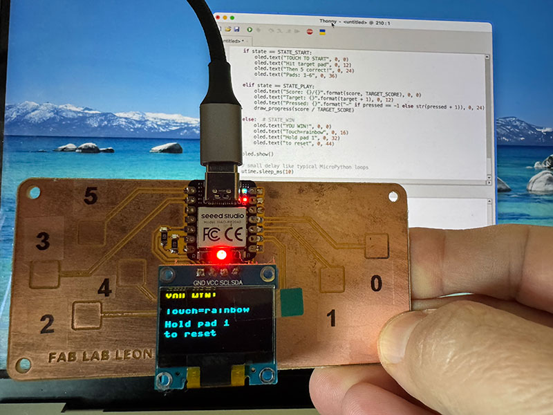
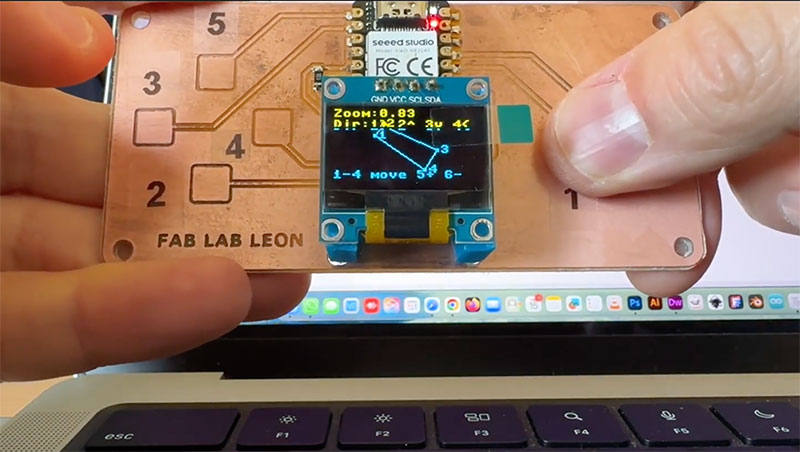
6 Score display board for my final proyect
As part of this week's activities, and thinking that I can now apply to the final project, I have simulated a possible scoreboard in the final project development section.
Final project development - Week04 sectionReflection
This week was my first real hands-on experience programming a board. I started with zero background in microcontrollers, and by the end I felt much more confident testing, modifying, and understanding what the code was doing on the hardware.
With Arduino, I learned the basic structure of an embedded program and how to connect inputs and outputs: LEDs, the OLED display, and the touch pads. It felt like a solid and organized way to build a foundation.
Switching to MicroPython felt different. It’s the same hardware, but the workflow is faster and more direct—especially when you can test things quickly from the shell. The best part was realizing I can switch environments without being afraid of “breaking” the board: I’m just changing how I program it.
Trying both Arduino and MicroPython in the same week helped me understand that there isn’t a single “right” way to work with a microcontroller—different tools fit different goals.
Original code files for this documentation
Files for download
- 3 led ON (sketch_feb12c_3leds.ino) INO · 0,6 Kb
- Led ON with all touch (test_touch_RP2040_all.ino) INO · 2 Kb
- Hello Beni! (test_display_RP2040_hellobeni.ino) INO · 1 Kb
- Screen show the touch (test_touch_RP2040_BENI.ino) INO · 4 Kb
- HTML (& .css + .js) code viewer ZIP · 5 Kb
Credits
All texts were written in Spanish and translated into English using Google Translate and ChatGPT.