Week 17: Wildcard Week
Assignment
Design and produce something with a digital process (incorporating computer-aided design and manufacturing) not covered in another assignment, documenting the requirements that your assignment meets, and including everything necessary to reproduce it.
Laser-Cut Metal Origami
For this week’s wildcard assignment, I decided to experiment with laser-cut metal origami.
I chose the Waterbomb Tessellation by Eric Gjerde, a classic pattern that transforms a flat sheet into a complex, three-dimensional form through a combination of mountain and valley folds
Understanding the Crease Pattern
Before drawing the pattern in Fusion, I first needed to understand how the Waterbomb Tessellation is constructed.
The pattern follows a simple folding rule:
- Horizontal and vertical grid lines are mountain folds.
- Diagonal lines are valley folds.
These two types of folds work together to allow the flat sheet to collapse into a three-dimensional form.
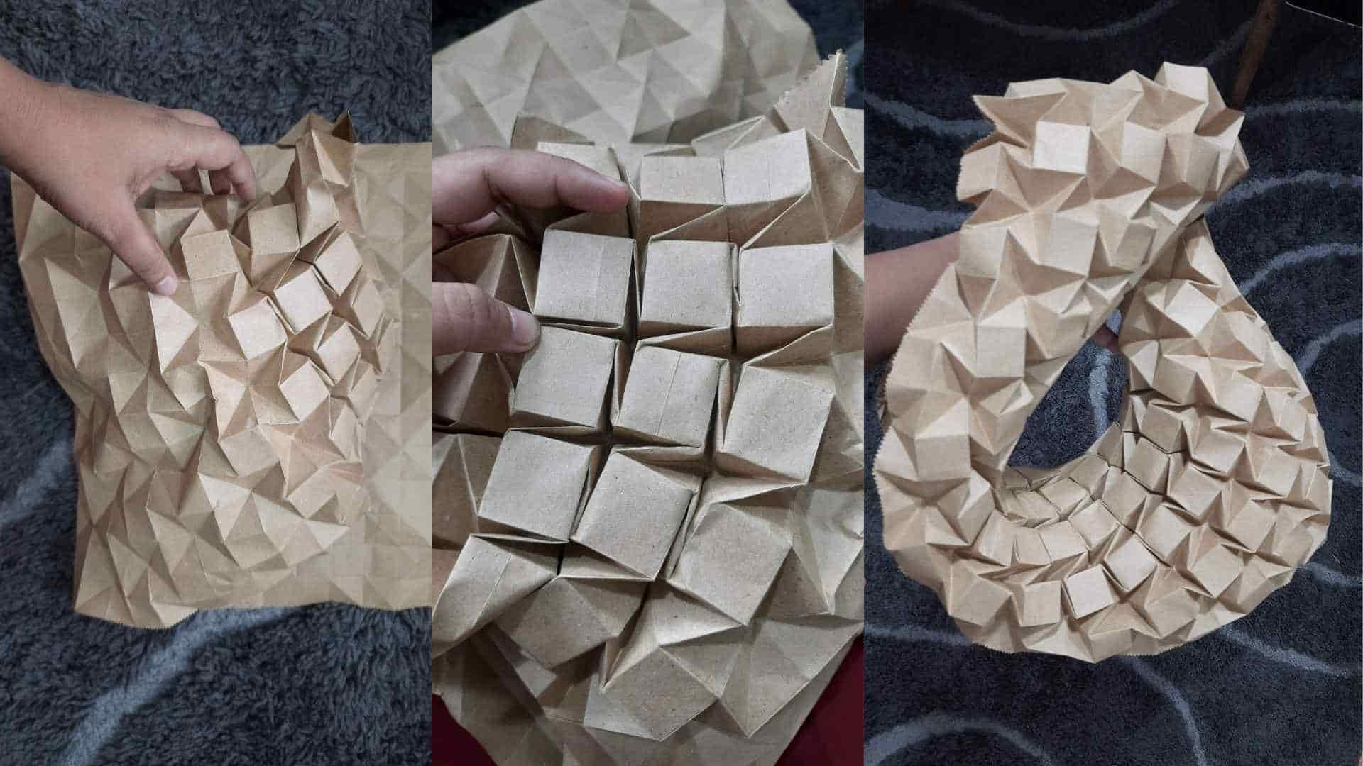
Paper prototype of the Waterbomb Tessellation folded prior to the metal experiment.
Constructing the Pattern
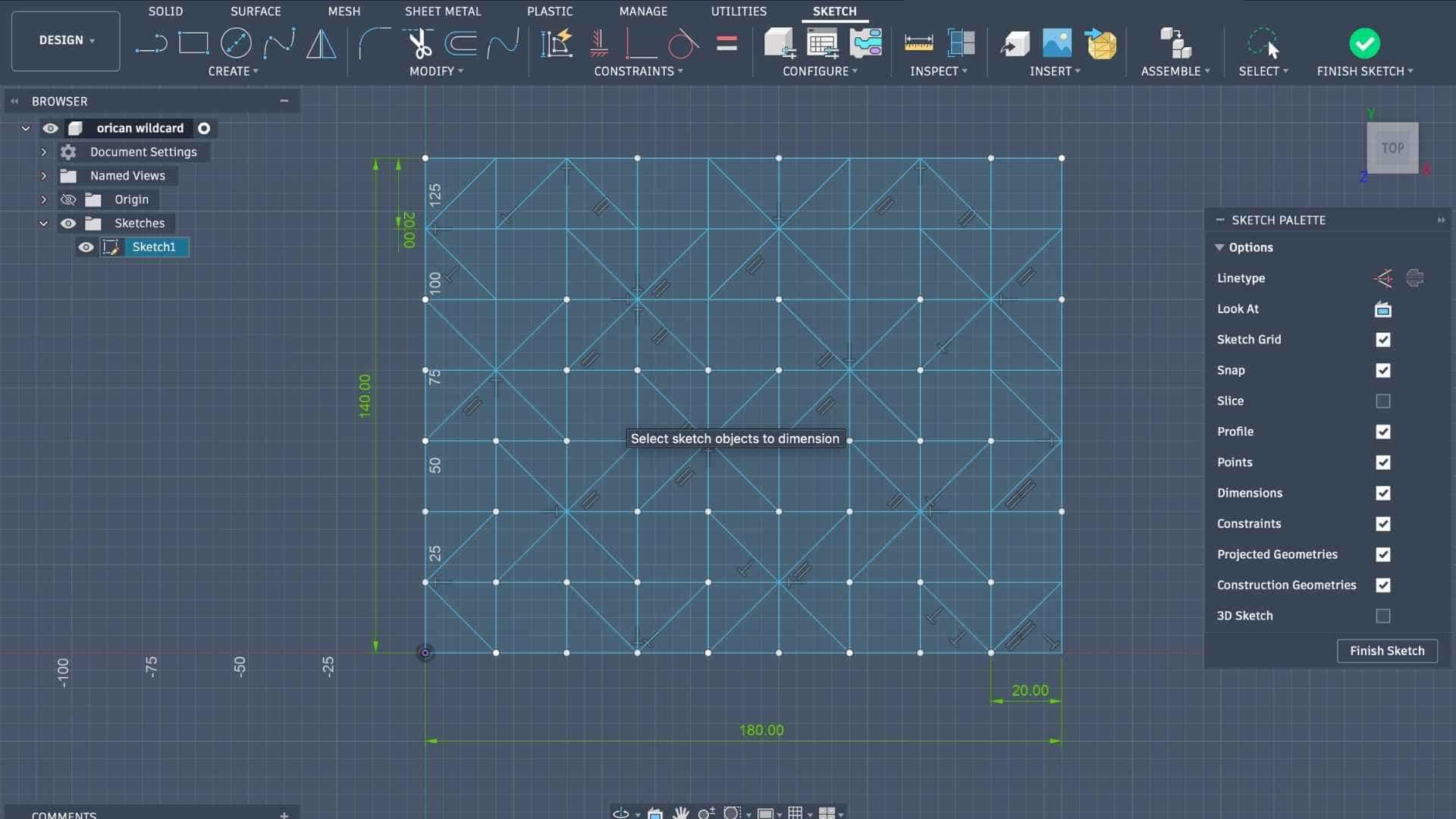
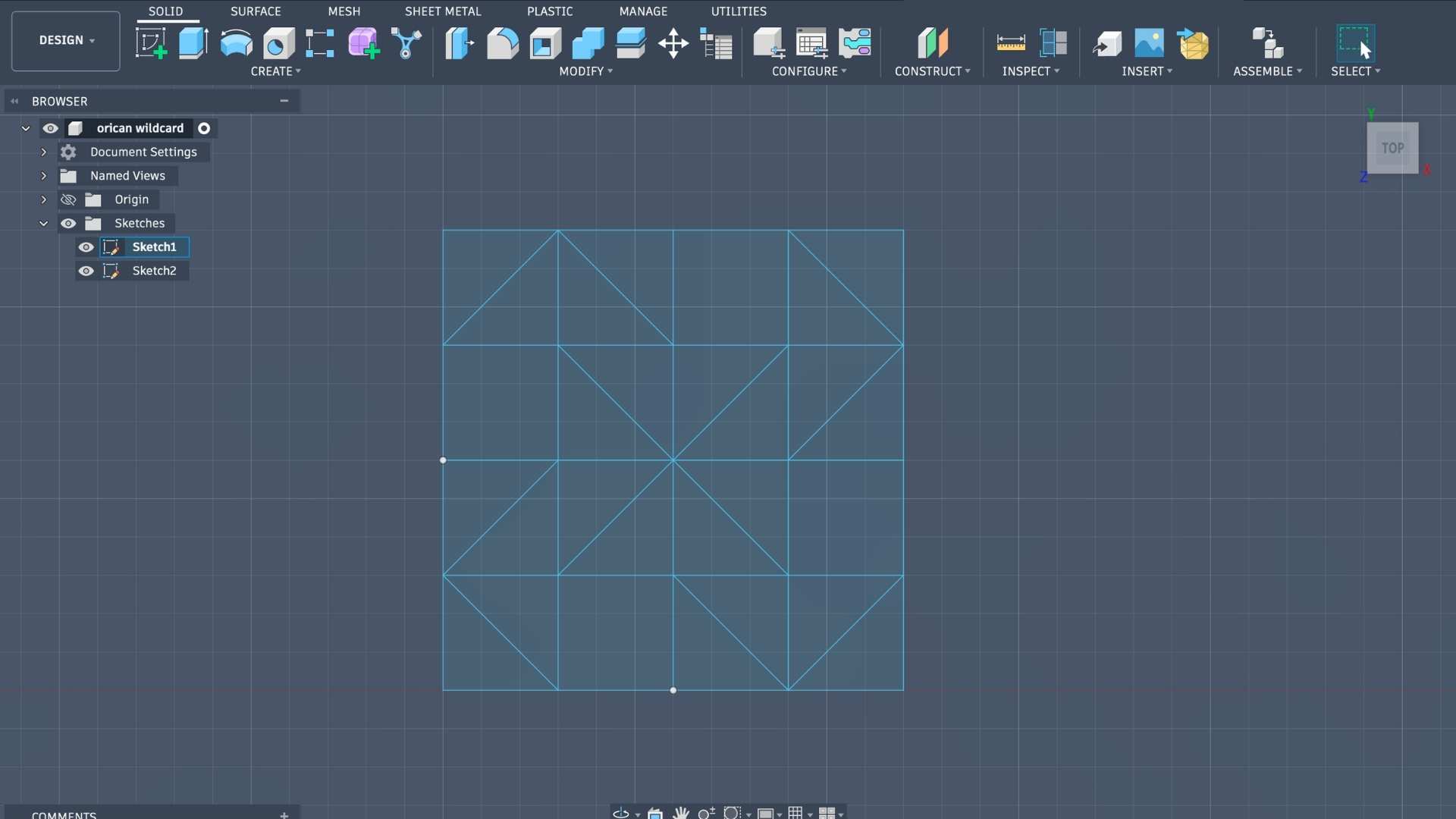
I began by creating a square grid in Fusion.
To generate a waterbomb unit, select any square within the grid and imagine it as the center of a 2 × 2 block of squares. From the corners of the selected square, draw diagonals that pass through the surrounding 2 × 2 region. These diagonals can be oriented either clockwise or counterclockwise, depending on the tessellation arrangement.
Repeating this operation across the grid creates the complete Waterbomb Tessellation.
The process can be summarized as:
- Create a square grid.
- Select a square.
- Draw diagonals through the surrounding 2 × 2 block.
- Repeat across the grid.
- Assign horizontal and vertical lines as mountain folds.
- Assign diagonal lines as valley folds.
How Do You Know Which Way to Fold?
In this pattern, the fold directions are straightforward:
- Mountain folds: all horizontal and vertical grid lines.
- Valley folds: all diagonal lines.
This makes the crease pattern easier to read because the fold direction is determined by the line type rather than needing to memorize individual folds.
Beginner Tip: If you are recreating this pattern for the first time, fold it in paper first.
Preparing the Pattern for Origami Simulator
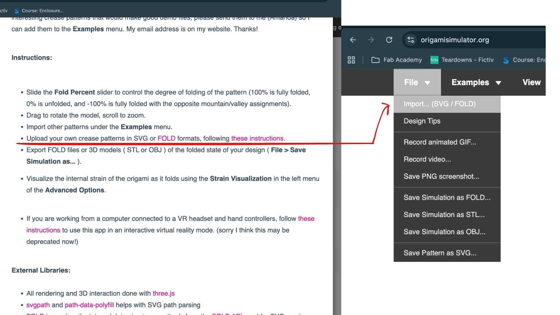
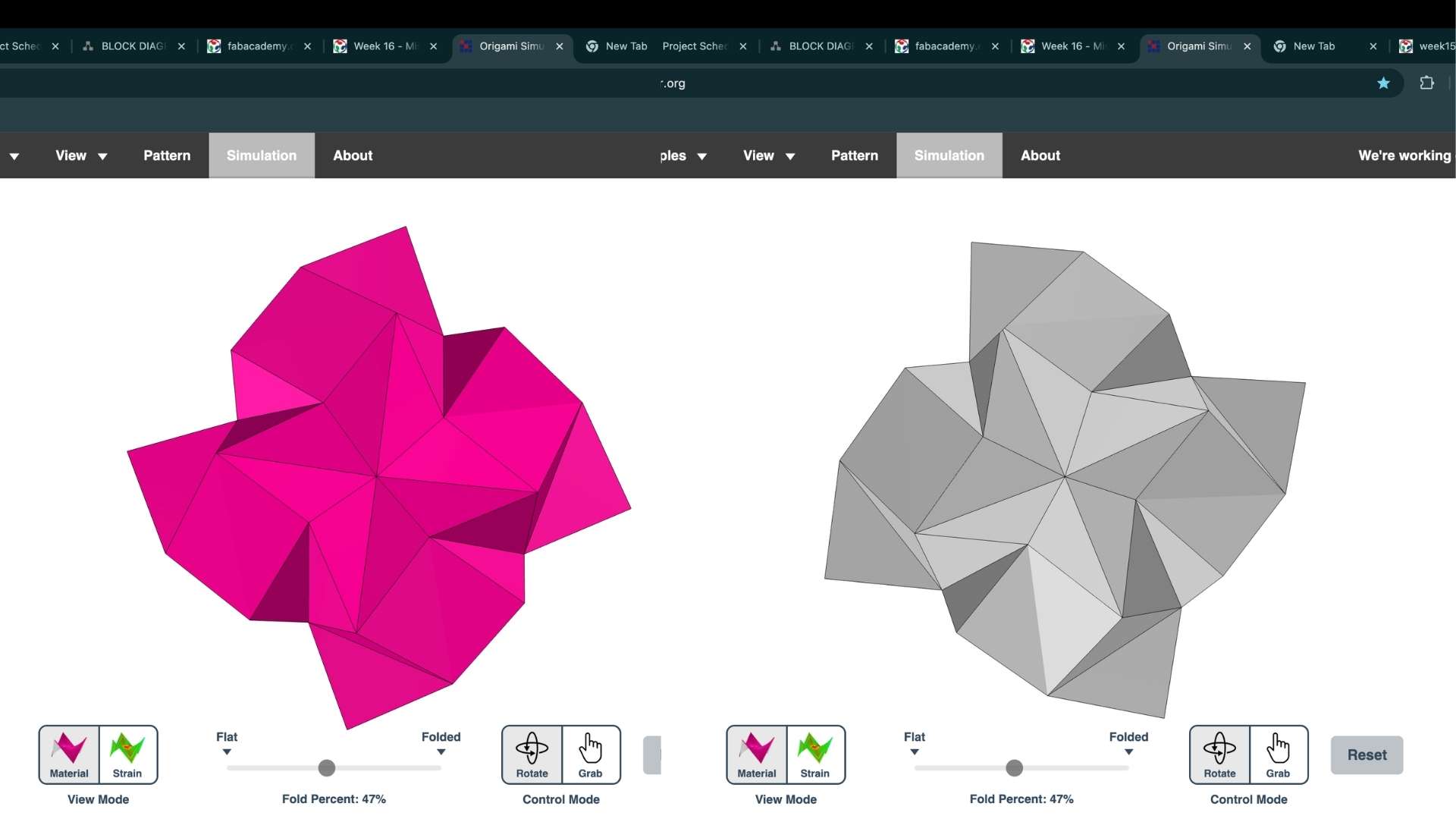
Origami Simulator is a browser-based application developed by Amanda Ghassaei for visualizing how origami crease patterns fold into three-dimensional forms. By assigning mountain folds, valley folds, and boundary edges through color-coded lines, users can import their own crease patterns and simulate the resulting geometry. I used it to verify the folding behavior of my Waterbomb Tessellation before moving on to fabrication.
Paper helps you understand how the mountain and valley folds interact and how the tessellation collapses. Once the folding sequence makes sense in paper, translating the same crease pattern to metal becomes much easier.
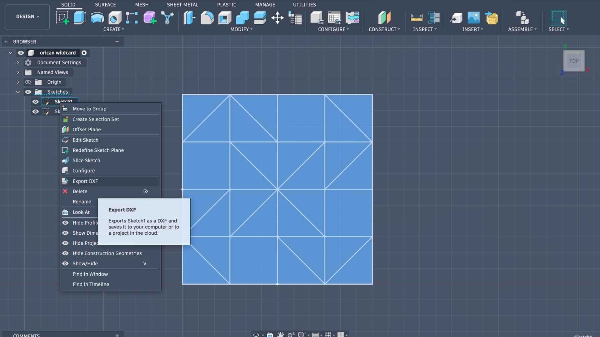
I did not recreate the crease pattern in Inkscape. Instead, I exported the completed sketch from Fusion as a DXF file and imported it into Inkscape. The purpose of this step was to assign different stroke colors to the crease lines so that the pattern could be interpreted correctly by Origami Simulator.
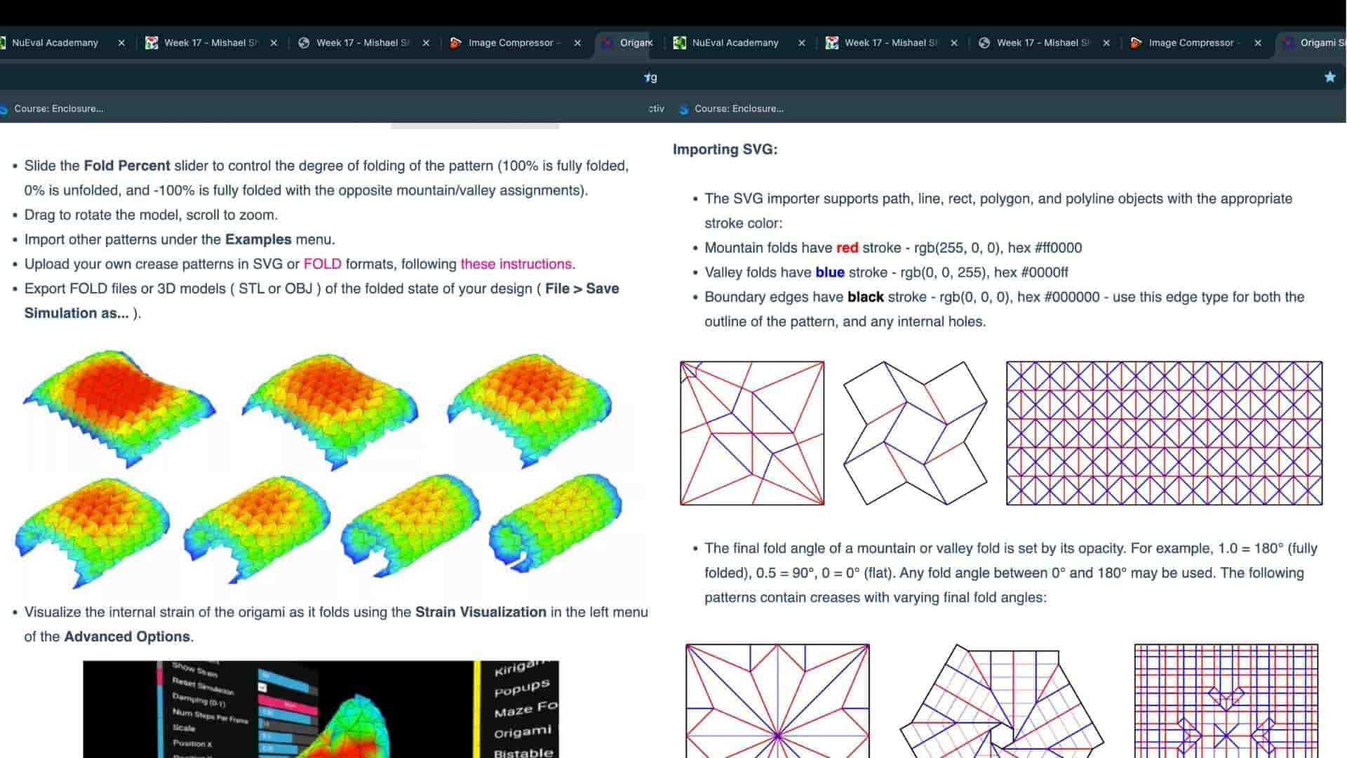
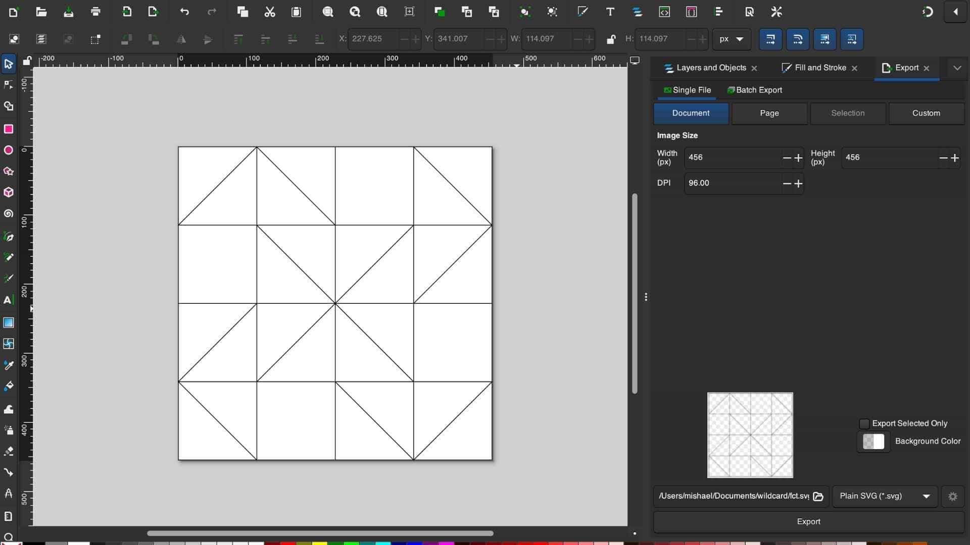
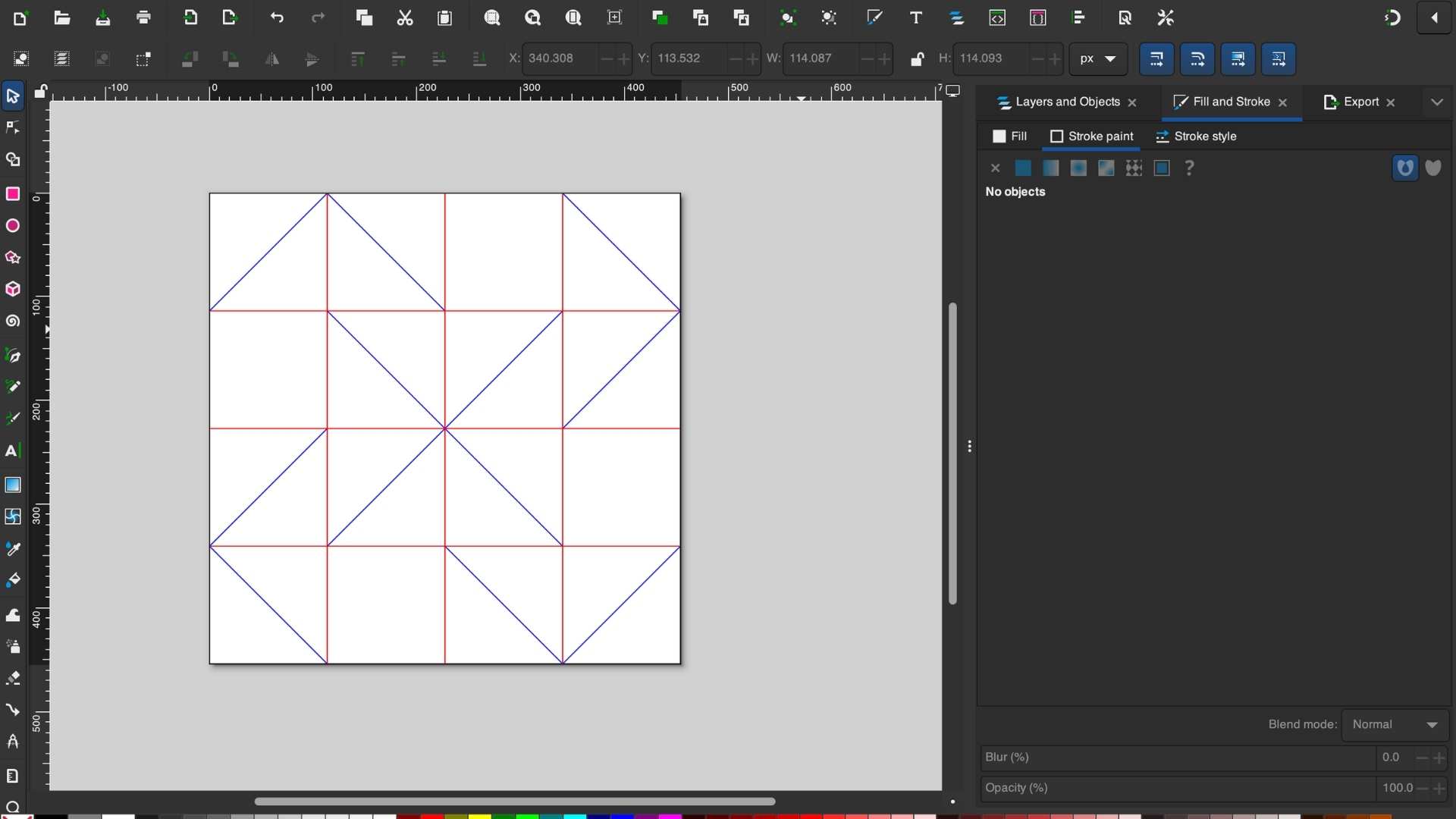
According to the origami simulator documentation, fold types are identified using line colors. I therefore color-coded the crease pattern as follows:
- Red for mountain folds
- Blue for valley folds
- Black for the outer boundary
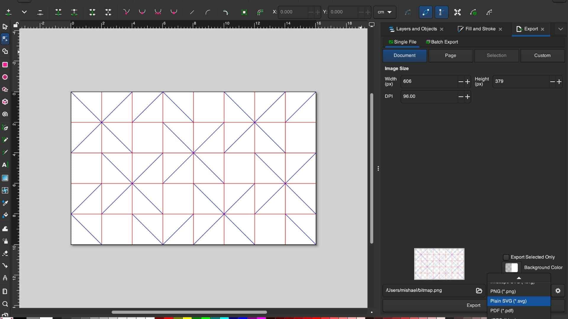
Since the Waterbomb Tessellation follows a consistent folding rule, assigning the colors was straightforward: all horizontal and vertical grid lines were designated as mountain folds, while all diagonal lines were designated as valley folds. Once the color coding was complete, the file was exported as an SVG and imported into Origami Simulator to verify that the crease pattern folded as expected before moving on to fabrication.
In Inkscape, I color-coded the lines to make the crease logic easier to read for the simulator:
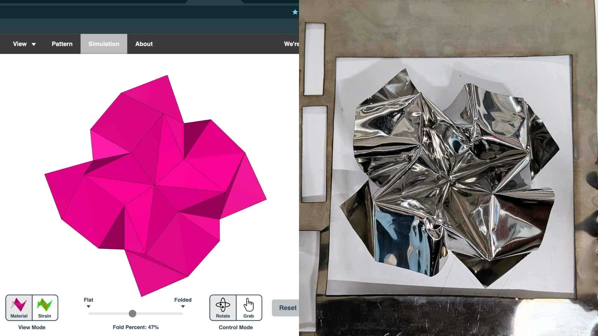
This file was then imported into Origami Simulator to verify that the crease pattern folded as intended before committing to fabrication.
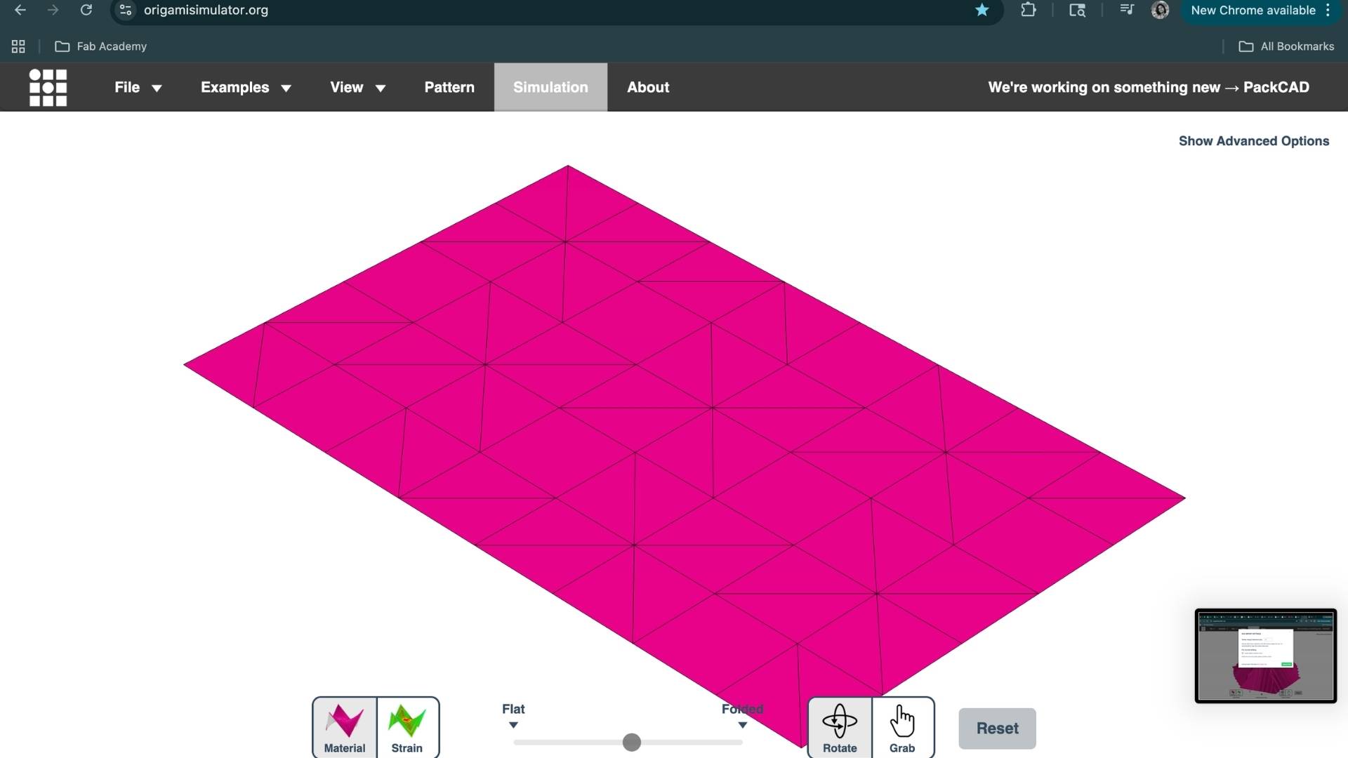
The simulation confirmed that the pattern behaved as expected.
First Attempt: Flattened Aluminum Can Sheet
Although I used a pre-flattened aluminum sheet available in the lab for this test, anyone wishing to replicate the process from scratch can prepare their own sheet from a beverage can. The following video demonstrates one method for flattening and preparing the material for fabrication.
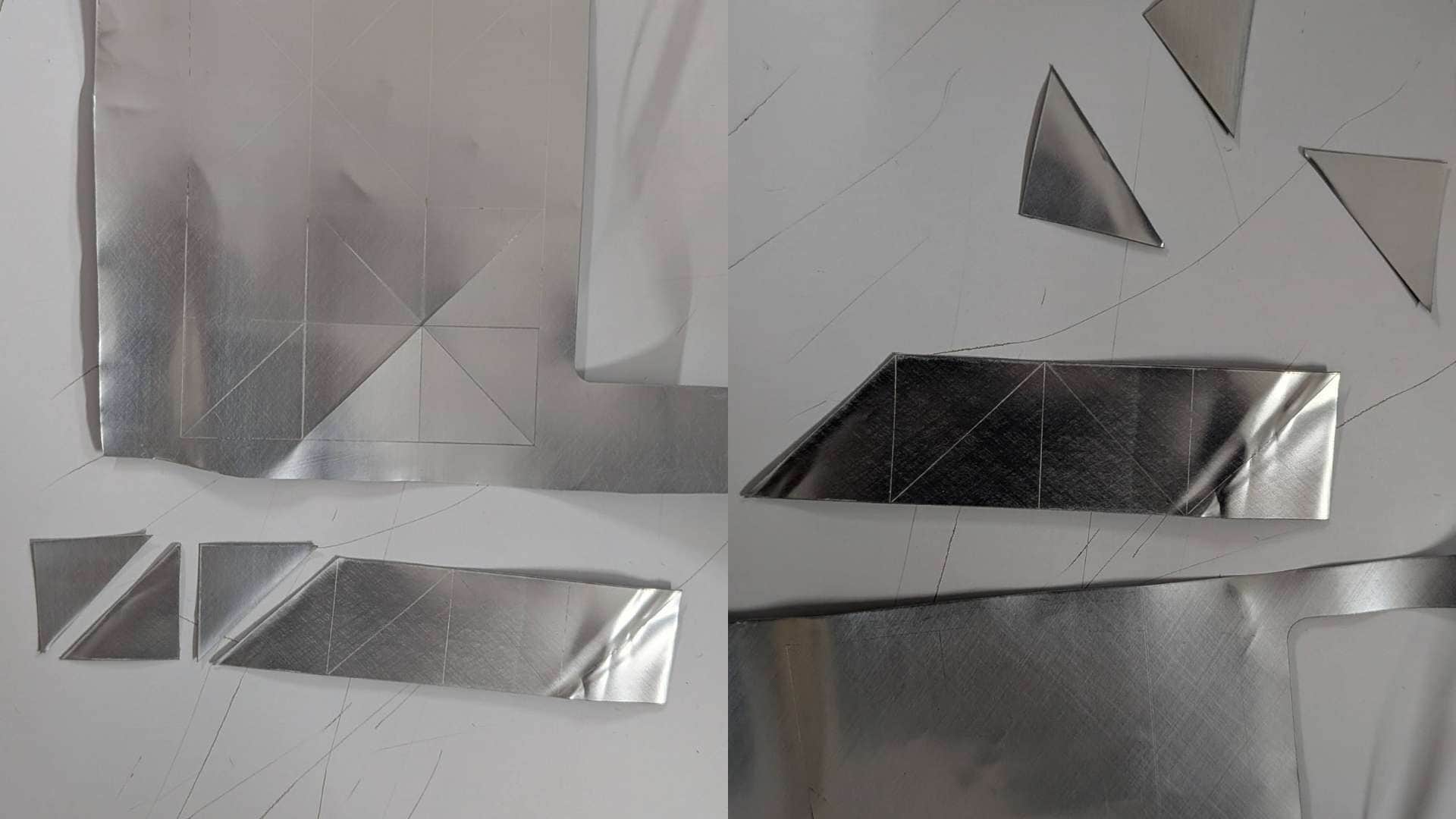
My first prototype used a flattened aluminum beverage can. The material was easy to source and thin enough to fold by hand, so it seemed like a good starting point.
I laser cut and scored the crease pattern using the xTool F1 Ultra.
However, the experiment failed almost immediately.
Even without deep scoring, the aluminum tore along the fold lines. Beverage cans are made from extremely thin, work-hardened aluminum, and once bent, the material tends to crack rather than form crisp creases. The folds had very little structural integrity and the sheet quickly separated at the crease lines.
It was a useful failure, but a failure nonetheless.
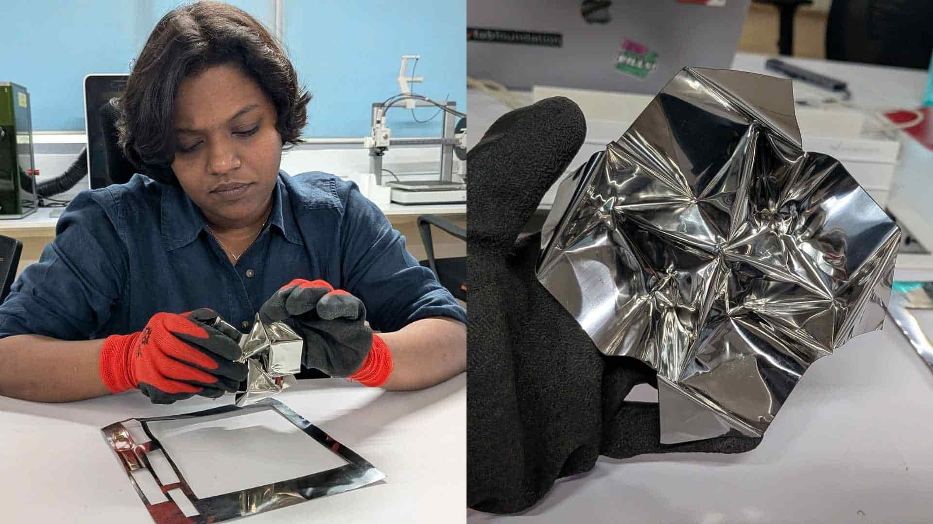
Switching to Stainless Steel
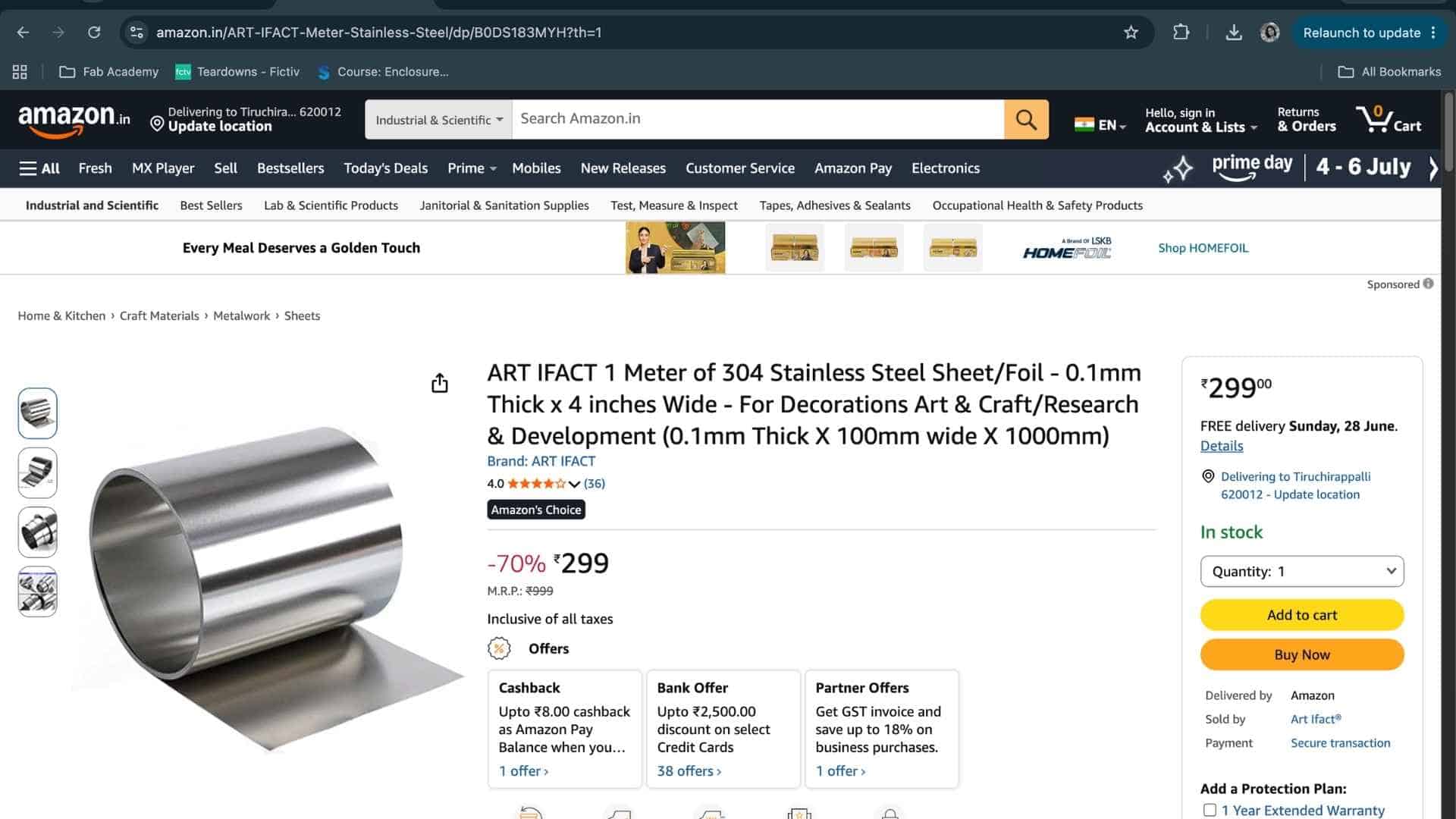
After discussing the issue with Saheen, we decided to try a thin piece of 304 stainless steel sheet that was available in the lab.
Compared to the can aluminum, the stainless steel was far more robust and could tolerate repeated scoring and folding without tearing.
Safety Considerations
Working with metal origami introduced a different set of safety considerations compared to paper. During laser processing, the xTool F1 Ultra was operated with proper ventilation and with all safety features enabled. The machine remained closed and supervised throughout the scoring process.
The bigger concern came after fabrication. The laser-cut metal edges were surprisingly sharp and required careful handling during folding. Gloves were used whenever significant force was applied, and the piece was only held directly by hand for brief documentation photographs. Unlike paper, this version had no hesitation in reminding me when I got too comfortable.
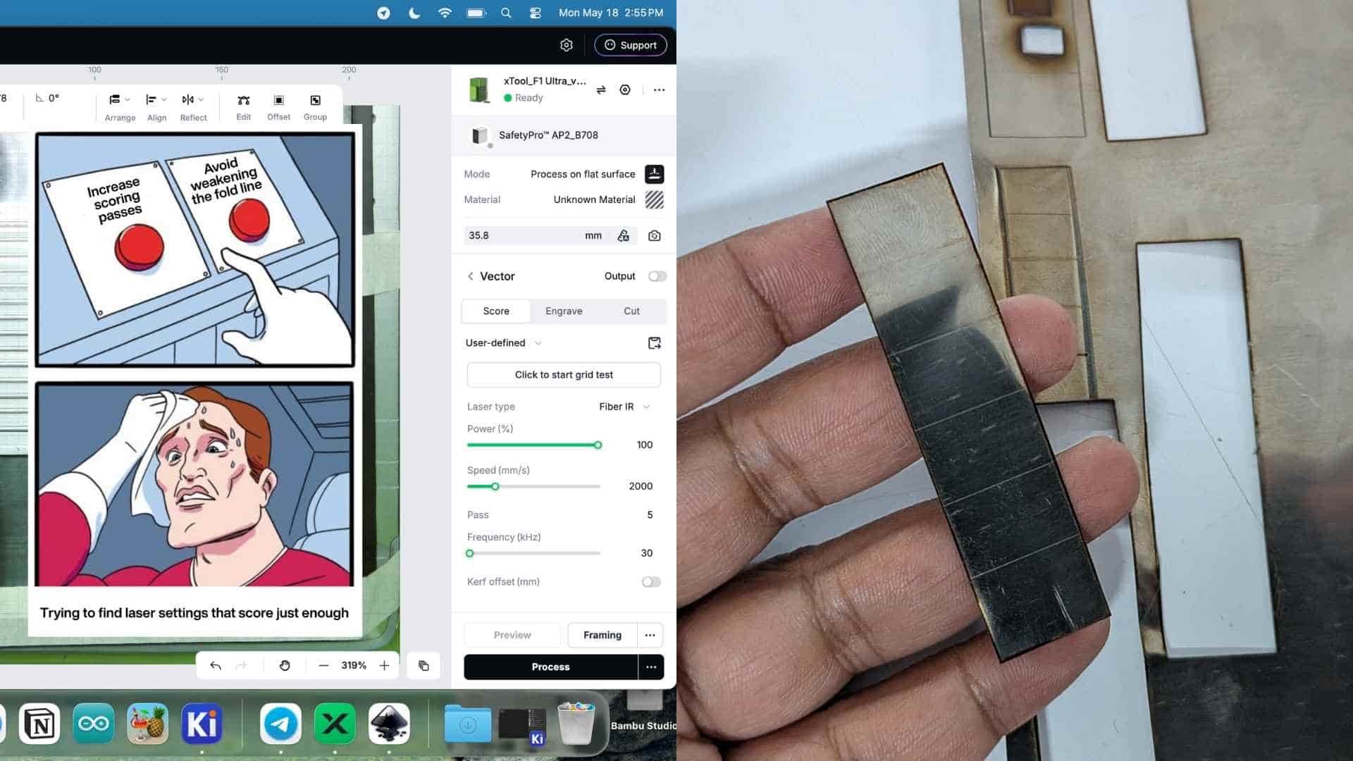
Parameter Testing
Before committing to the full pattern, we ran a series of small test strips to determine suitable parameters for both scoring and cutting. The primary variables were speed and number of passes.
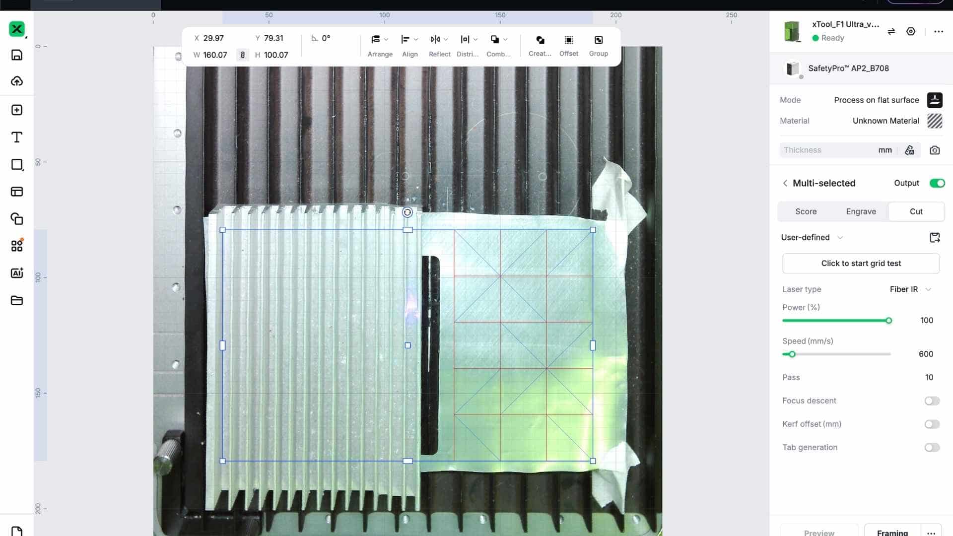
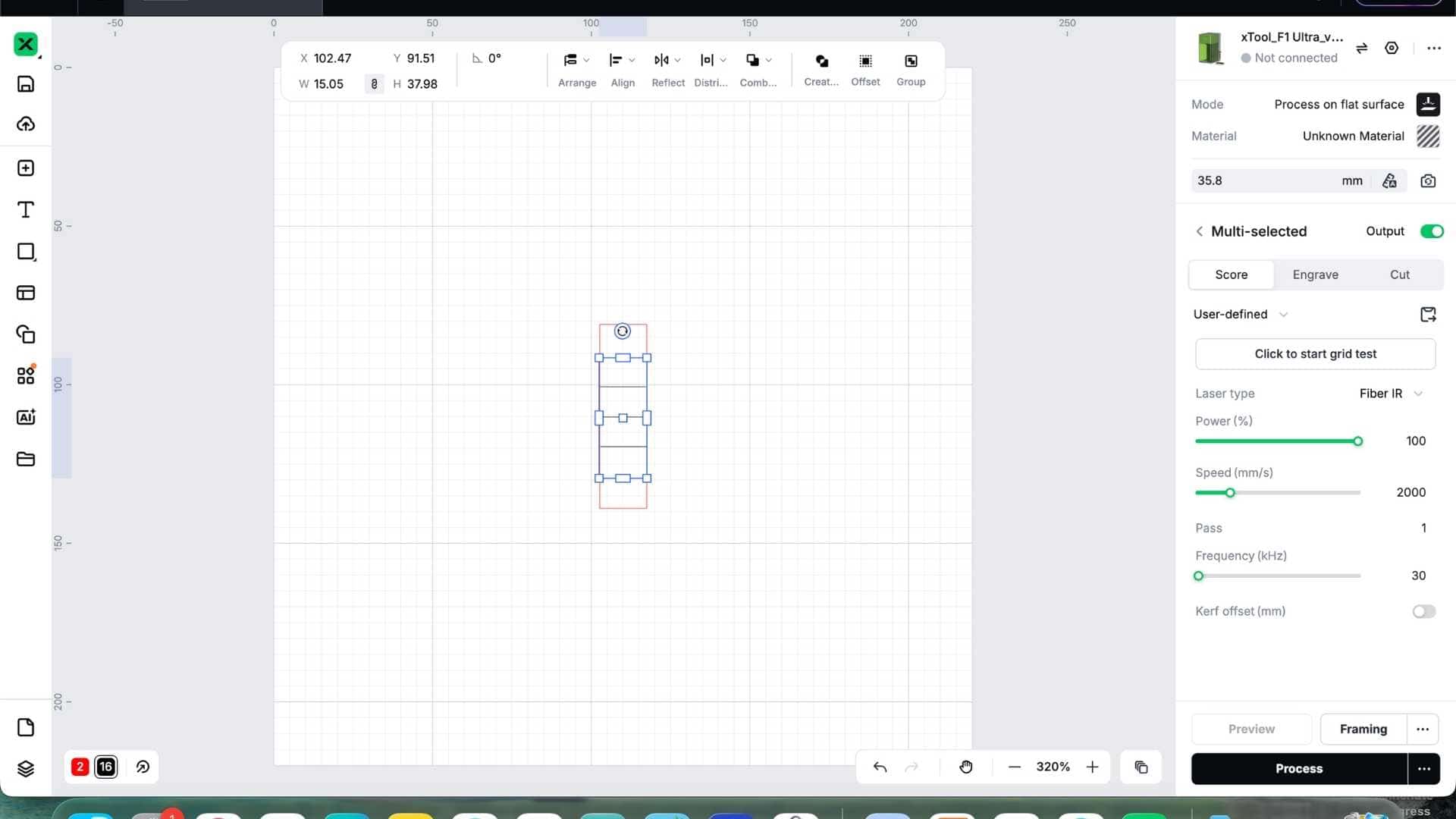
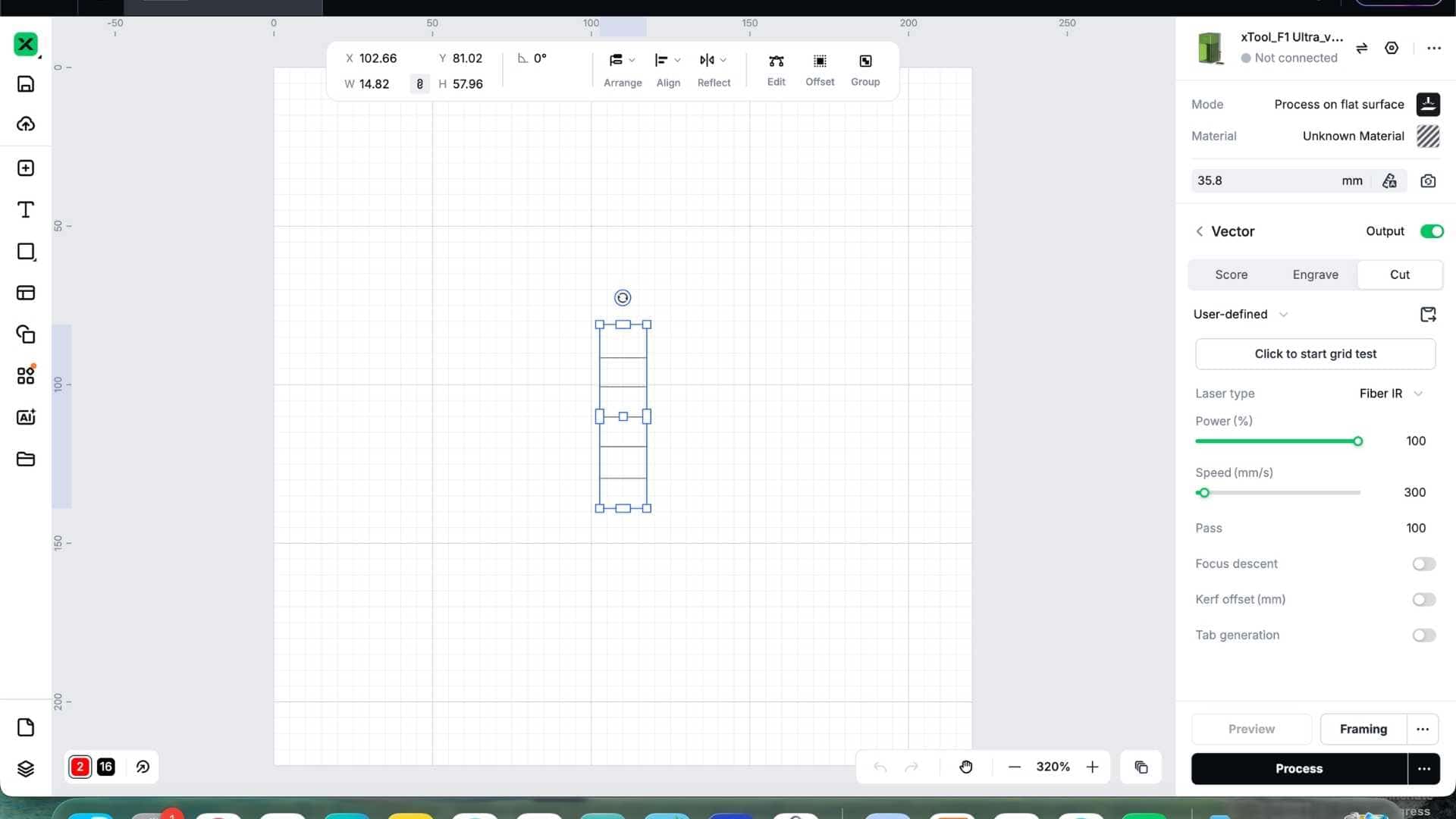
Separating Score and Cut Operations in xTool Creative Space
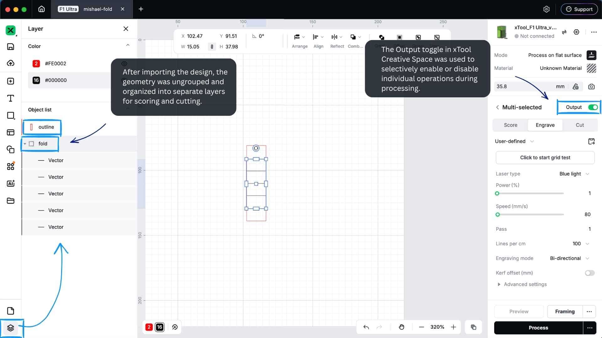
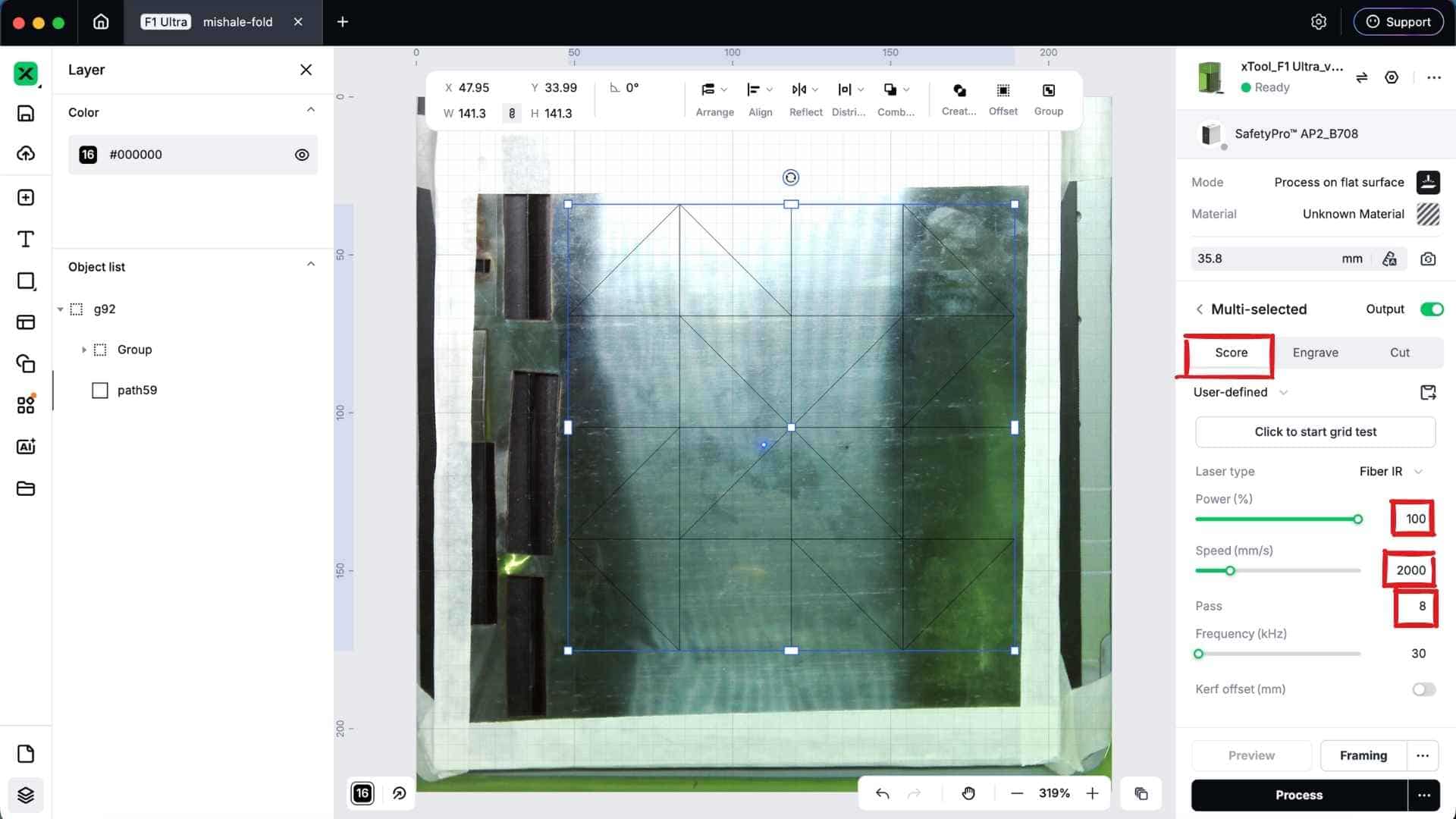
After importing the design into xTool Creative Space, both the cut boundary and fold lines were initially treated as part of the same design. To assign different operations, I first opened the Layers panel by clicking the layer icon at the bottom-left corner of the workspace.
The imported geometry was then ungrouped, allowing the fold lines and outer cut boundary to be selected independently. Once separated, the fold lines were grouped into one layer and the outer boundary into another.
This made it possible to assign different laser operations to each group:
- Fold lines → Score operation
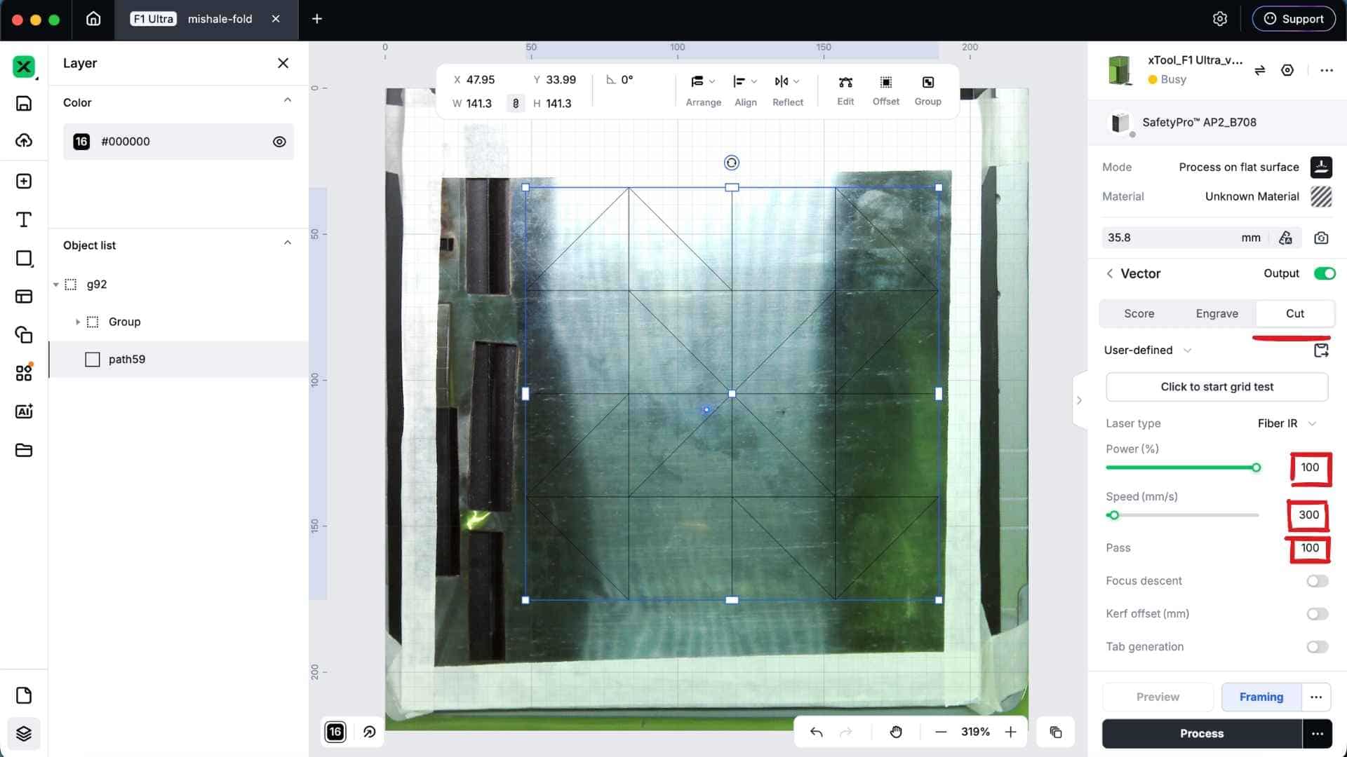
- Outer boundary → Cut operation
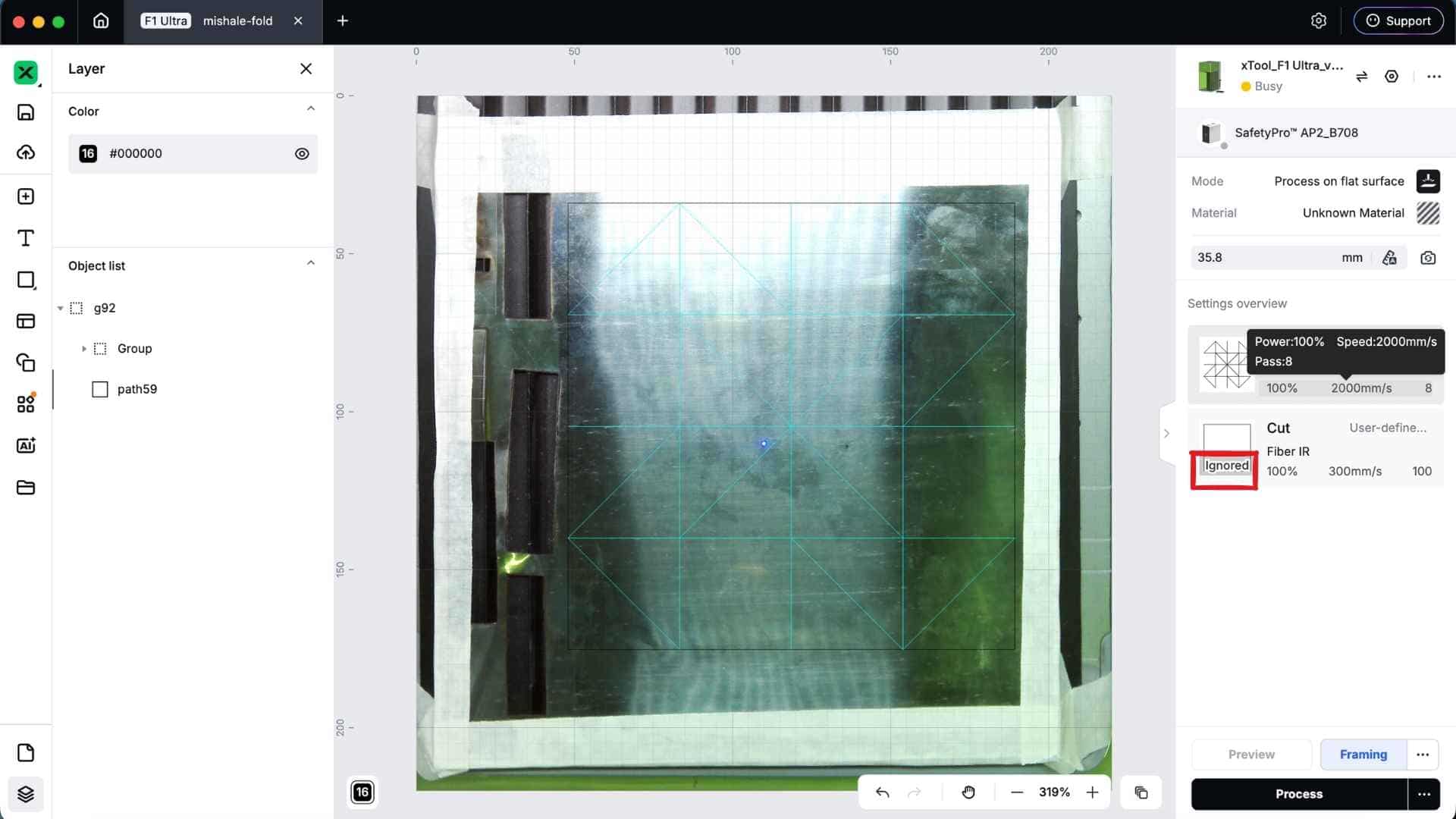
When preparing the job, xTool Creative Space provides an Output toggle for each layer in the process panel. This allows individual operations to be enabled or disabled as needed. For example, I could run the scoring pass while temporarily disabling the cut layer, then enable the cut layer for a separate pass. Any layer with Output turned off is ignored during processing.
After several iterations, we settled on the following settings:
Scoring Parameters
Cutting Parameters
These settings produced clear score lines and clean perimeter cuts while preserving enough material strength at the fold lines.
Revising the Pattern
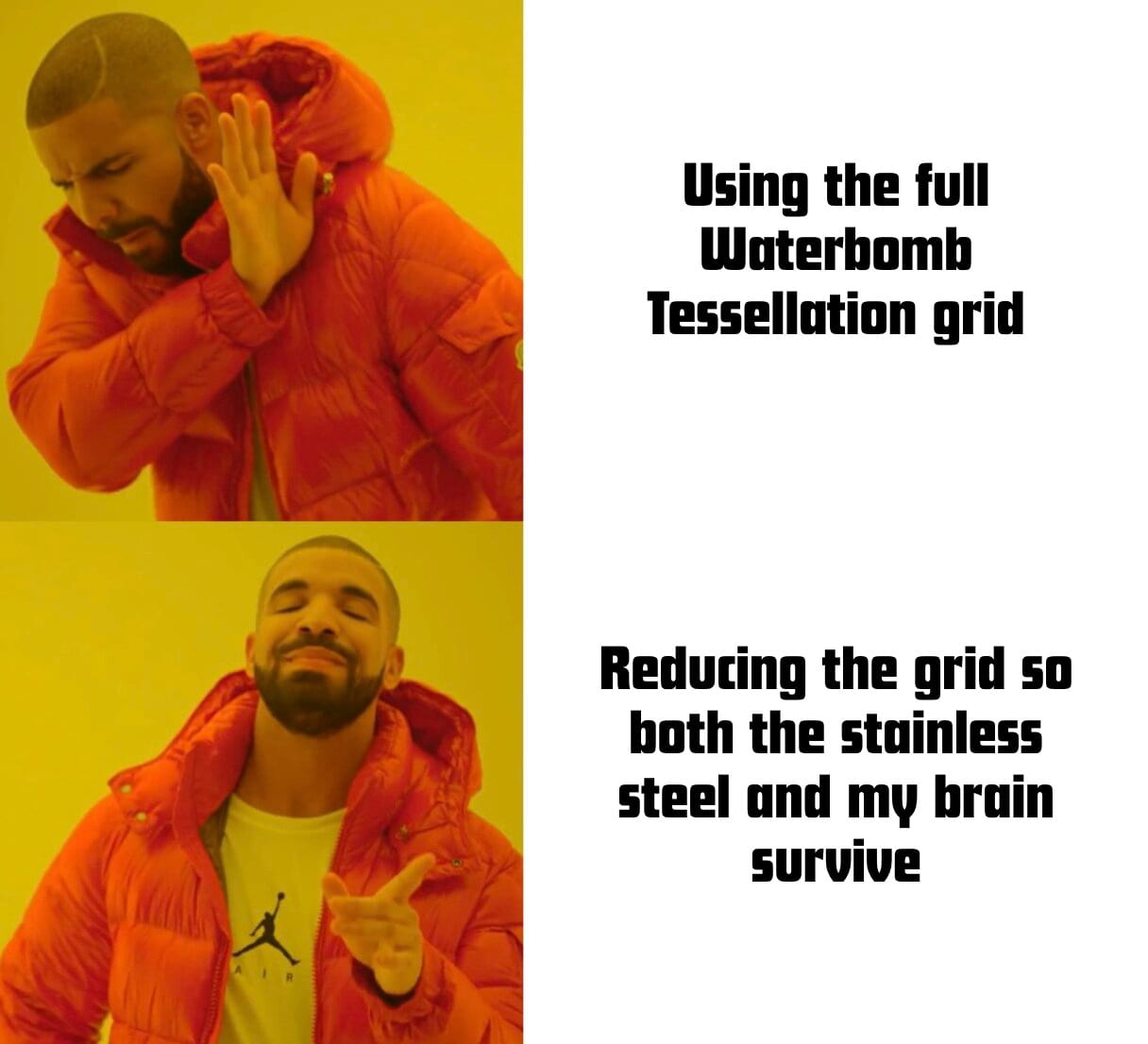
Since stainless steel is significantly stiffer than paper, I simplified the design and reduced the number of grid cells to make the pattern more manageable to fold by hand.
The revised crease pattern retained the essence of the Waterbomb Tessellation while keeping the folding process within reasonable limits.
Repeated the process: export as dxf >> colour code for simulation and export as svg >> simulate on origami simulator >> open on xTool
Red for Mountain folds
Blue for Valley folds
Black for Outlines
Laser Processing on F1 Ultra
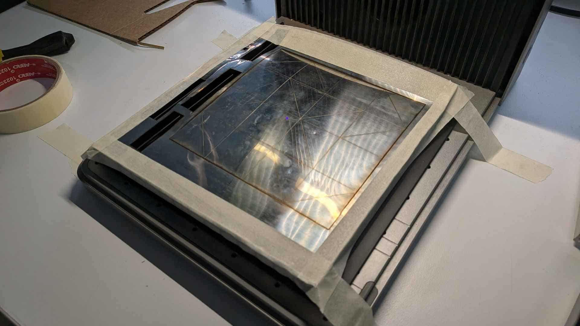
The stainless steel sheet was secured carefully to the bed to prevent movement during processing.
The fabrication sequence was:
Scoring first ensured that the sheet remained dimensionally stable during marking and avoided alignment issues.
Make sure to toggle off output for the operation that is not being performed. This will ignore that operation.
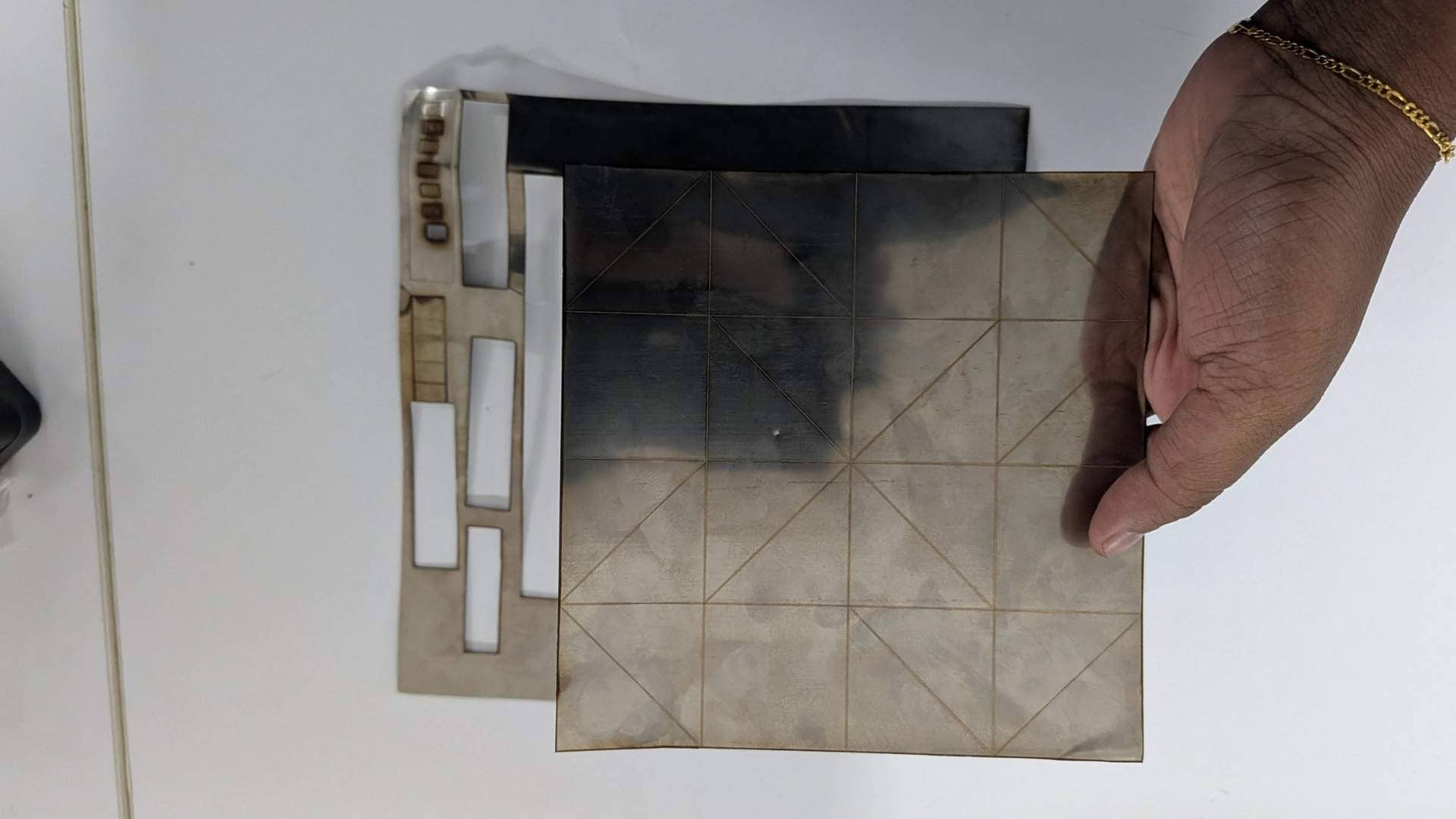
Scoring
Cutting
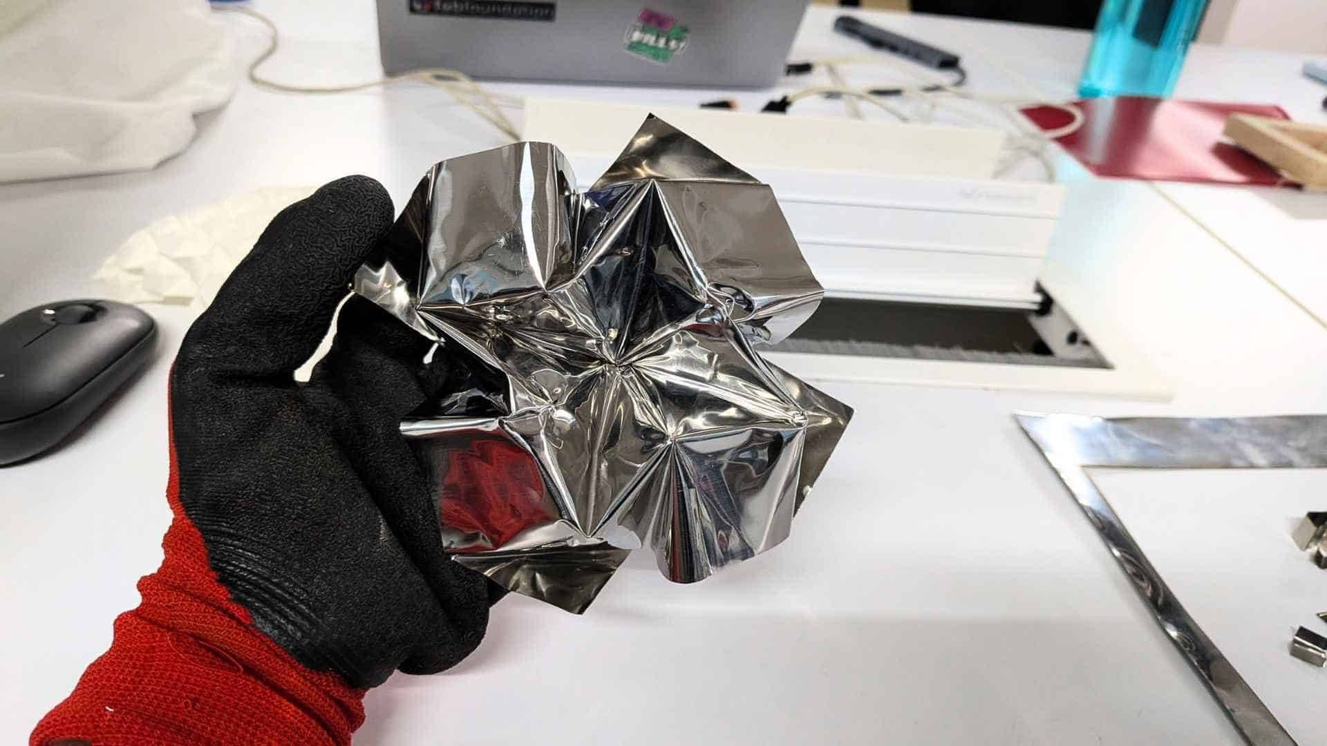
Folding the Metal

Folding the stainless steel required considerably more force than folding paper. Each crease had to be worked gradually by hand,and steady pressure to encourage the sheet into shape.
It was definitely the most physically demanding part of the process yet most satisfying.
Despite the resistance of the material, the scored crease lines guided the folds, and the final geometry closely matched the digital simulation.
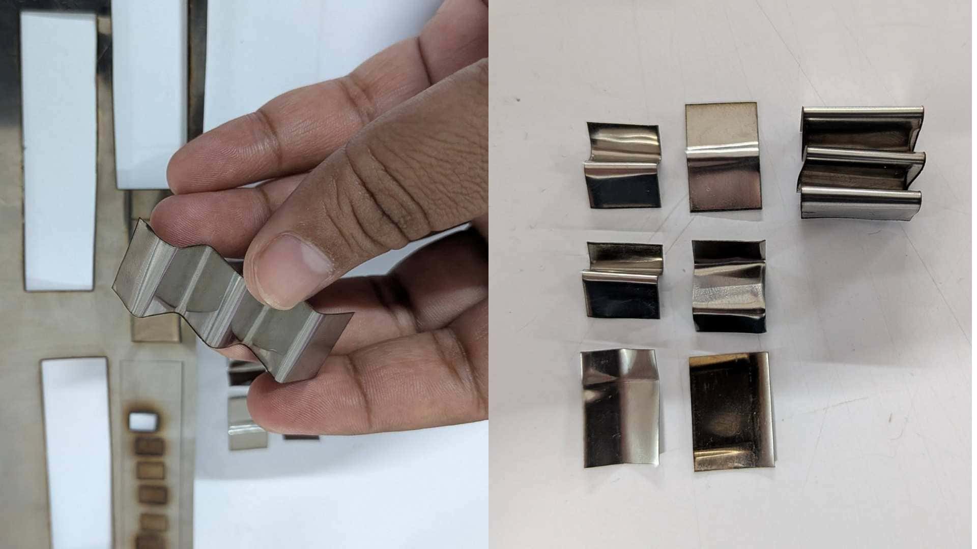
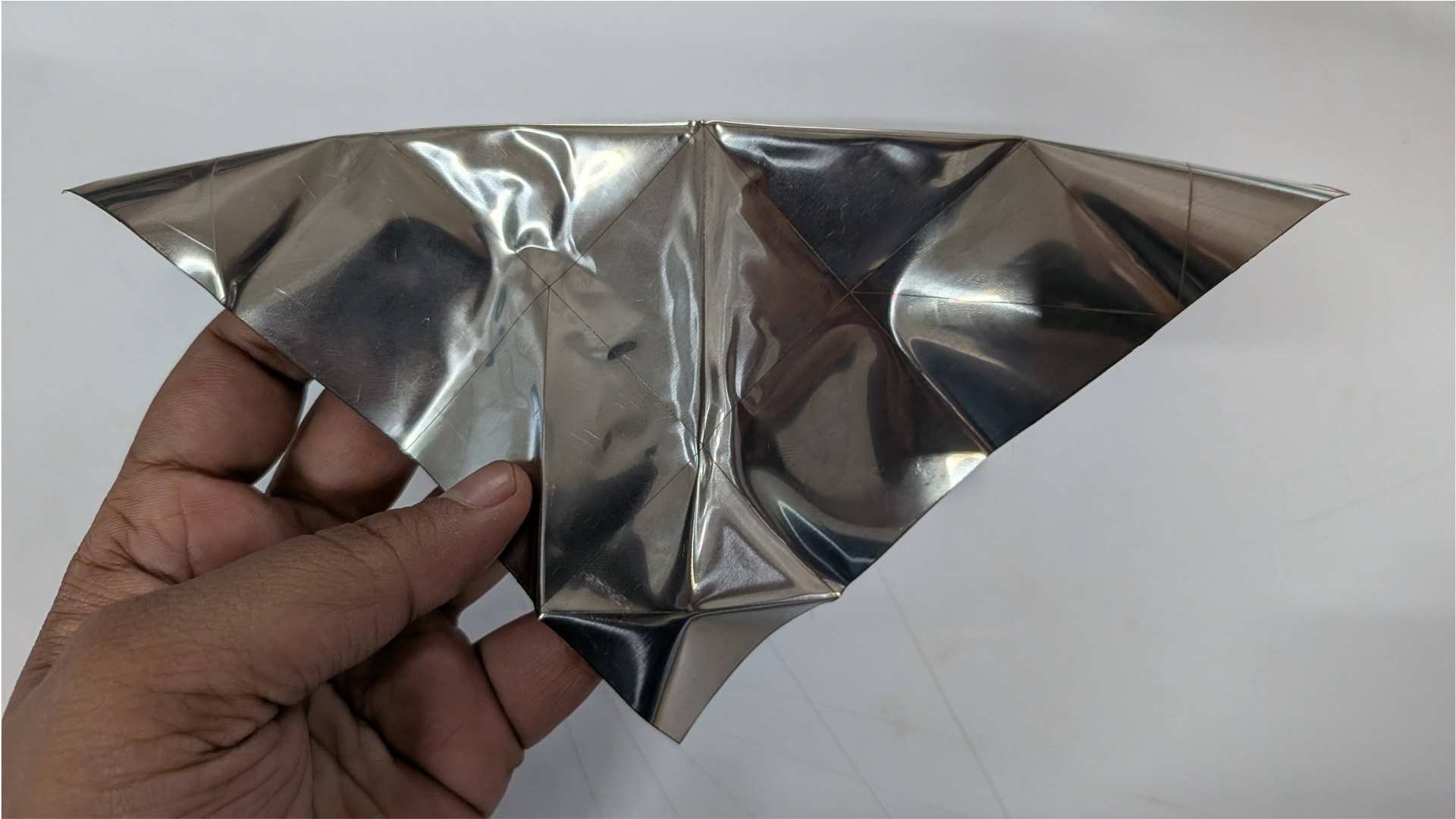
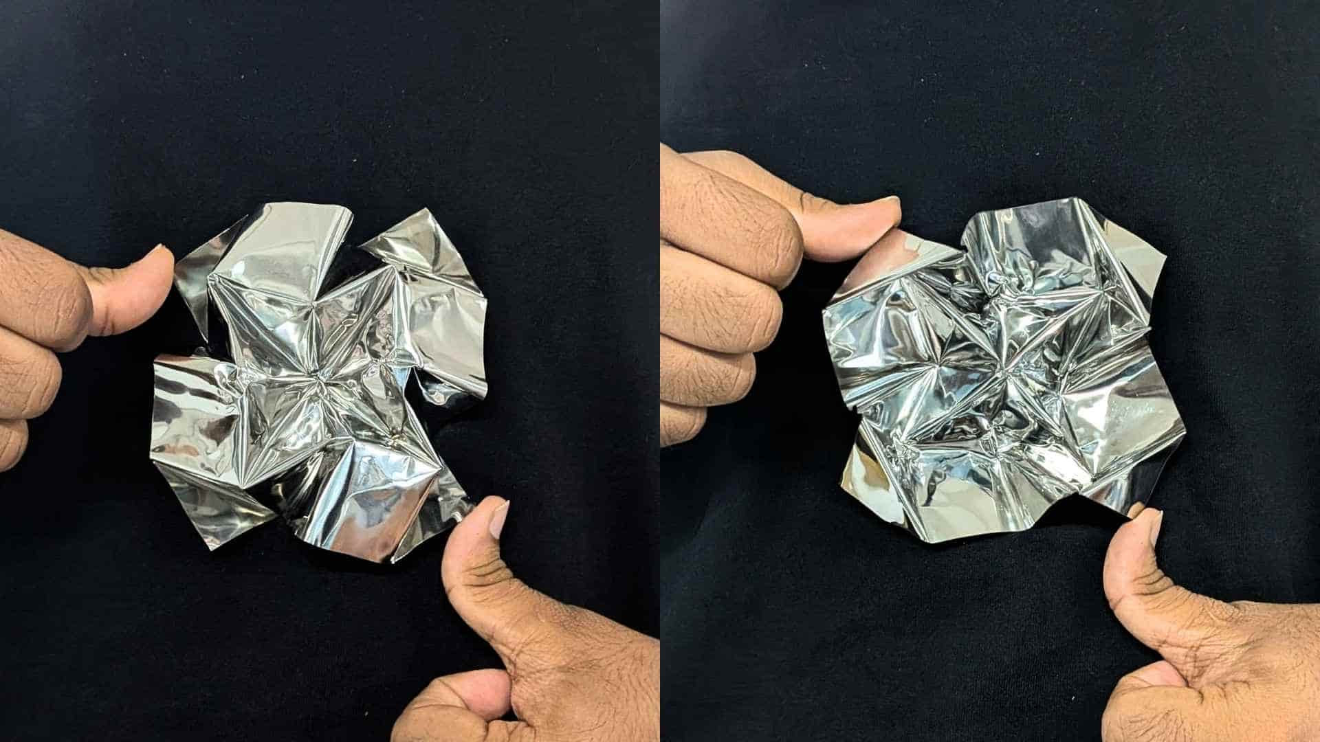
Hero Shot
Challenges Observed in the Final Folded Piece
Although I was determined to see the piece fully folded, the final result revealed several limitations of working with stainless steel.
The outermost valley folds were comparatively easier to form because they were free and not constrained by surrounding grids. As the folding progressed toward the center, however, the process became significantly more difficult. Many folds had to be partially folded, unfolded, and refolded in sequence to allow the pattern to collapse correctly. With a rigid material like stainless steel, this repeated manipulation required considerable force and quickly became challenging.
The most critical issue occurred at the center of the pattern, where two diagonal creases intersected with one horizontal and one vertical crease. This concentration of multiple fold lines created a stress point, and although the model could still be folded, the material eventually cracked at that junction. Interestingly, a similar effect can sometimes be observed in paper when too many creases converge at a single point, but I was not expecting the stainless steel to tear in the same way.
The valley folds located between adjacent grids were the most difficult to execute. Once folded, the material was not forgiving, and reopening or adjusting these folds was extremely hard. Unlike paper, which tolerates small corrections, stainless steel tends to retain deformation and resists being reshaped.
Since this sheet was a leftover piece found in the lab, I do not know its exact grade or thickness. However, based on this experience, I would choose a thinner sheet for future experiments to allow greater control and reduce the force required during folding. Unfortunately, this was the only piece available, so material selection was limited to what was on hand.
Despite these issues, the piece successfully demonstrated that laser-scored stainless steel can be folded into complex origami forms, while also highlighting the structural and practical constraints of working with rigid sheet metal.
In many ways, the cracks and resistance were as informative as the successful folds, because they revealed where the geometry and the material were pushing against each other.
Insights
As someone who has been folding for quite some time, I was curious to see how origami would behave in a completely different material. This week introduced me to rigid folding, which felt very different from the paper-based folding I am used to.
My first attempt with a flattened aluminum can sheet failed completely. The material tore along the crease lines and could not hold the folds. Switching to stainless steel was much more promising, although the material was significantly more rigid and required considerably more force and patience to fold.
A large part of this week was spent testing laser parameters to understand what worked and what did not. Through several iterations, I learned that cutting required lower speed and a high number of passes, while scoring worked better at higher speed and fewer passes. If the scoring was done too slowly, too much material was removed, weakening the crease and causing it to break during folding. I also tested different combinations of speed and pass counts to find the settings that provided the best balance between guided folding and material integrity.
I also made a conscious decision to reduce the number of grid cells from the original Waterbomb Tessellation. Stainless steel does not behave like paper, and attempting the full crease pattern would have made the folding process unnecessarily difficult. Simplifying the pattern was definitely the right call, it made the piece much more manageable and allowed me to focus on understanding the material rather than fighting with it.
Even with thick paper, material resistance becomes noticeable as the thickness increases. With stainless steel, that resistance was amplified. That said, years of folding experience definitely helped. Once the sheet was scored, my hands instinctively started reading the crease pattern and building the form.
I was unsure at first whether the stainless steel would fold as intended, but halfway through, determination took over and I was excited to see the final result emerge. My fingers were sore by the end, but it was well worth the effort.
This experiment reminded me that every material and fabrication process comes with its own possibilities and limitations. The key is to understand those constraints while continuing to explore what is possible.
I would love to continue experimenting with metal origami in the future, using different sheet materials, thicknesses, and fabrication techniques.