Week 5: 3D Scanning and Printing
This week’s assignments are divided into group and individual work. As a group, we will test the design rules and limitations of our 3D printers to understand their capabilities and constraints. Individually, I will design, document, and 3D print a small object (a few cubic centimeters) that cannot be made using subtractive manufacturing methods. I will also 3D scan an object and optionally explore printing the scanned model.
Jogin, Mufeed, and Saheen guided us this week.
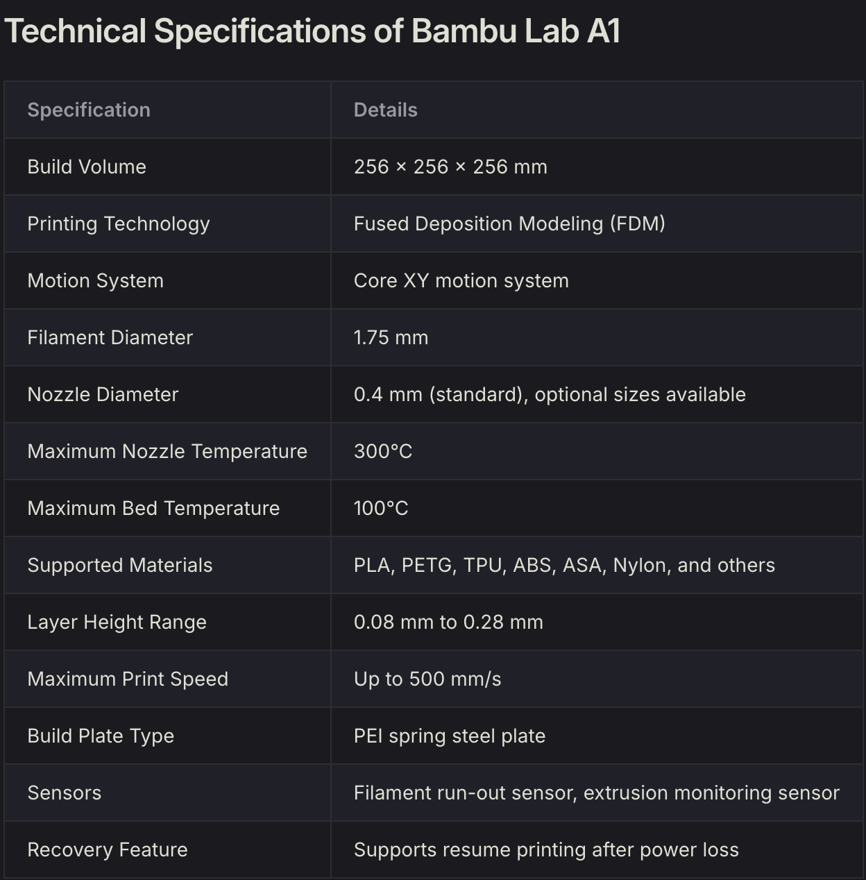
Group Assignment: Bambu Lab A1 Characterization and PLA Material Study
Through the Group Assignment, we characterized the Bambu Lab A1 FDM 3D printer using generic PLA and a multi-feature calibration model to understand its capabilities, limitations, and design requirements.
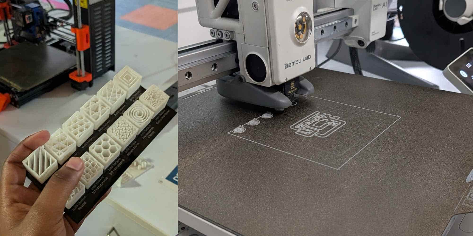
Printer Features and Build Surface
Features such as automatic Z-offset calibration, flow calibration, and vibration compensation improved print reliability and surface consistency by ensuring correct nozzle distance and stable extrusion. We used generic PLA, which printed easily with:
This made it suitable for prototyping and print-in-place mechanisms. The PEI spring steel plate provided strong adhesion when clean and allowed easy part removal after cooling, reducing the risk of print damage.
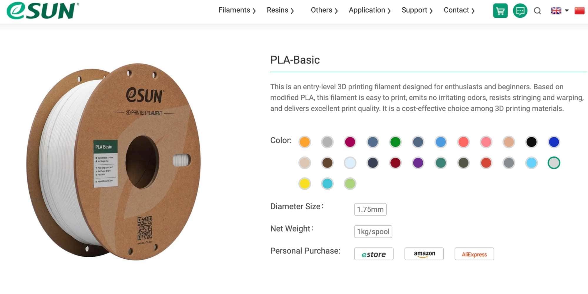
Filament Used: eSUN PLA-Basic
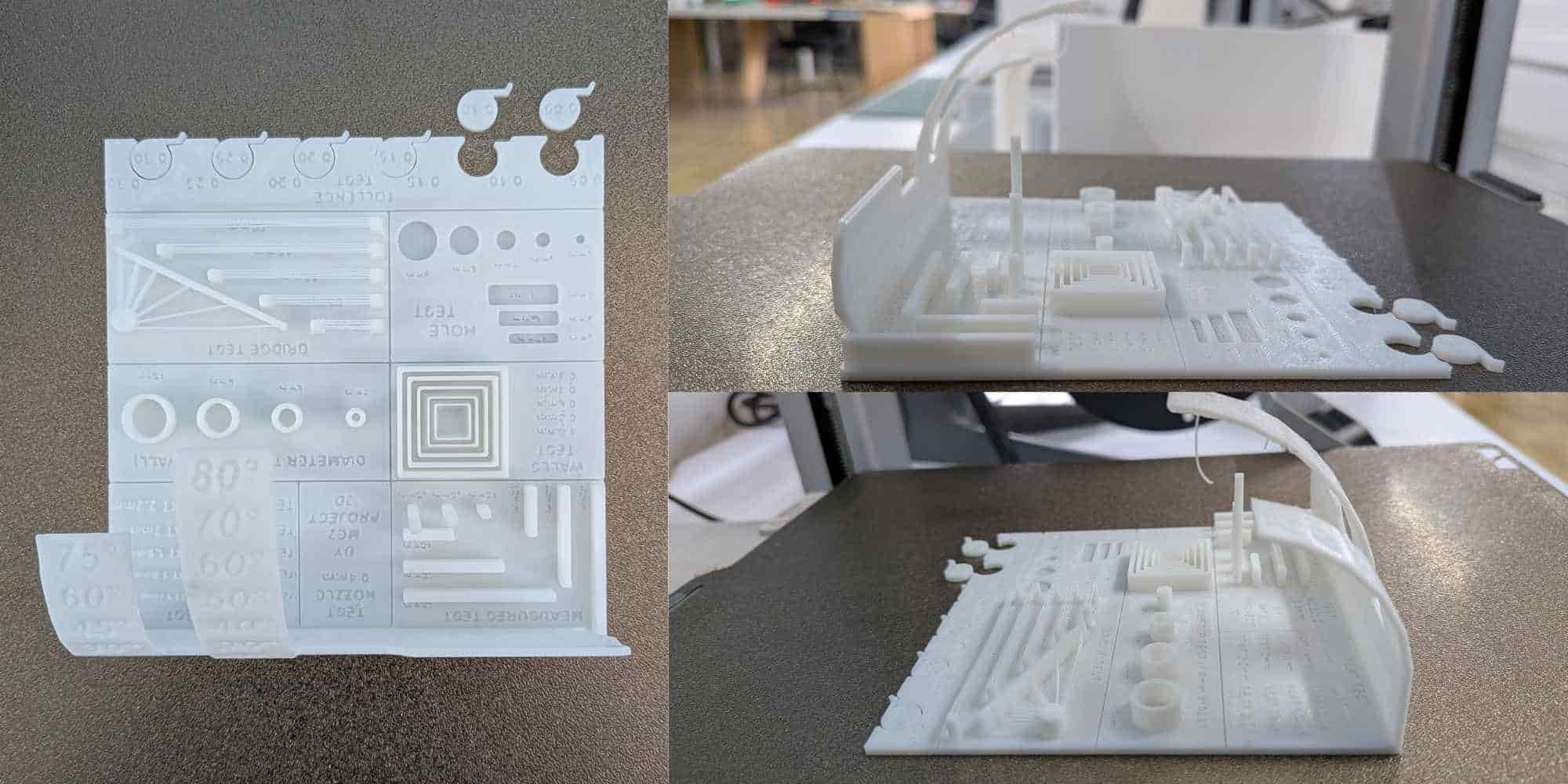
Dimensional Accuracy
Measurement tests showed good overall scaling accuracy across the X, Y, and Z axes. However: Holes and cylinders printed slightly undersized (≈0.25–0.40 mm) This occurs due to extrusion width and nozzle diameter Designs requiring precise fits must include dimensional compensation in CAD.Overhang and Bridging Performance
- Overhangs printed cleanly up to ~45° without supports
- Beyond 45°, drooping and surface defects began to appear
- Reliable bridging up to ~20 mm
- Longer spans showed visible sagging
- Supports or design changes are required for longer bridges
Clearance and Tolerance (PLA on Bambu Lab A1)
Observed clearances:- 0.05–0.10 mm: fused or immovable
- 0.15 mm: movable with friction
- 0.20–0.25 mm: smooth free movement
- 0.30 mm: loose fit
This shows that ~0.20 mm clearance is optimal for print-in-place moving parts on this printer with PLA.
Wall Thickness and Nozzle Relation
The printer uses a 0.4 mm nozzle, so:
- Minimum reliable wall thickness: ≥ 0.5 mm
- Thinner walls may print weakly or inconsistently
Due to anisotropy, parts are weaker along the Z-axis, so print orientation must be considered when designing functional components.
Conclusion
This characterization established practical design guidelines for the Bambu Lab A1 using PLA. Understanding its dimensional accuracy, clearance limits, overhang capability, and material behavior allows more reliable design of functional and print-in-place parts while reducing print failures.
3D Printing a Print-In-Place Maker Coin (Fusion 360)
For this week’s assignment, we had to 3D print under the following conditions:
Individual assignment:
The key requirement here was “could not be made subtractively”.
I decided to model a Print in Place Maker Coin following a YouTube tutorial on Fusion 360, it includes an internal moving body with clearance, something that would be impossible to machine once assembled.
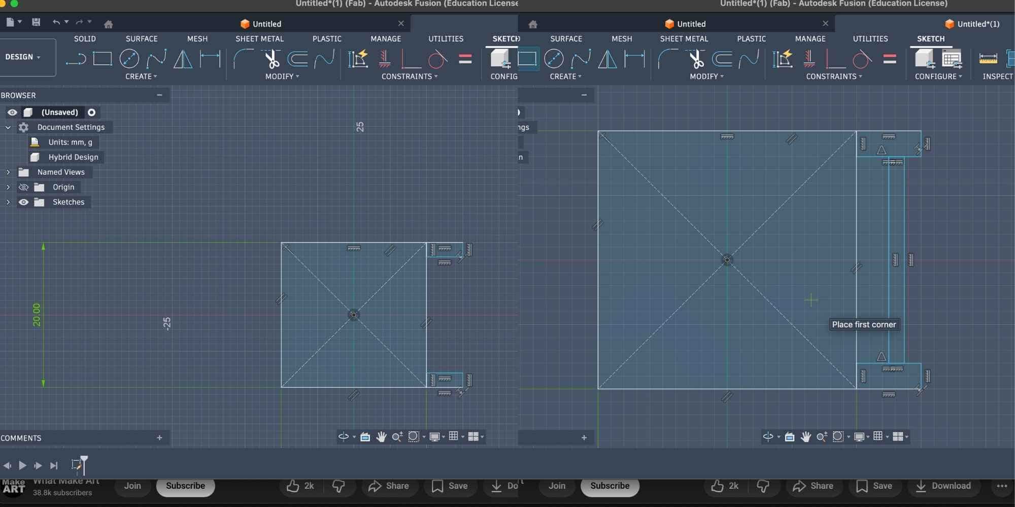
Modelling Process (Fusion 360)
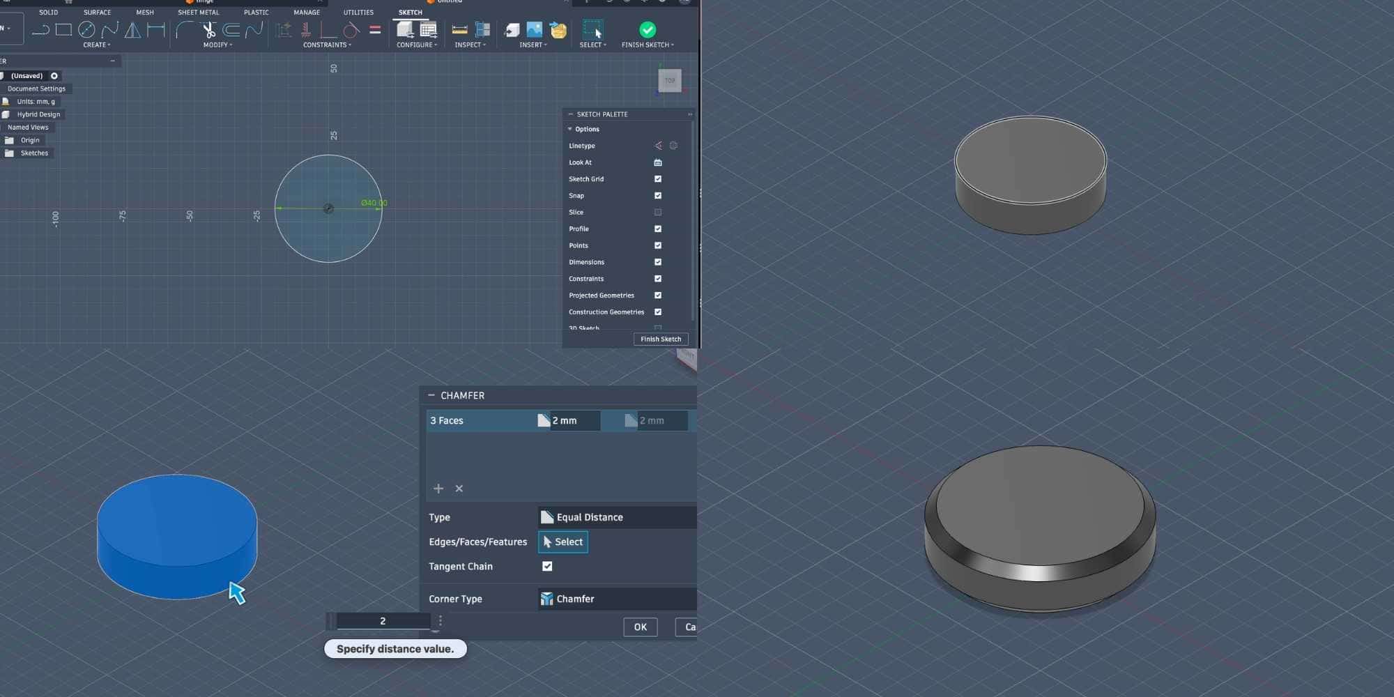
To begin, I created a sketch by drawing a circle of 40 mm diameter and extruded it to 10 mm thickness. The outer edges were chamfered to 2 mm to soften the profile and give it a coin-like appearance.
I then drew a smaller circle tangent to the inner circle and used
Create > Pattern > Circular Pattern
to replicate it. I selected the smaller circle and patterned it 24 times around the larger circle.
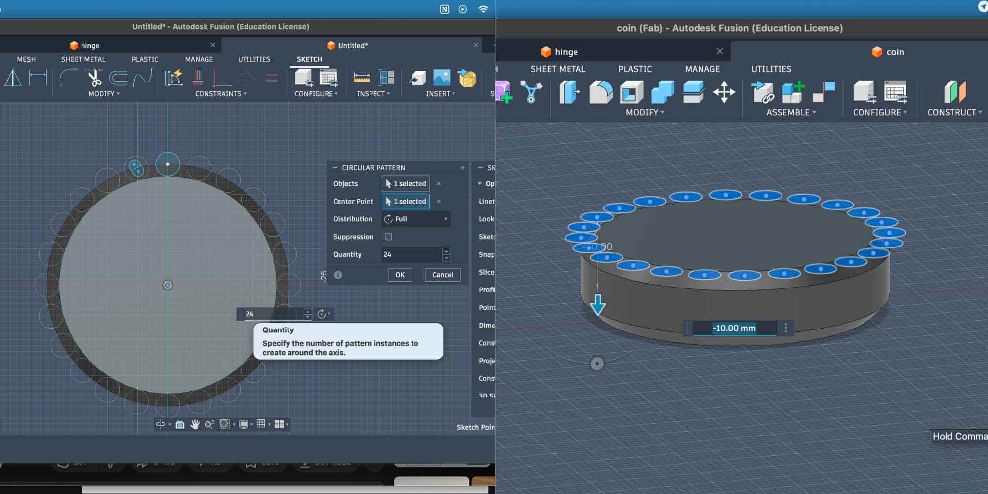
After finishing the sketch, I selected all 24 circles and extruded them to -10 mm using the Cut operation. This created a 3D patterned grip around the outer chamfered body.
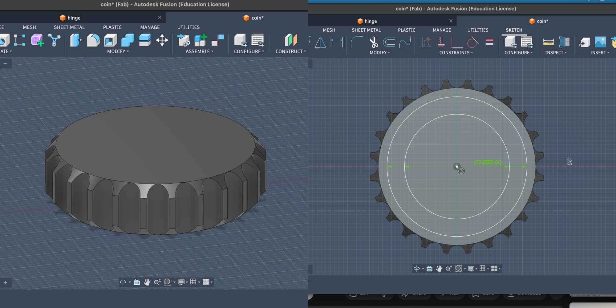
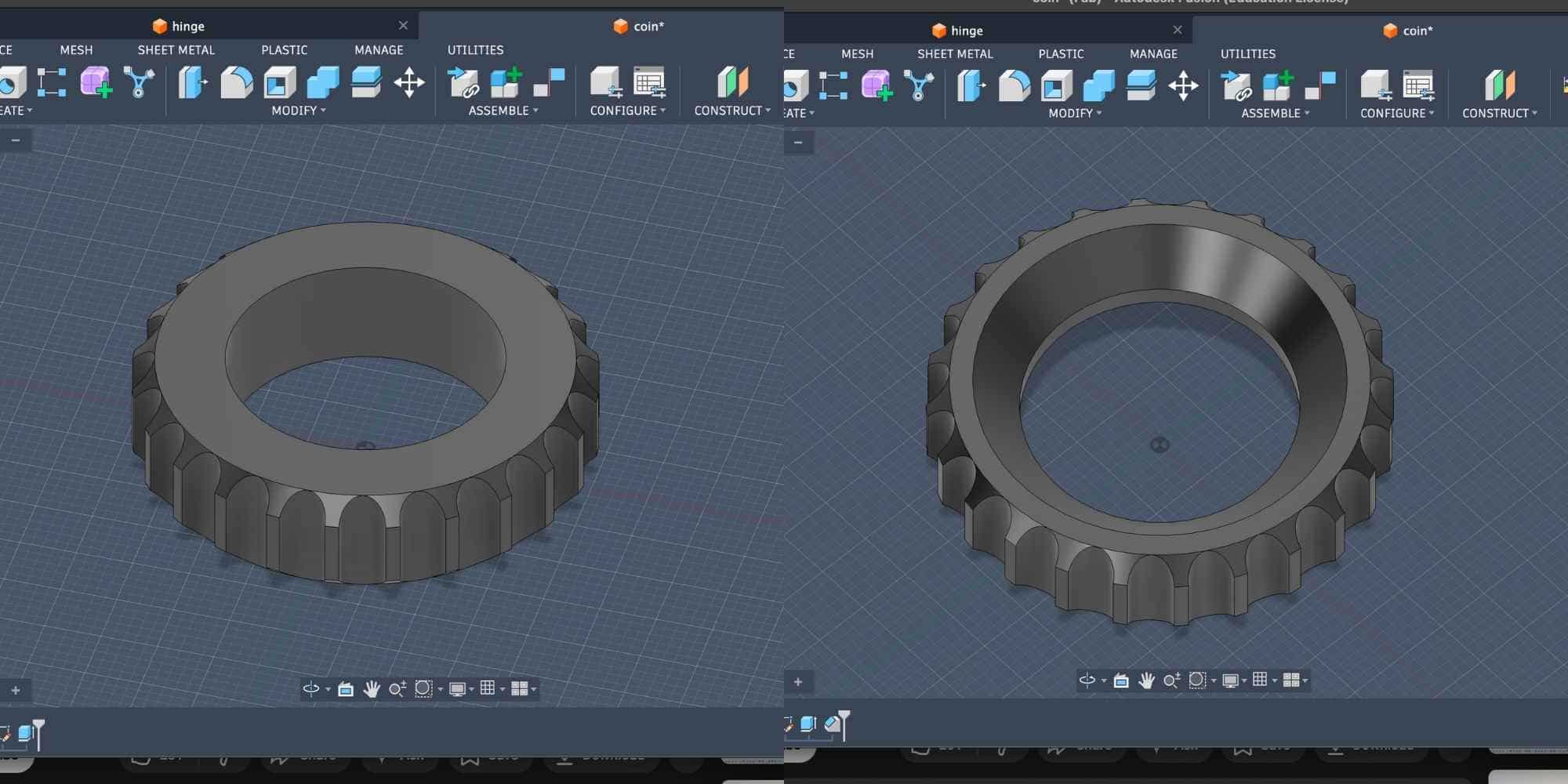
Next, I created two offset circles on the top surface of the main body. The smaller offset measured 24 mm in diameter. I extruded this circle all the way down using Cut, creating a hollow region in the center. Then I chamfered the outer edges of this inner circular cut.
Designing the Internal Body (Clearance Study)
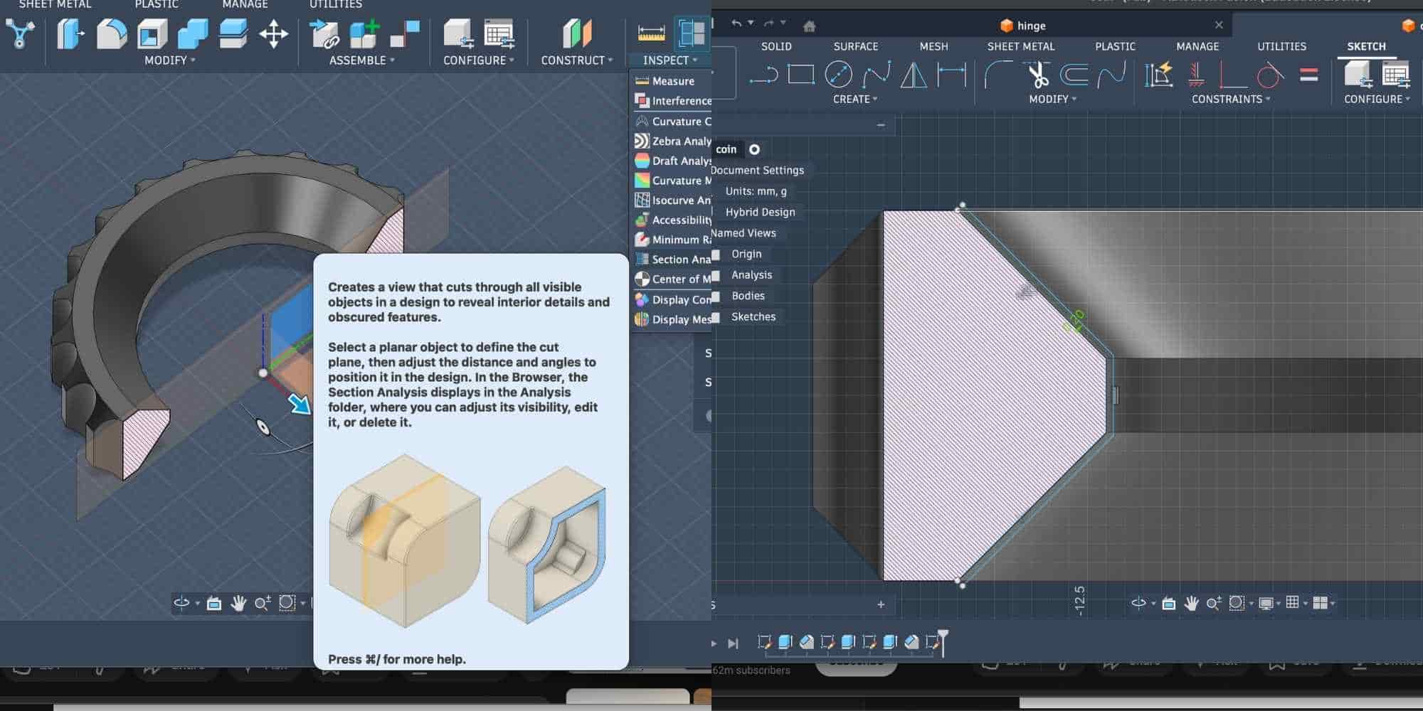
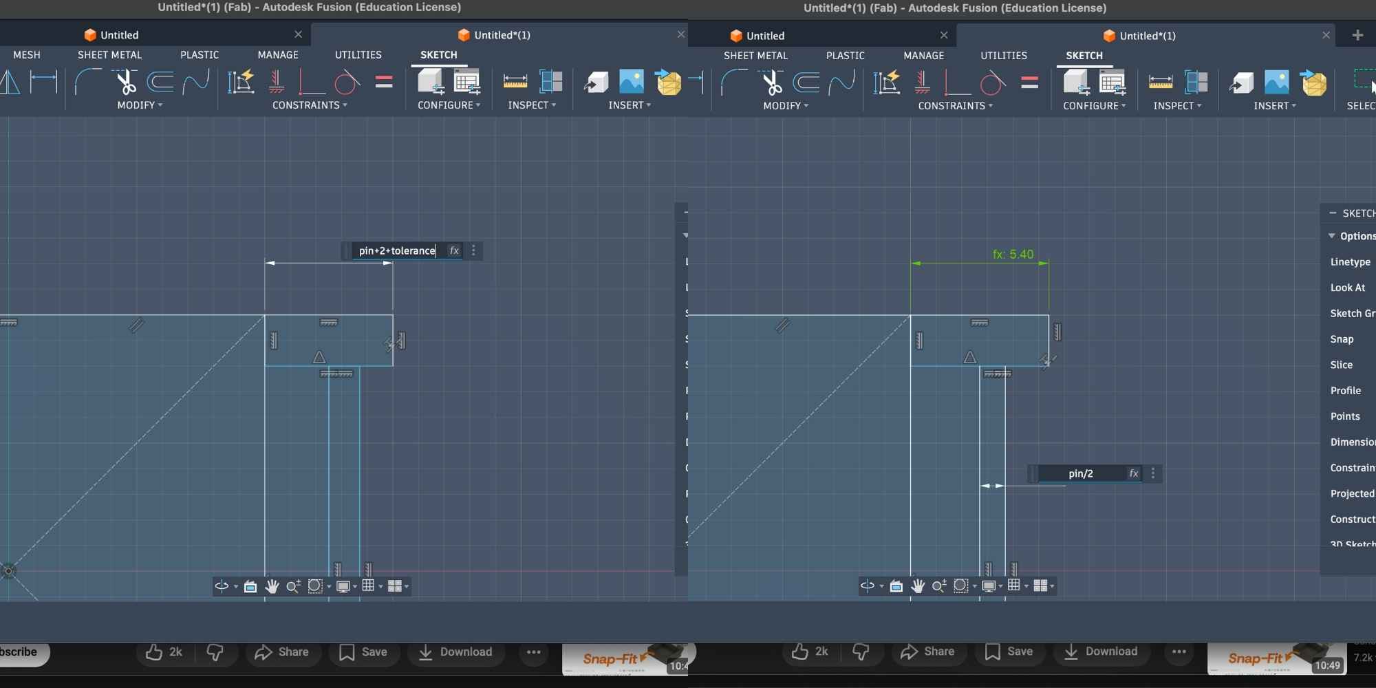
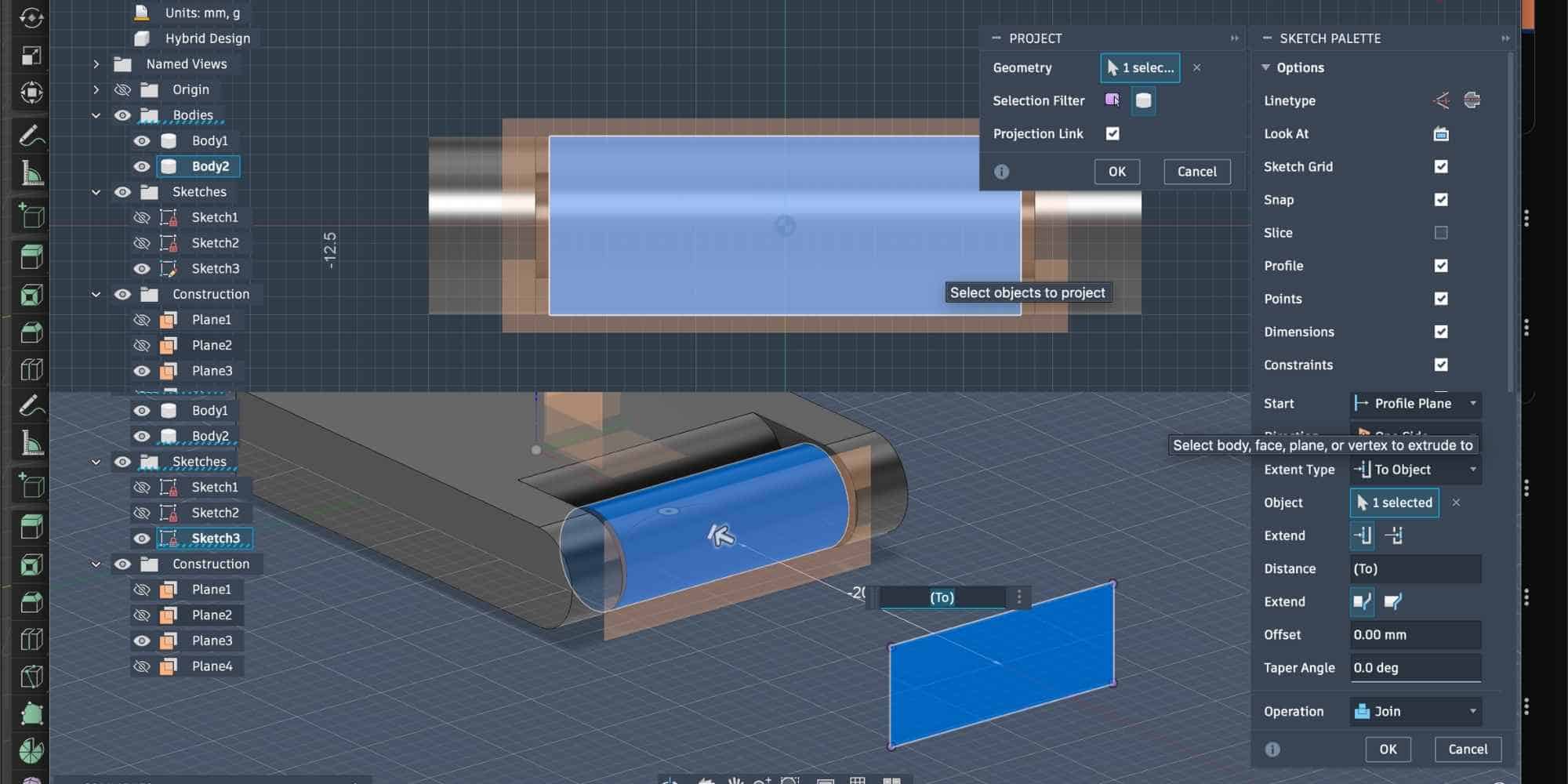
To create something that could not be made subtractively, I needed an internal body printed in place. I used Inspect > Section Analysis and selected the right plane to view the cross-section of the model. From this section view, I traced the inner chamfered profile by creating a new sketch.
I then offset this profile by 0.25 mm to create clearance between the outer body and the inner body. This clearance is critical in 3D printing, too small and it fuses, too large and it becomes loose.
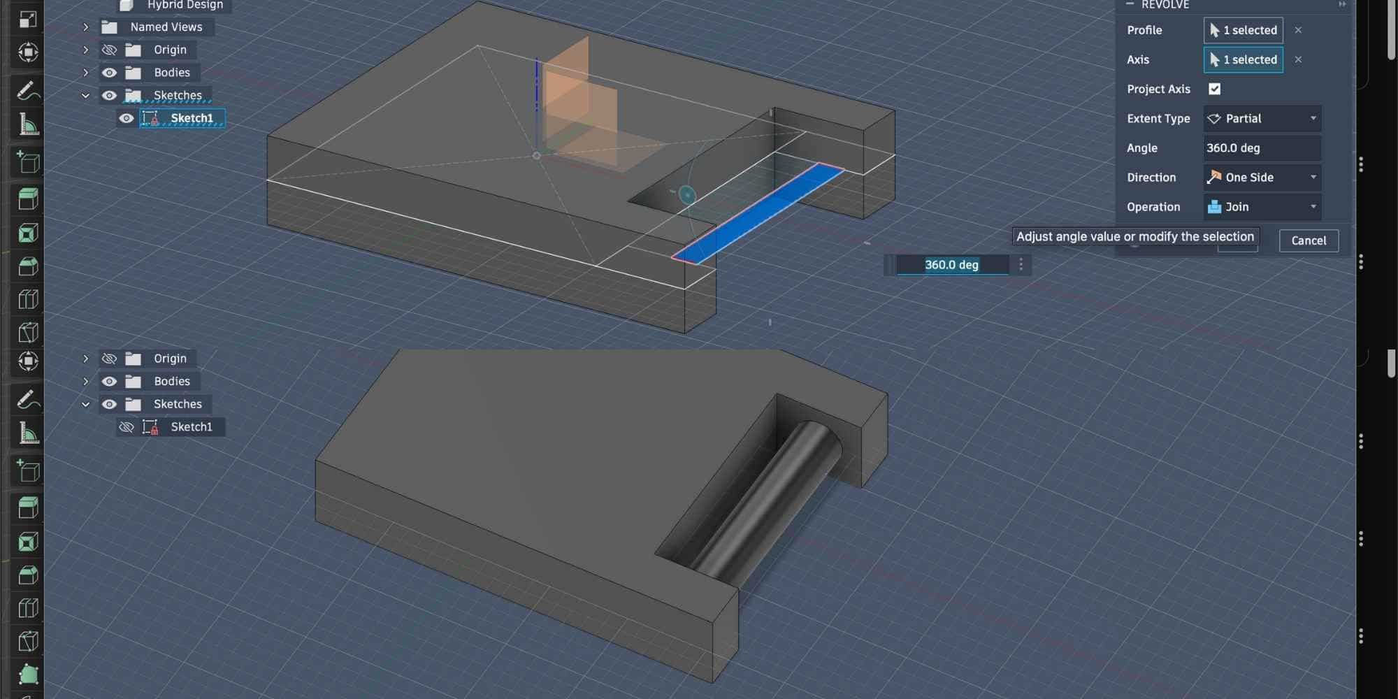
After closing the profile and connecting it to the centre, I revolved it 360 degrees to create a new body inside the first one. This resulted in two bodies:
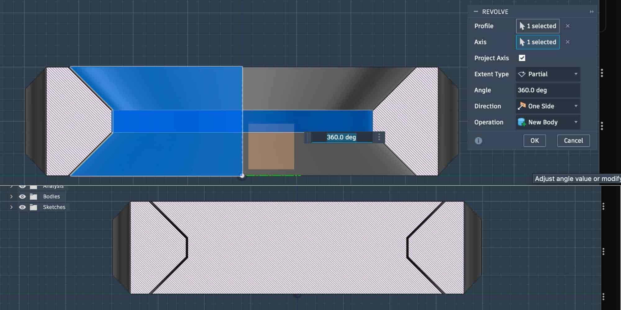
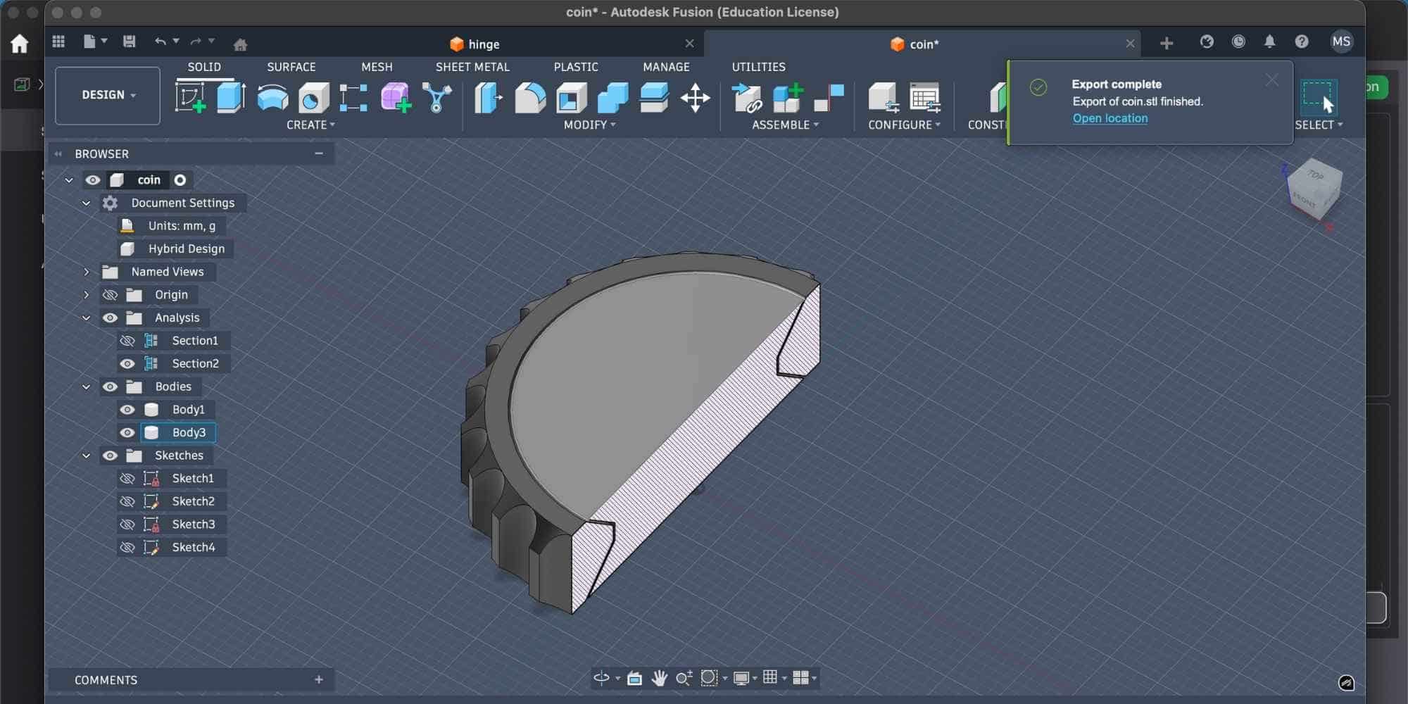
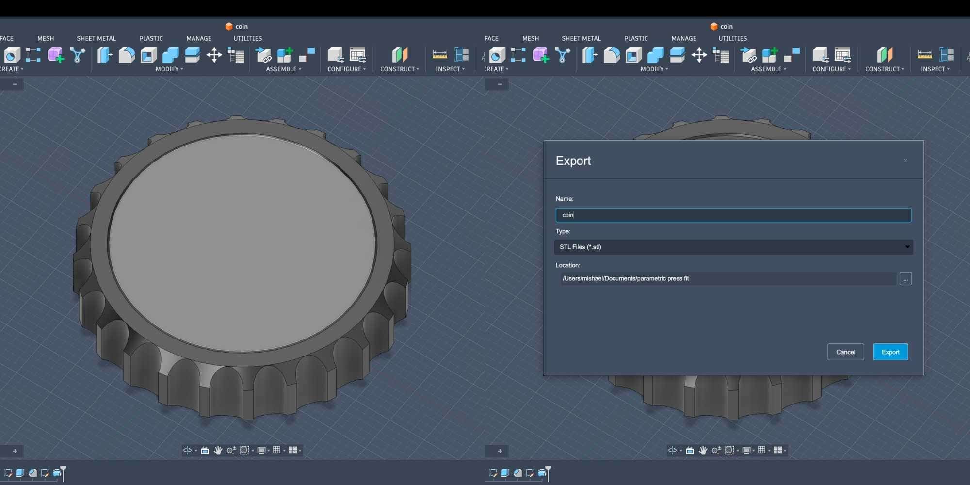
Because the inner body is trapped on both ends and fully enclosed, it cannot be produced using subtractive manufacturing. It can only be created through additive manufacturing. After verifying everything, I hid the section analysis and exported the file in STL format for 3D printing.
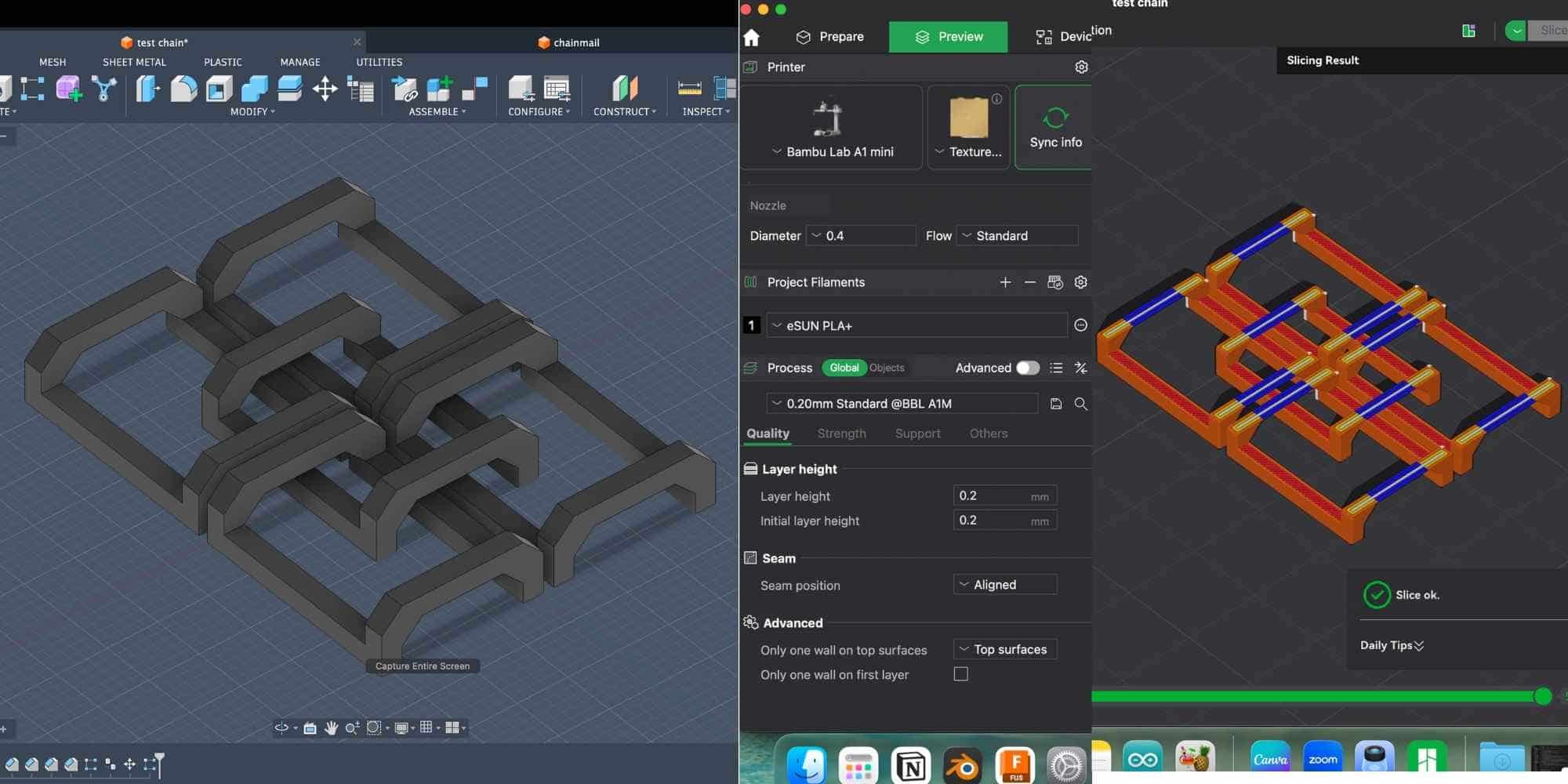
Slicing in Bambu Studio
I opened the STL file in Bambu Studio and configured the following:
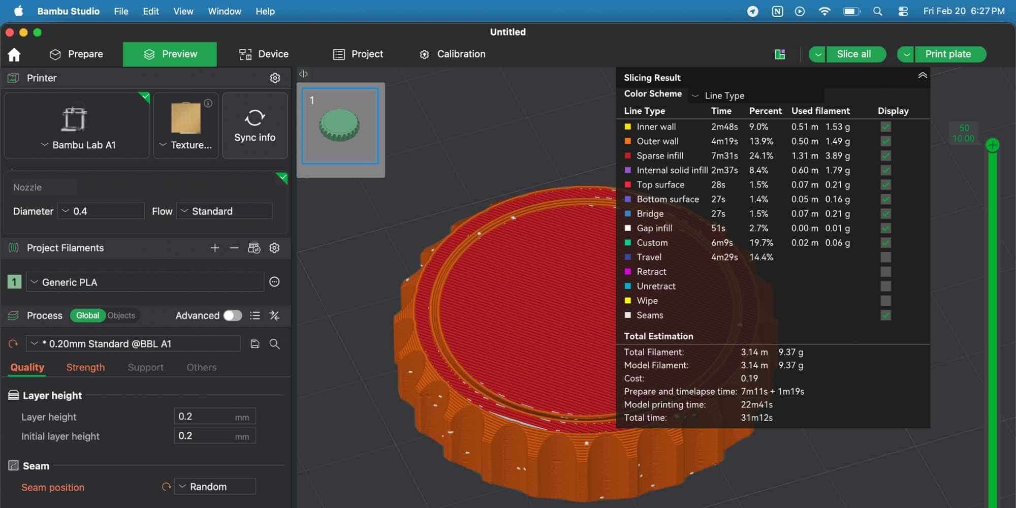
Quality Settings:
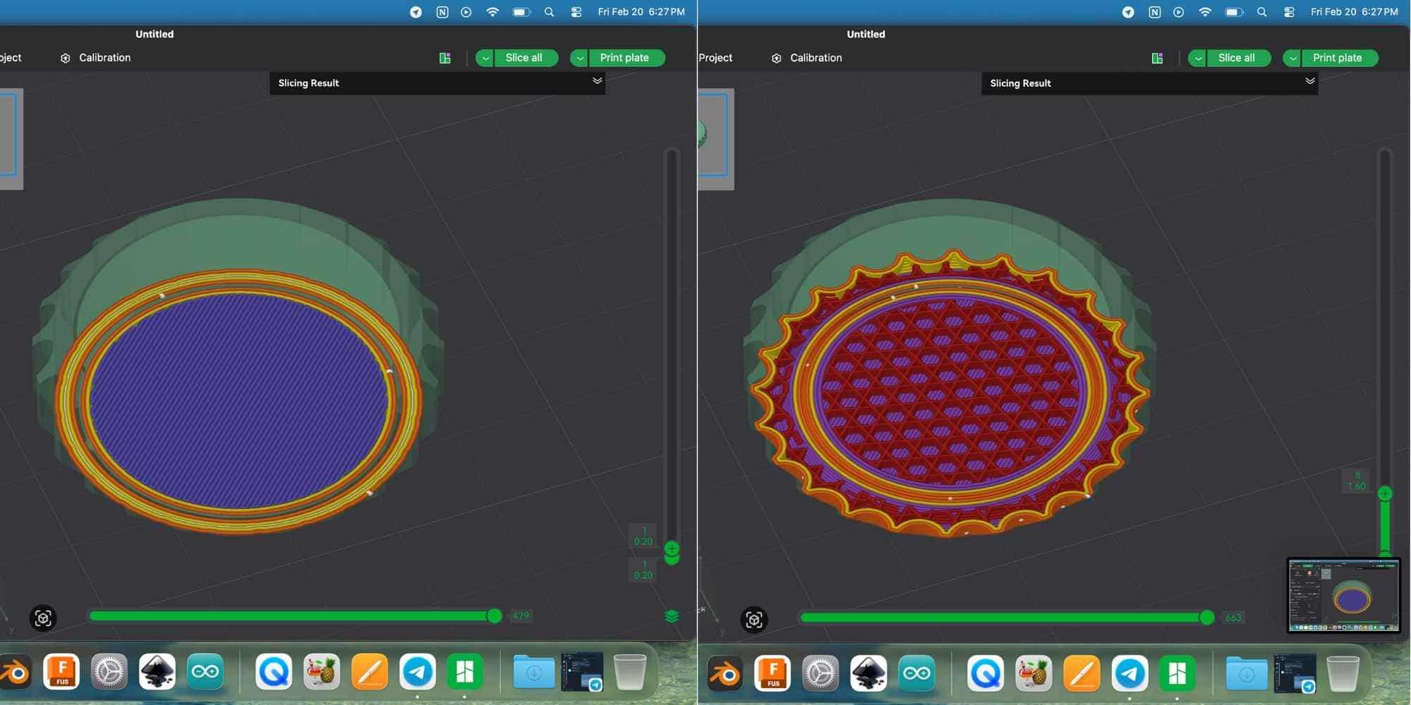
Plate Settings:
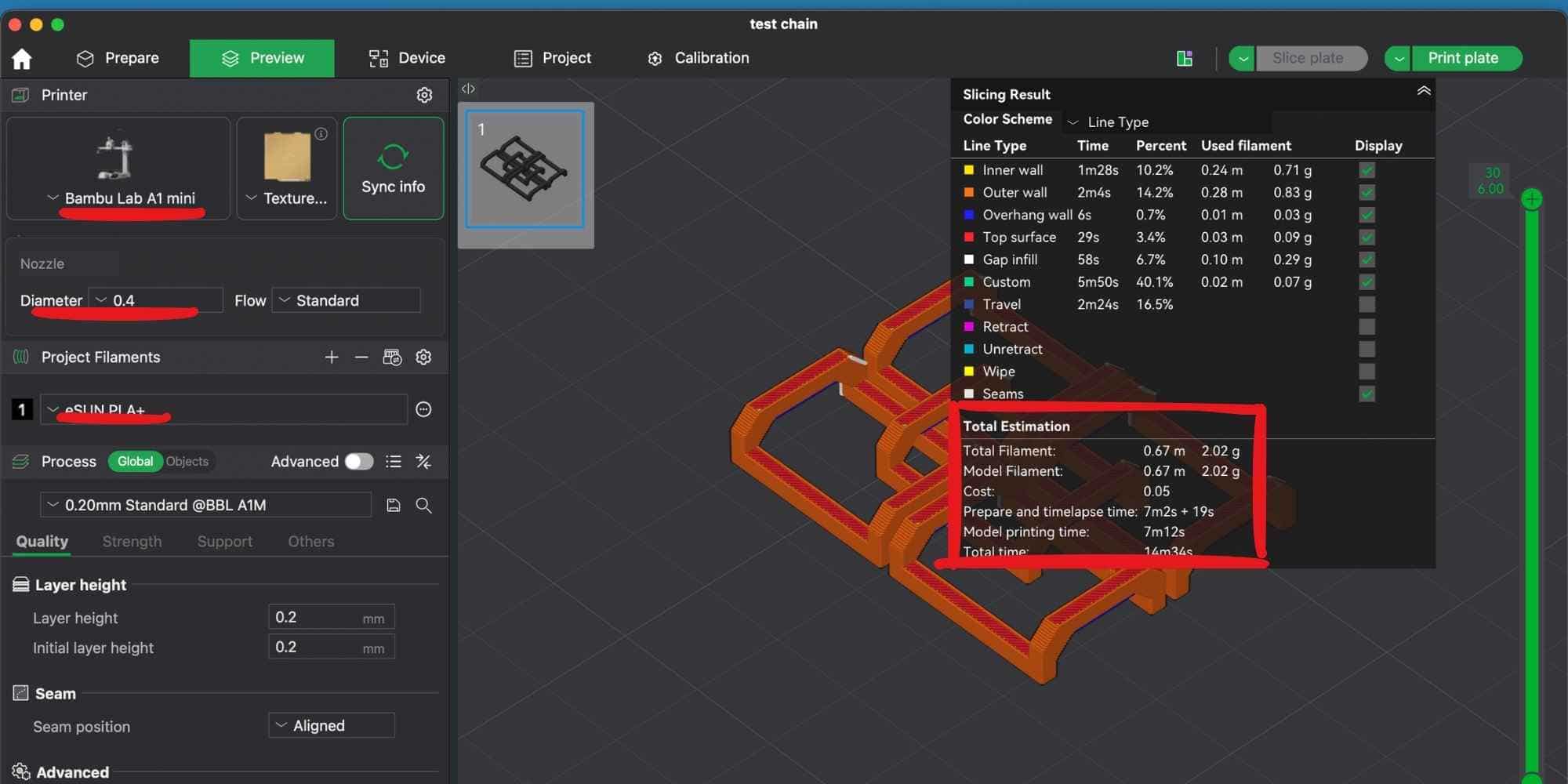
The Total Estimation showed:
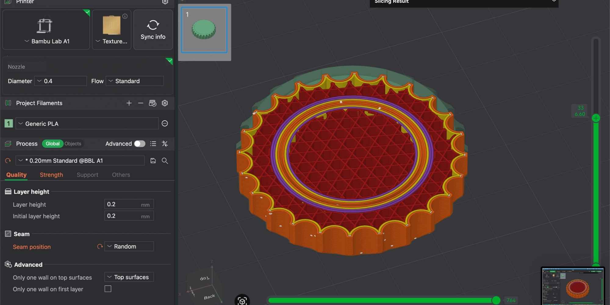
Using the vertical layer preview slider on the right, I performed a slicing “section analysis” to inspect the internal structure. The infill pattern selected was Tri-hexagon, which provides a good balance between strength and material usage. This preview step is important because it confirms:
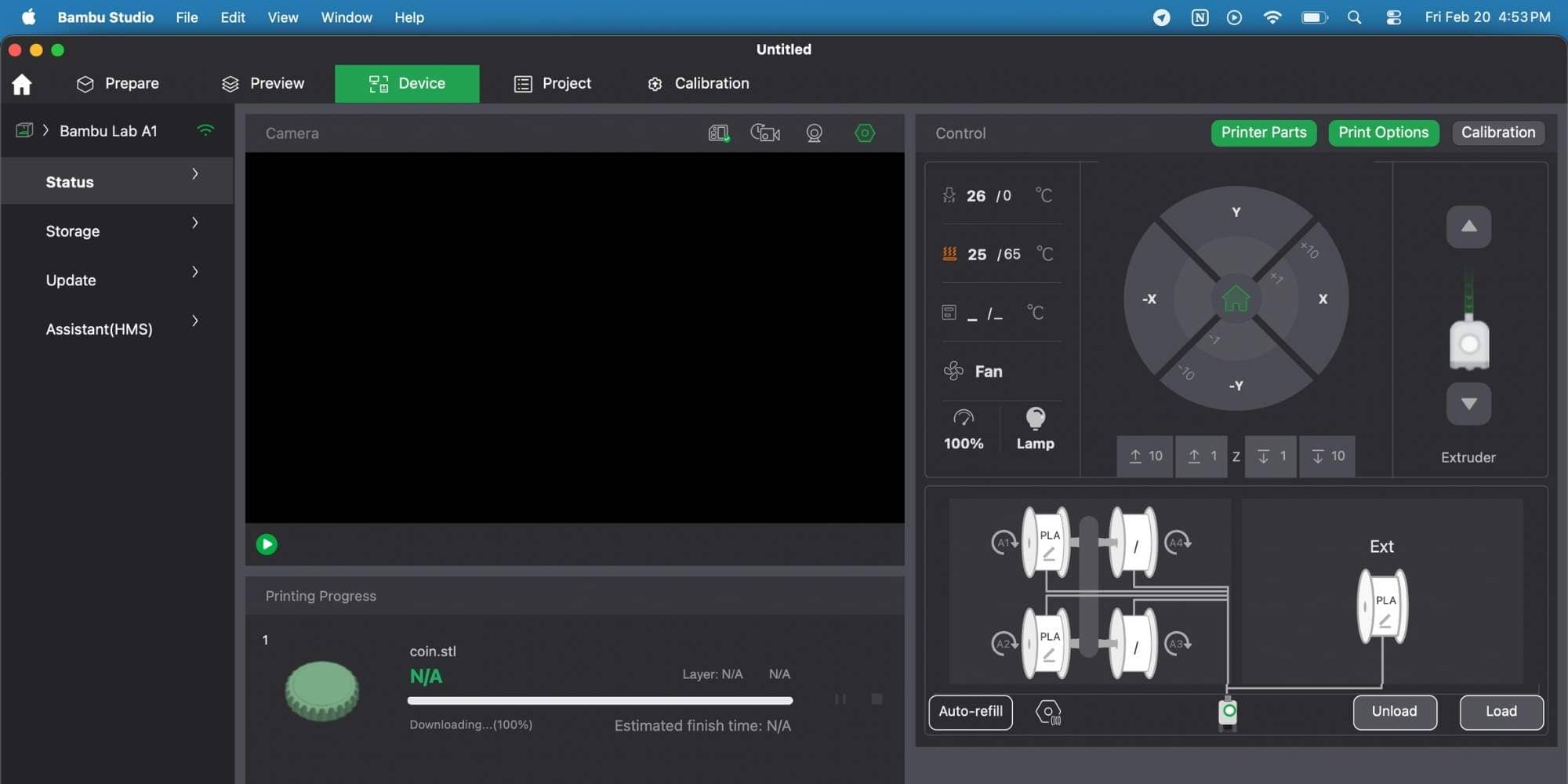
Printing Process (Bambu Lab A1)
After confirming the slicing results, I clicked Print Plate. Before printing, the printer automatically performed:
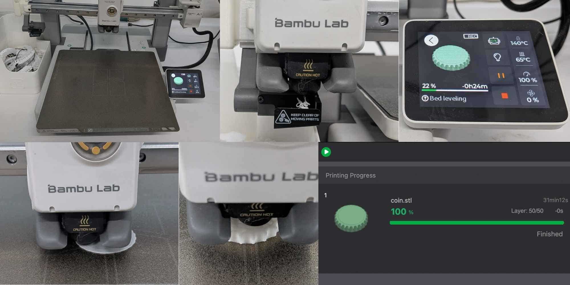
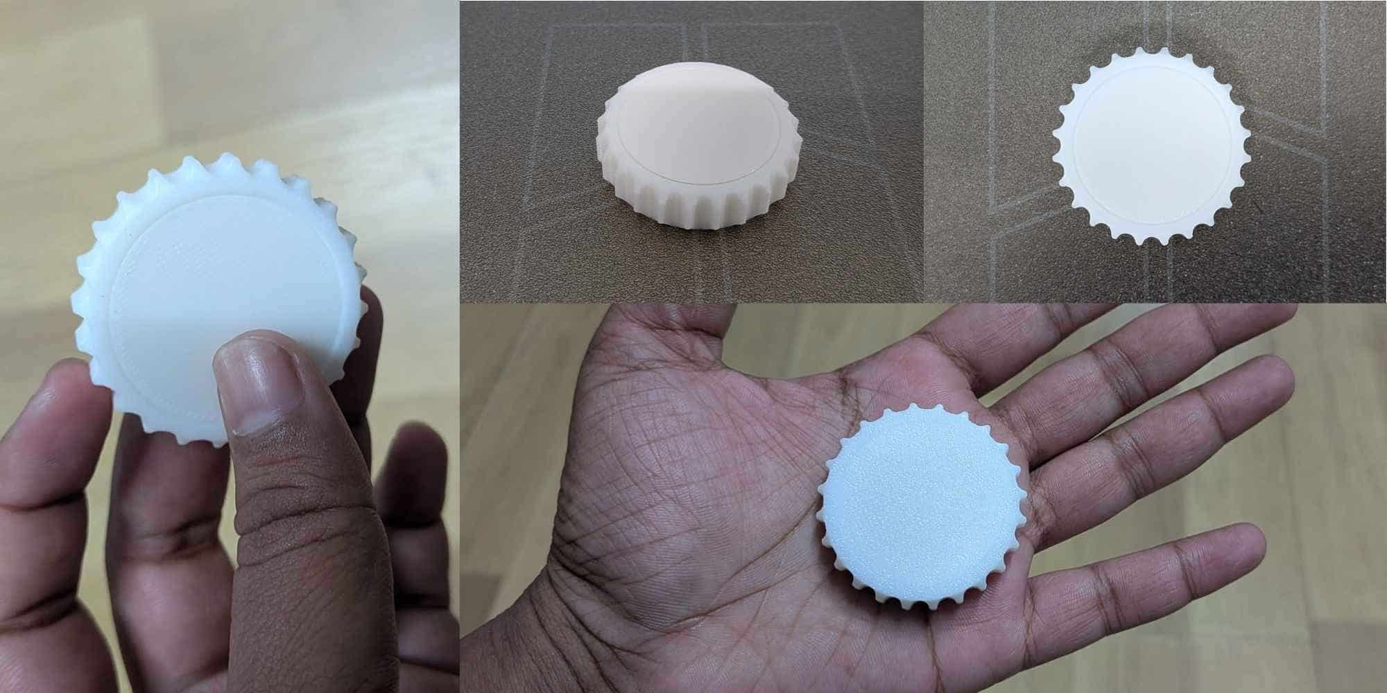
Final Result & Observation
Result and Reflection
After the print completed, I waited for the plate to cool down before removing the part. Initially, a very thin layer of filament sealed the clearance gap. When slight pressure was applied, this thin bridge snapped, freeing the inner body. The internal disc could now rotate freely inside the outer coin. This confirmed:
The object demonstrates additive manufacturing because the inner body is completely trapped within the outer body with no tool access. While the geometry itself is simple and revolved, its enclosure prevents subtractive fabrication unless manufactured in separate parts and assembled later. The ability to print it fully assembled in a single build highlights the advantage of additive manufacturing.
Print-in-Place Parametric Hinge (Fusion 360)
For this exercise, I followed a Youtube tutorial to design a print-in-place hinge with a parametric pin in Fusion 360 and then 3D printed it on the Bambu Lab A1. The objective was to understand how to design moving parts that are assembled during printing, without requiring any post-assembly.
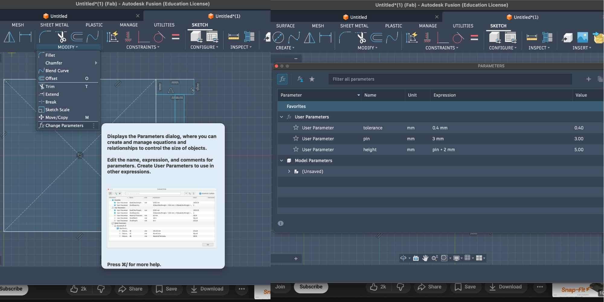
Setting up parameters
Before modeling, I defined user parameters to control all critical dimensions. This ensured the hinge could be easily adjusted later and maintained proper tolerance. The parameters used were:
Using parameters ensured that the clearance between the pin and hinge body remained consistent and could be modified overall if needed.
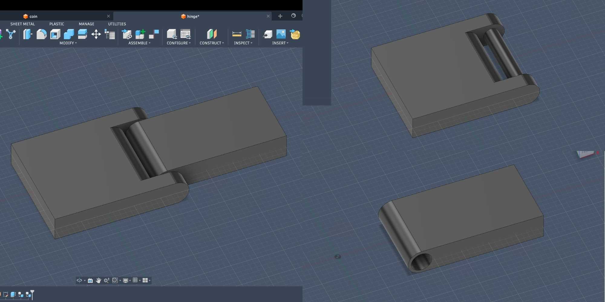
Creating the first hinge body: I first created Hinge 1 as a single solid body by sketching the base profile and extruding it. This formed one side of the hinge and the outer enclosure that would later trap the pin.
To accurately position the pin, I used an Offset Plane. This allowed me to draw on the required plane and sketch directly in the correct internal location. Inside this section view, I sketched a circle using the pin parameter (3 mm) and extruded it along the hinge axis to create the cylindrical pin. Since the hinge was designed as a print-in-place mechanism, the pin remained enclosed inside the geometry.
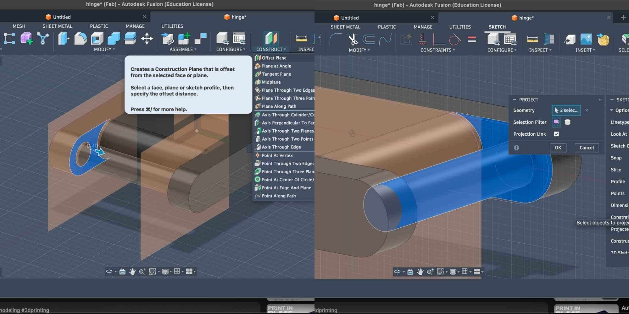
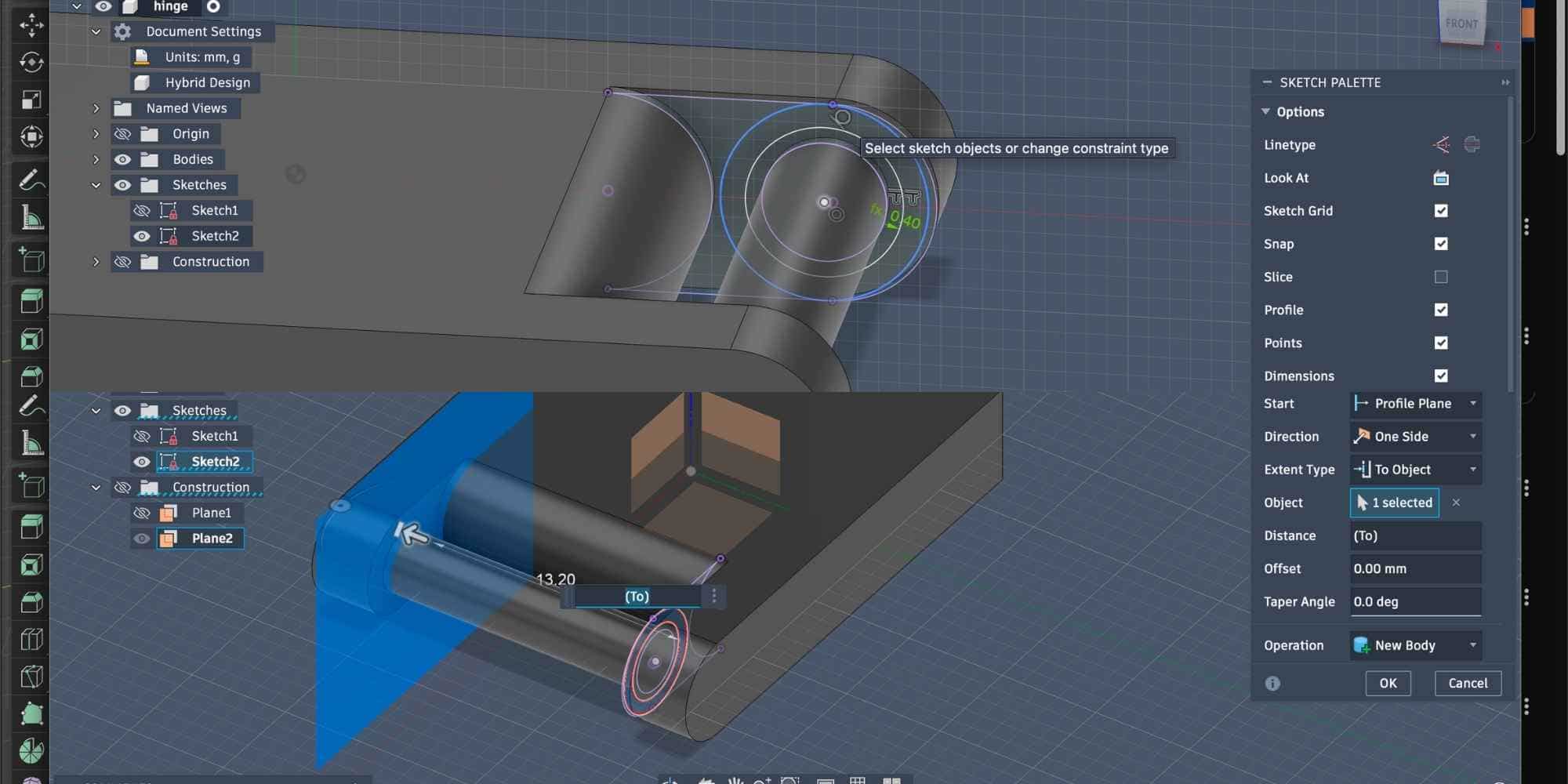
Creating clearance and the second hinge body: After creating the pin, I used the Offset function to generate the required clearance using the tolerance parameter (0.4 mm). This ensured that the surrounding hinge geometry would not fuse with the pin during printing. Using this offset geometry, I then extruded the second hinge body, forming the other half of the hinge while maintaining the defined clearance around the pin. Because all dimensions were driven by parameters, the gap between the pin and hinge body was automatically controlled, ensuring smooth rotation after printing.
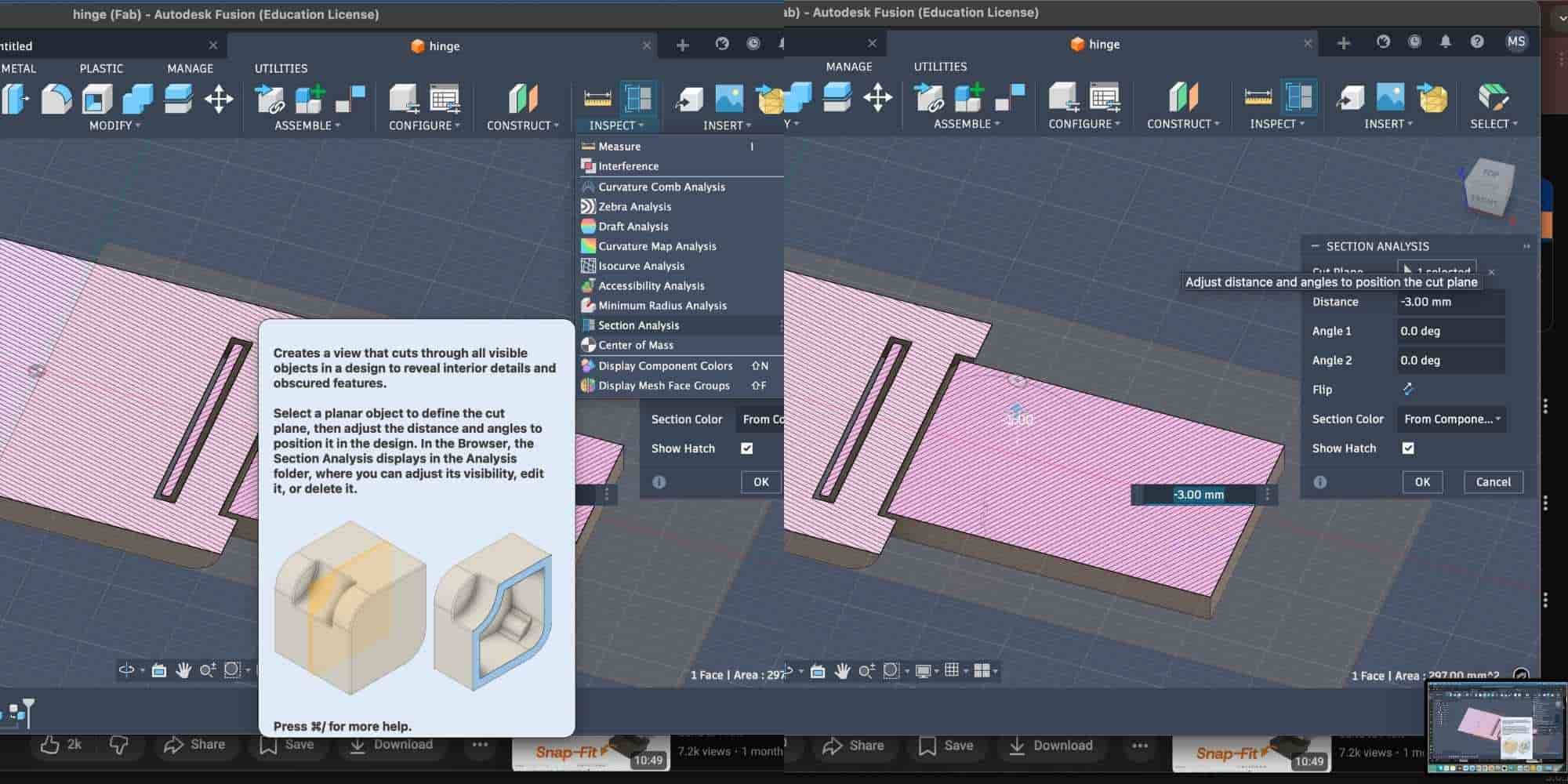
Verifying using section analysis I then used Section Analysis to confirm that:
This step ensured the hinge would function correctly as a print-in-place assembly.
Exporting and 3D printing: The final model was exported as an STL and sliced in Bambu Studio. The hinge was printed flat on the build plate using General PLA, without supports. Print settings:
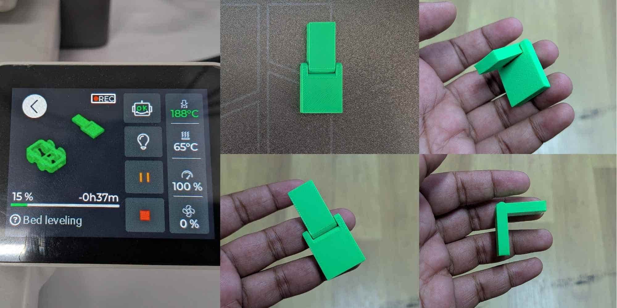
Result: After printing, the hinge was fully assembled as a single piece. Initially, the pin was slightly stiff due to minimal adhesion, but after gently moving it, the hinge rotated freely. The pin remained permanently trapped inside the hinge, demonstrating a successful print-in-place parametric design.
Reflection
This exercise helped me understand:
Both the coin and the hinge were print-in-place assemblies. They are not just static forms, they are systems designed around controlled movement through tolerance.
The coin consists of two bodies printed together, where the outer ring rotates around the inner core. Even though it appears minimal, the functionality depends entirely on clearance. If the gap is too tight, the parts fuse. If it is too loose, the rotation loses precision. This made me understand how small dimensional decisions directly affect motion.
The hinge applies the same principle in a different configuration. The pin and knuckles are printed assembled, and their movement depends on carefully planned internal gaps. Section analysis helped verify that the bodies were not intersecting, and the slicer preview confirmed whether the hinge would print fused or functional. What looks simple in both cases is actually a tolerance study.
These exercises shifted my understanding from modelling shapes to designing internal relationships that enable motion, something that would be extremely difficult, if not impossible, using subtractive methods.
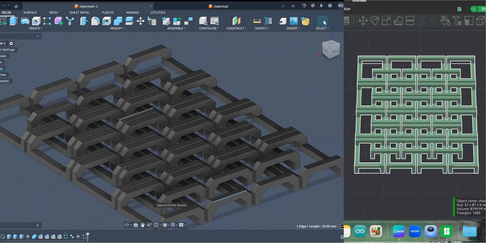
3D Printing Parametric Chainmail in Fusion 360
For this exercise, I created a parametric square-weave chainmail sheet in Fusion 360 by following a Youtube Tutorial by 'Tango of the Geeks' and adapting it. The main goal was to learn how user parameters and formulas can control geometry, so the entire design updates automatically when a single value is changed.
This project uses basic Fusion operations:
Defining the structure
The chainmail link consists of three main elements:
Axis reference used:
I started by sketching four corner squares and four connecting rectangles on the XY plane. These represent the posts and crossbars. The sketch was placed near the origin and aligned so constraints could keep everything stable when dimensions change.
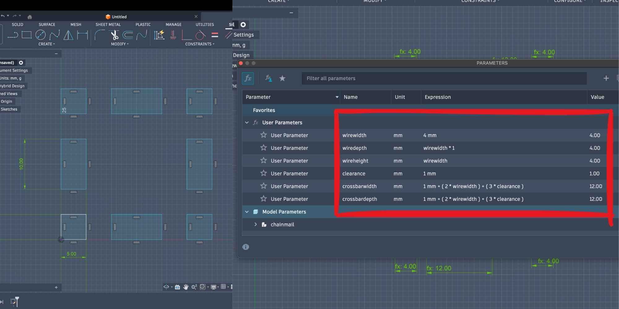
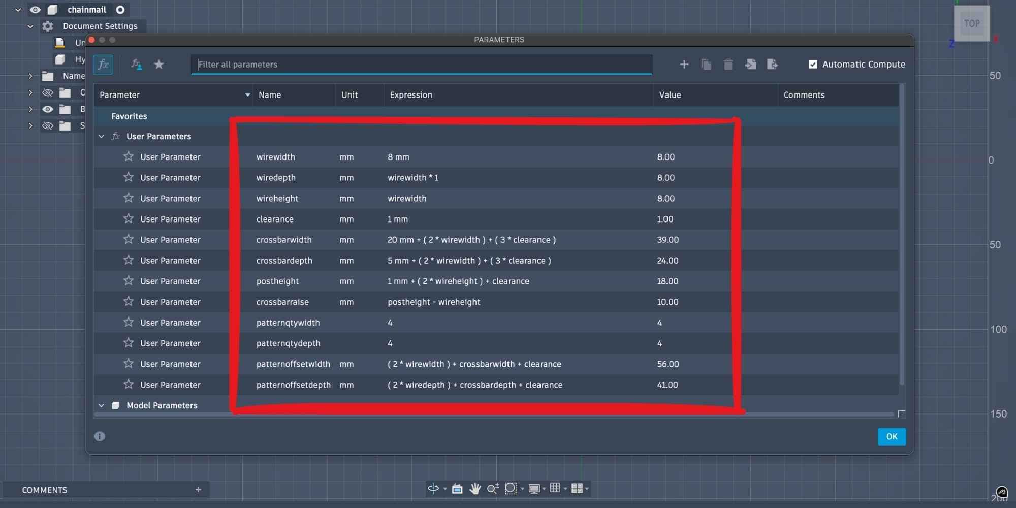
Creating user parameters
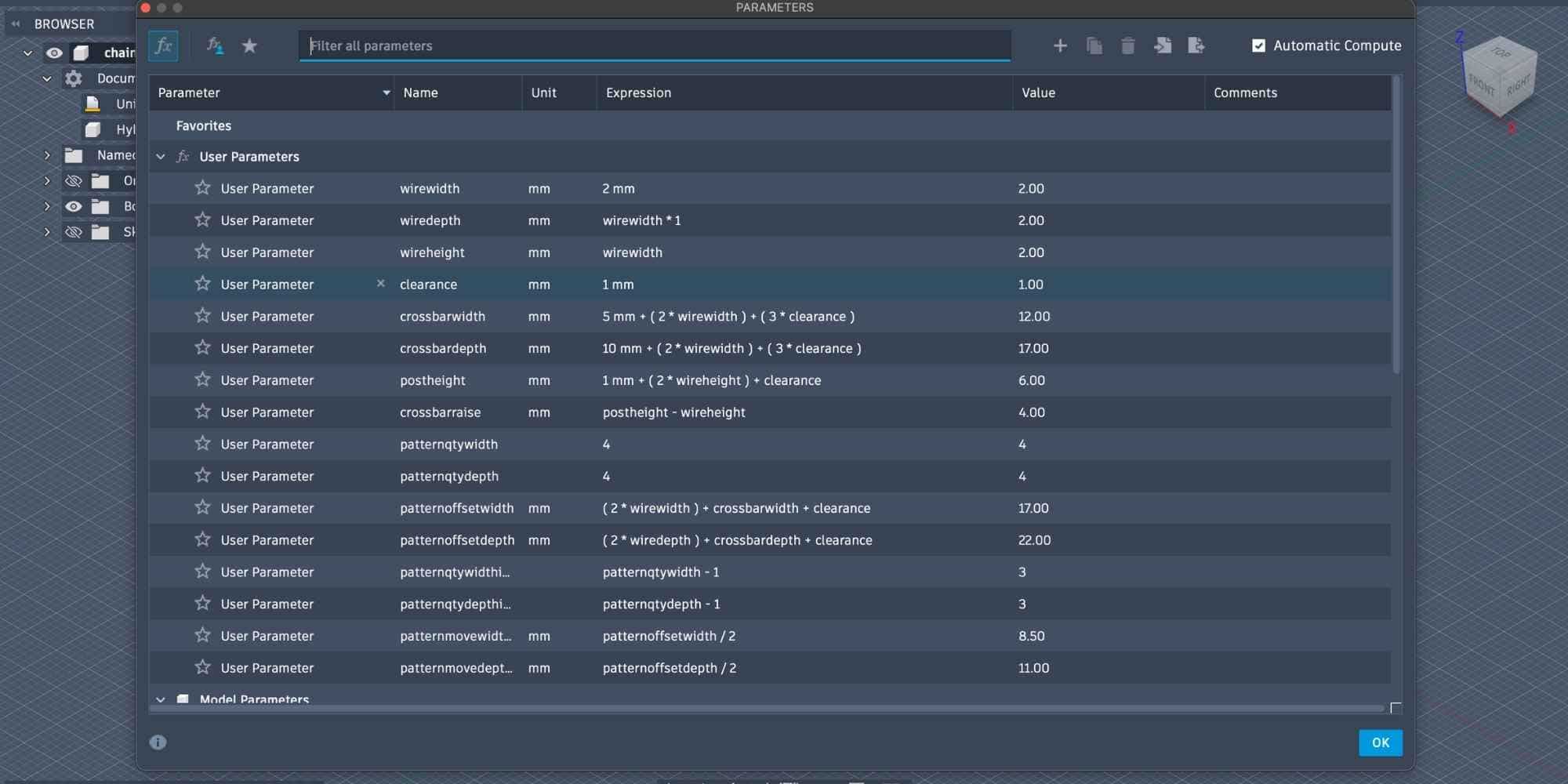
Instead of manually dimensioning everything, I defined user parameters under Modify > Change Parameters. These control the entire model. Basic wire dimensions:
Clearance between moving parts:
Crossbar size was calculated using formulas so two wires and clearances could fit:
Vertical positioning parameters:
These formulas ensure that links interlock but do not fuse, which is critical for print-in-place chainmail.
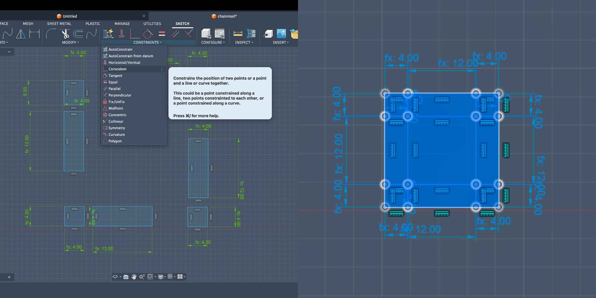
Applying parameters and constraints
I dimensioned each sketch element by typing the parameter names directly into the dimension field (for example, typing wirewidth instead of a number). Constraints such as:
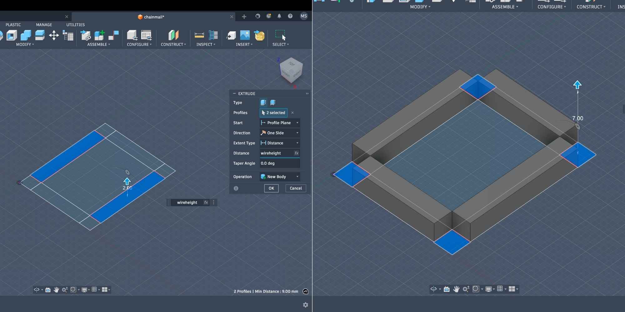
Extruding into 3D bodies
The sketch was extruded into separate bodies:
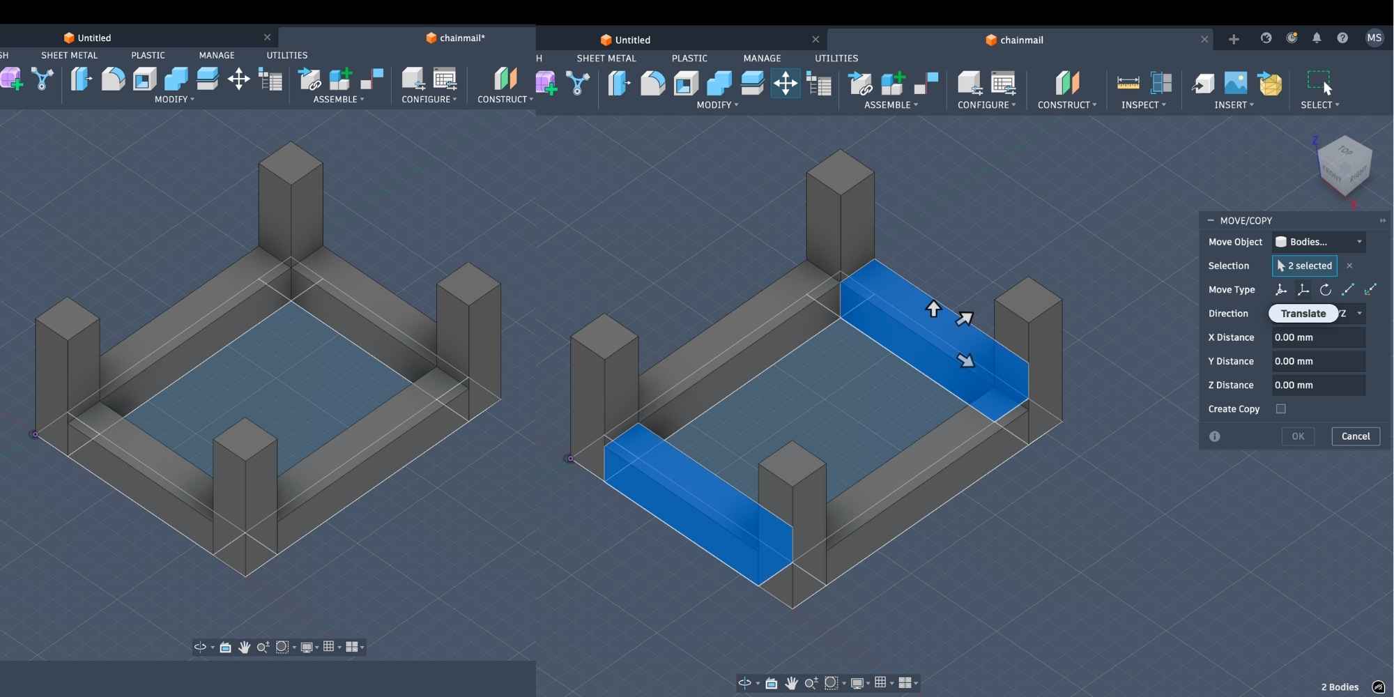
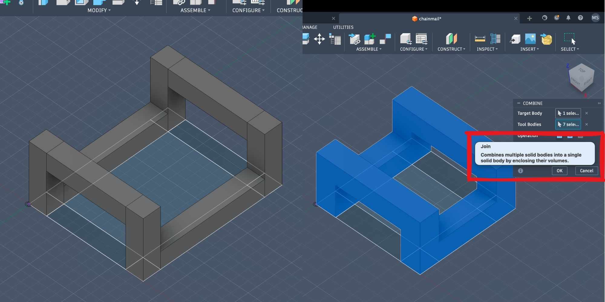
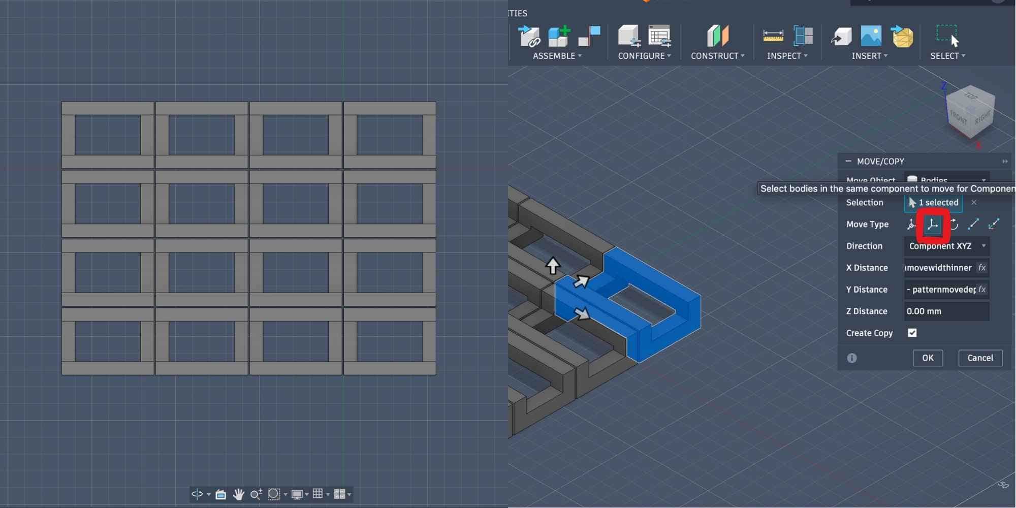
Moving and combining bodies
The upper crossbars were moved upward using: crossbarraise. This was done using the Move tool in Translate mode, entering the parameter name instead of a number. This ensures the position updates automatically if dimensions change. After positioning, all bodies were combined using: Modify > Combine > Join. This converted the separate bodies into a single chainmail link body.
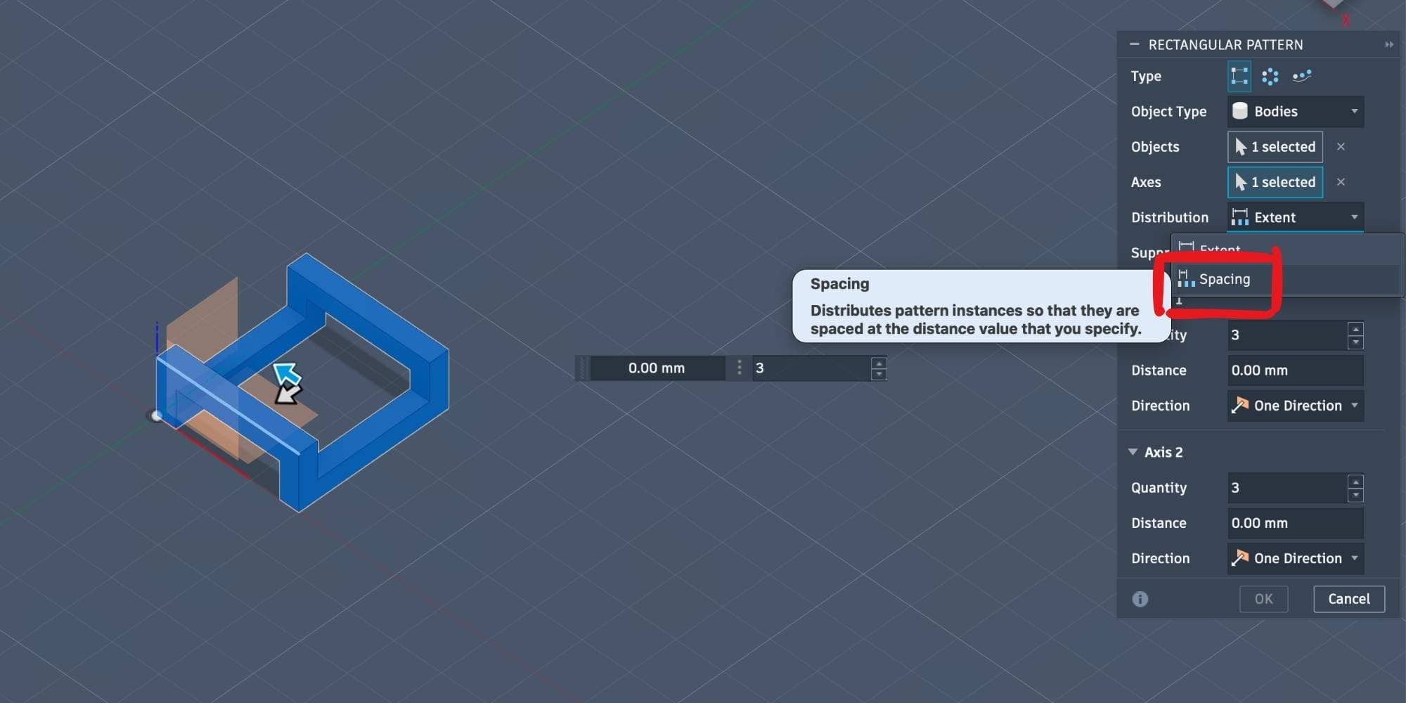
Creating the chainmail pattern
Additional parameters were created to control the number and spacing of links:
Pattern quantity:
Pattern spacing:
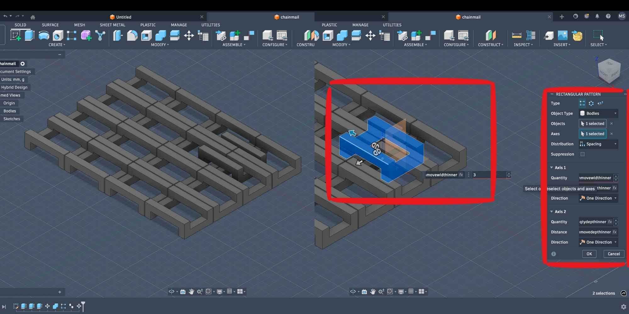
Using Create > Pattern > Rectangular Pattern, I generated a grid of links.
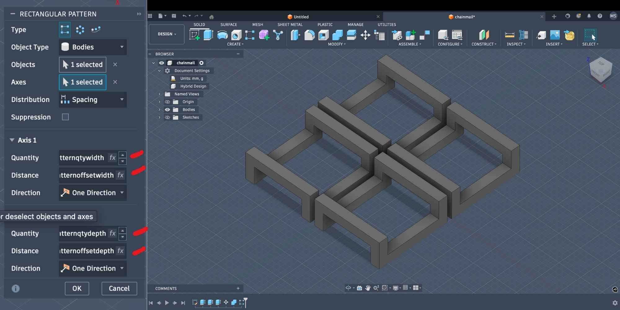
Creating the interlocking inner pattern
To create the woven effect, a copy of the link was moved by half the spacing distance:
Then another rectangular pattern was applied using slightly reduced quantities so the inner links fit between the outer links. This produced a fully interlocked square-weave chainmail sheet.
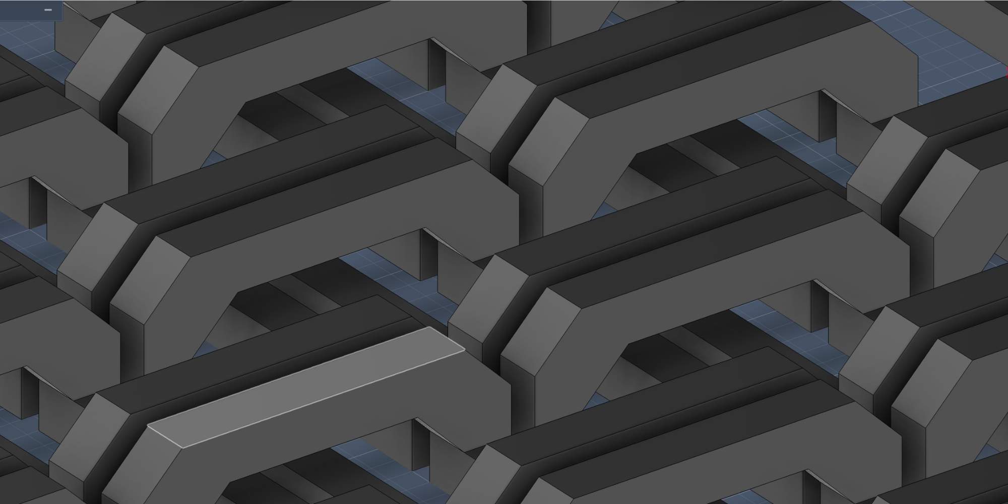
Design improvement: adding chamfers for better printability
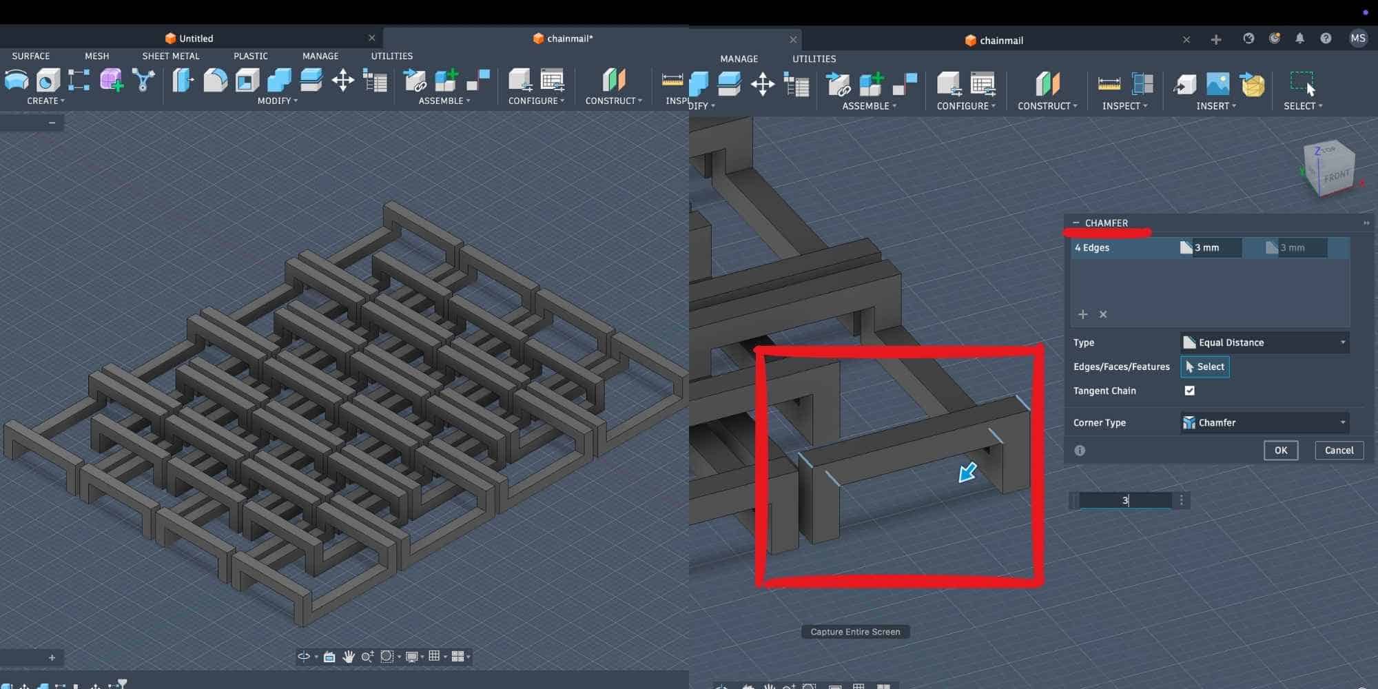
After presenting the chainmail design, I was advised to add chamfers at the crossbar junctions to reduce sagging during 3D printing.
The crossbars originally had flat horizontal edges, which would create unsupported overhangs. Since this is a print-in-place assembly with tight clearances, even small sagging could cause adjacent links to fuse together.
Because the model was fully parametric, I modified it directly through the timeline:
Steps followed:
I applied a 3 mm equal-distance chamfer to the crossbar junction edges, both:
This replaced the sharp 90° corners with sloped faces, making the geometry more suitable for additive manufacturing.
Result
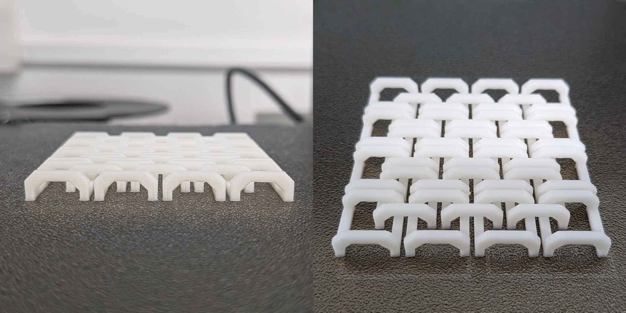
Test print: validating clearance and printability
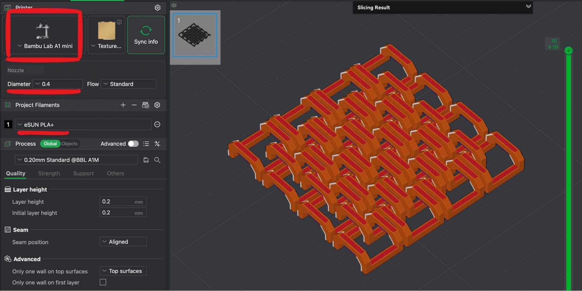
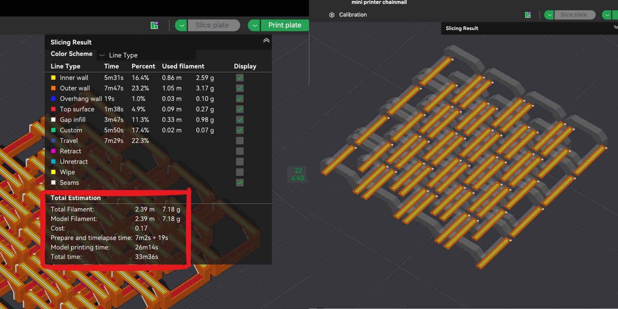
Before printing the full chainmail sheet, I created a small sample section with minimal links to test clearance, chamfers, and overall printability. This helps verify that the links do not fuse and can move freely after printing, while also reducing material and time if adjustments are needed. The sample was sliced using Bambu Studio and printed on a Bambu Lab A1 Mini available in our lab, using eSUN PLA filament. Slicer results:
This quick test allowed me to validate the design before committing to a larger print. The small size makes it easier to observe whether the clearance parameter and chamfers are sufficient to prevent sagging and fusion, which is critical for a print-in-place mechanism like chainmail.
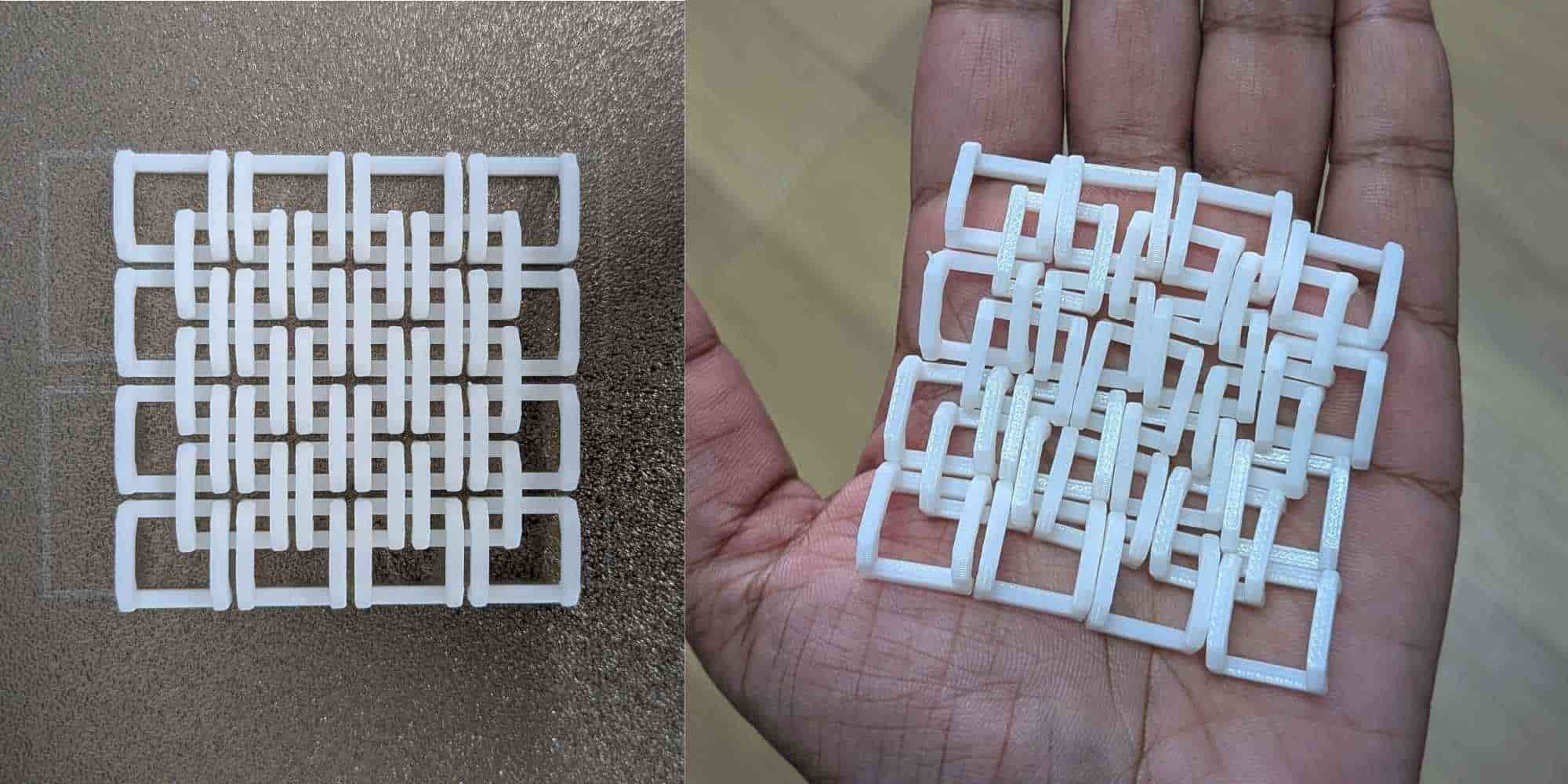
Iteration: adjusting parameters after initial test print
The initial test print completed successfully, and the links printed cleanly without fusing. However, I observed that the overall dimensions of each link were too wide, which allowed adjacent links to pass through too easily and become overly loose and tangled, instead of maintaining a controlled interlocking weave. Since the design was fully parametric, I returned to Modify > Change Parameters and adjusted the values of:
Reducing these dimensions refined the proportions of the links while maintaining the calculated clearances. Because all related features were driven by formulas, the entire model updated automatically, including crossbars, spacing, and pattern offsets. This demonstrated the strength of parametric modeling, where dimensional relationships remain intact while allowing rapid design iteration. After updating the parameters, I exported the revised model and proceeded with another test print using a larger number of links to verify proper interlocking behavior and structural consistency.
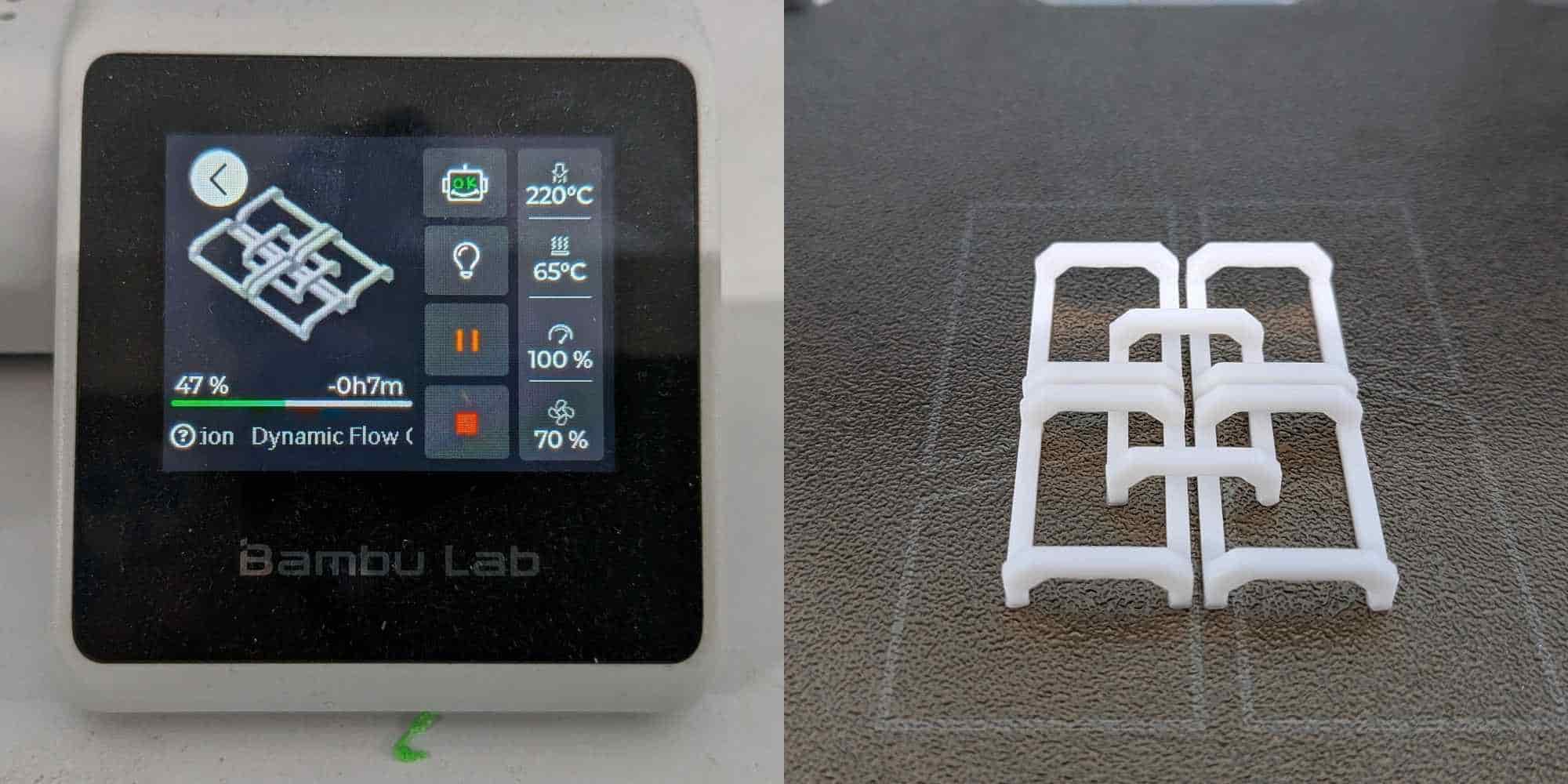
Full test print and troubleshooting adhesion issue
After adjusting the parameters, I prepared a slightly larger chainmail with updated dimensions sample and sliced it in Bambu Studio for printing on the Bambu Lab A1 Mini using eSUN PLA. Slicer estimates:
However, during the first layer, one of the thin link bases lost adhesion and shifted slightly. This caused a misaligned extrusion, which would have ruined the print if continued.
To prevent wasting material, I immediately:
Troubleshooting steps:
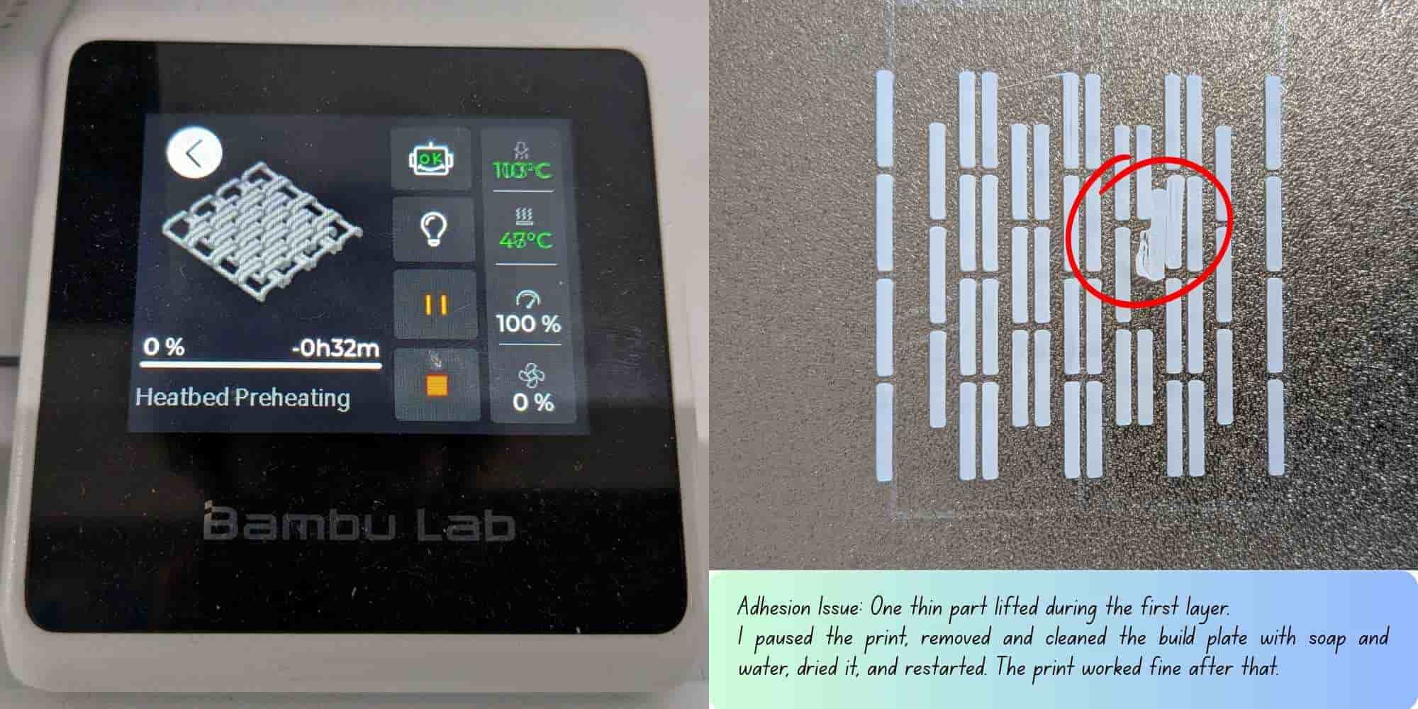
Noticed that the AC airflow was blowing directly onto the printer, which could affect adhesion,then adjusted the flap to avoid direct airflow onto the build plate. After reinstalling the cleaned plate, I used the printer’s "previous print file" list and restarted the print. This time, the first layer adhered properly, and the print completed successfully.
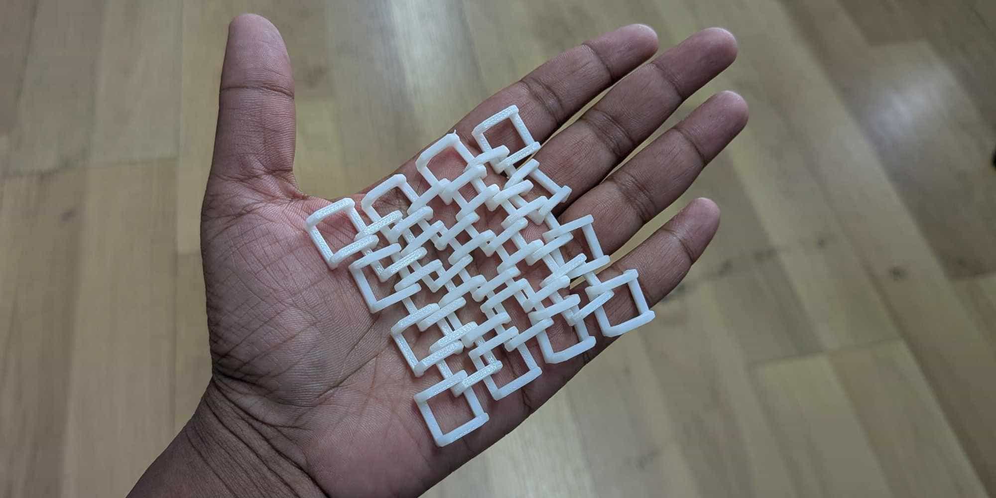
Hero Shot
3D Scanning with the Artec Leo 3D Scanner
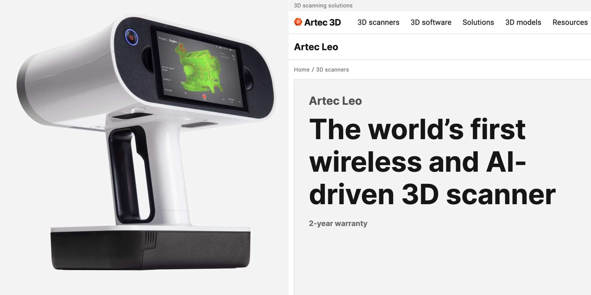
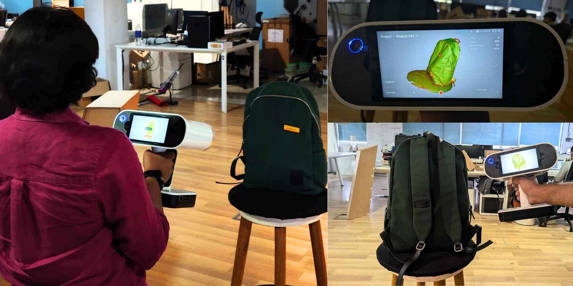
The Artec Leo is a professional handheld 3D scanner designed for fast and accurate data capture. It is fully wireless and standalone, meaning it does not need to be connected to a computer during scanning. It has a built-in battery, onboard processor, and touchscreen display, so the scan can be viewed in real time directly on the device. This made the process feel similar to recording a video, but instead of video, it builds a 3D model.
Key Features
Accuracy and Capture
This allows detailed digital models to be captured quickly and accurately.
3D Scanning My Backpack
For this assignment, I 3D scanned my backpack. While the scanner is handheld and wireless, it is quite heavy (about 2.6 kg), and holding it for a long time becomes tiring. Since the scanner must be moved around the object to capture all sides, this required continuously walking around the backpack and maintaining a steady distance. The captured areas were shown in green on the display, which helped me understand which regions were already scanned and which areas were missing. This real-time feedback was very useful to ensure full coverage. However, if the scanner moved too far away or lost tracking of the object, it would start a new scan automatically. This meant that multiple scan segments were created, which later had to be aligned and stitched together during post-processing. Despite this, the scanner was able to capture a high level of detail, including the overall shape, fabric folds, and surface features of the backpack.
Reflection: This experience helped me understand that 3D scanning is highly dependent on movement and tracking. Maintaining consistent distance and coverage is important to avoid losing tracking. The real-time preview made it easier to identify missing areas, but the weight of the scanner made long scans physically demanding. Overall, the Artec Leo was able to capture detailed geometry and texture, making it suitable for digitizing real-world objects for digital fabrication.
Processing the Scan in Artec Studio 20
After completing the scan, I transferred the scan file from the Artec Leo to the computer via Wi-Fi and opened it in Artec Studio 20. The software interface was well organized, and the instructor walked us through the main sections such as Editor, Tools, Align, Fix Holes, and Texture.
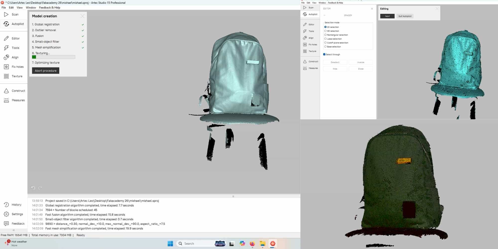
One useful feature is the Autopilot, which guides the user through the processing steps automatically. I first used the Autopilot feature, and it performed operations such as registration, fusion, and mesh preparation. This helped quickly generate an initial mesh from the raw scan data.
After that, I used the Editor, especially the 2D Eraser tool, which was one of the most useful tools. It allows removing unwanted parts of the scan, such as the stool and background that were captured along with the backpack. The tool provides different selection options, including lasso selection, which made it easier to select irregular areas and clean the scan.
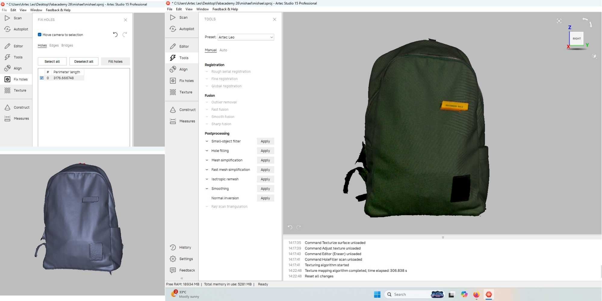
Next, I used the Fix Holes tool to patch missing areas in the mesh. Some holes were present due to occluded areas during scanning, and this tool helped close those gaps and create a more complete surface. Finally, I applied the Texture tool, which mapped the color information onto the mesh. This restored the actual appearance of the backpack, including its color and surface details. It was then exported as OBJ File.
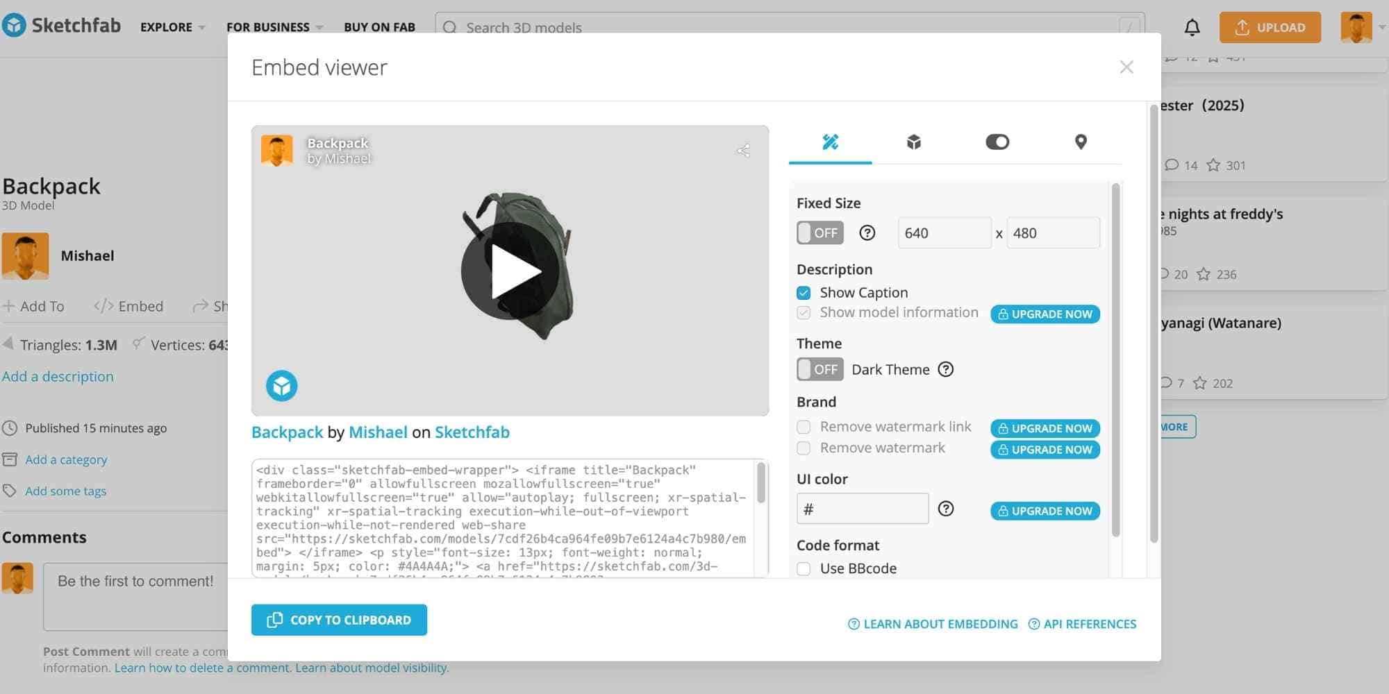
3D Scan File Sharing and Preview
The processed 3D scan files were approximately 94 MB, which was too large to host directly on the webpage. To make them accessible for viewing, I uploaded the files to Sketchfab and used the embedded viewer link to display the model here for interactive preview.
Reflection: I found the workflow in Artec Studio 20 easy to understand and structured. The Autopilot feature made the initial processing fast, while manual tools like the 2D Eraser and Fix Holes allowed more precise cleanup. This step made me realize that post-processing is essential to turn raw scan data into a clean and usable 3D model.