Week 4: Embedded Programming
This week was focused on understanding and working with embedded systems in practice. For the group assignment, we demonstrated and compared different toolchains and development workflows used for various embedded architectures, so we could understand how programming and debugging differed across platforms. For the individual assignment, I dived into a microcontroller datasheet to understand its features and architecture, then wrote and tested a program on a microcontroller-based system that interacted with input and/or output devices and communicated through a wired or wireless connection. Essentially, this week moved from theory into actually reading, programming, and making a microcontroller do something real.
Saheen guided us this week.
Group Assignment: Toolchain & LED Blink Comparison
This comparison focuses specifically on toolchain setup and LED blink implementation across four microcontroller platforms. The evaluation is based only on practical experience with development environment configuration and basic GPIO blinking.
| Board | Development Environment | Programming Level | Build Process | Flashing Method | Blink Implementation Style | Observed Complexity |
|---|---|---|---|---|---|---|
| Arduino Q (UNO R4 WiFi) | Arduino IDE / Arduino Cloud | High-level C++ | Automatic compile & upload | USB (One-click) | digitalWrite() | Very Easy |
| ESP32-C6 | VS Code + ESP-IDF | C / Assembly (RISC-V) | idf.py build (manual build system) | idf.py flash | Direct GPIO register control | High |
| ESP32-S3-DEV-KIT | VS Code + PlatformIO | C++ (Arduino Framework) | PlatformIO build system | USB via PlatformIO | digitalWrite() / NeoPixel library | Medium |
| ATtiny44/84 | Microchip Studio + AVR-GCC | Embedded C | Compile → Generate HEX | AVRDUDE + ISP Programmer | Direct PORT register manipulation | Medium (Low-level) |
Summary Observations
Conclusion
The comparison highlights how toolchain structure and abstraction level vary significantly between platforms. While all four boards successfully executed a basic LED blink program, the setup complexity, build process, and programming depth differed substantially. This demonstrates how architecture and ecosystem design directly influence the embedded development experience.
Individual Assignment: Where I Started From
The last time I wrote any code was around 12 years ago in school. I never used it again after that. So this week felt strange in two ways: I was excited to finally use coding in a real, physical way, but at the same time I felt like I was starting from zero. On top of that, I have never worked with electronics before. So I wasn't just revising programming, I was learning how electricity behaves, what resistors do, and why hardware can break if wired incorrectly.
What made embedded programming different from anything I had done before was that mistakes are not just errors on a screen. A wrong value in your code can mean an LED that never turns on. A miswired component can mean a board that stops responding. The feedback loop is physical, not just logical, and that changes how you have to think.
Before I could make anything work, I had to build up a basic mental model of how microcontrollers operate: what a chip actually is, how a program gets onto it, how it talks to the outside world through pins, and what happens when power is applied. Here are the concepts that became meaningful to me this week.
Microcontroller
Getting Started with Seeed Studio XIAO RP2040I am working with the XIAO RP2040. This is a small development board made by Seeed Studio. Inside it is a microcontroller chip called the RP2040, made by Raspberry Pi. A microcontroller is basically a small computer on a chip. It has:
GPIO
GPIO stands for General Purpose Input/Output. These are the pins that let the microcontroller interact with the outside world.
void setup()
The void setup() function initializes settings, configures pin modes,
starts libraries, and initializes serial communication. It runs only once
when the board is powered on or reset, preparing the environment for
void loop().
void loop()
The void loop() function executes the main logic continuously.
It runs after setup() completes and repeats endlessly
until the board is powered off or reset.
pinMode()
Before using a pin, I must define its behavior.
pinMode(YELLOW, OUTPUT);
pinMode(BUTTON, INPUT_PULLDOWN);
If not defined correctly, the hardware does not behave as expected. This helped me understand that hardware behavior must be explicitly declared in software.
digitalWrite()
This sends a voltage signal to a pin. I used it to:
- Turn LEDs on
- Turn LEDs off
- Create blinking patterns
Although it appears as a simple function, it actually controls physical voltage on the board.
digitalRead()
This reads the voltage level of a pin. I used it to check whether the button was pressed, which made my project interactive instead of running automatically.
Logic Level (HIGH / LOW)
Digital pins operate using two logic levels:
XIAO RP2040 Board
Datasheet Seeed Studio XIAO RP2040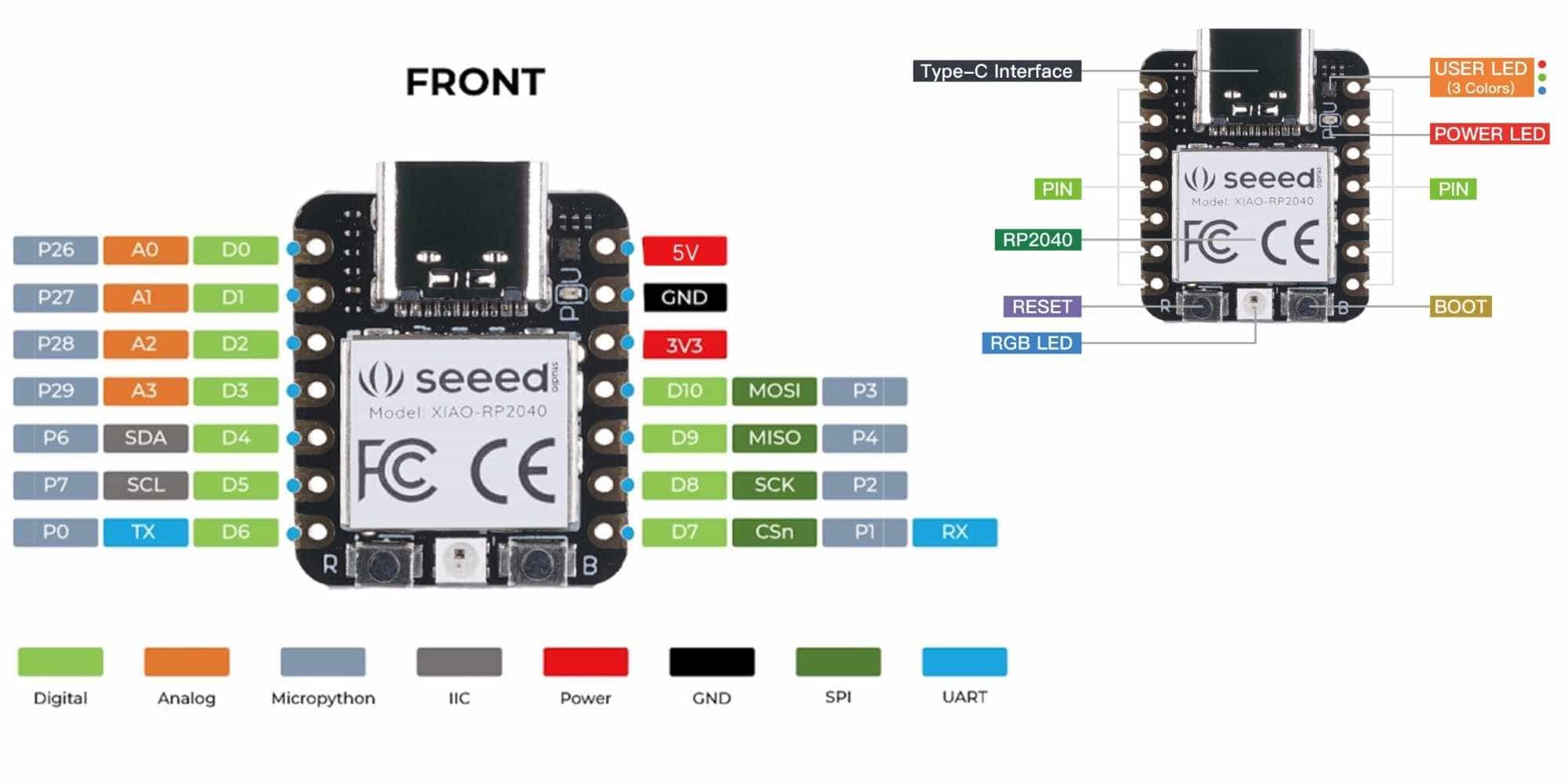
Board Overview
The XIAO RP2040 is a compact development board made by Seeed Studio. It is built around the RP2040 microcontroller chip. The board is roughly thumb-sized and is designed to be breadboard-friendly.
Physical Connections
At the top of the board is a USB Type-C interface, which is used for both powering the board and uploading programs from a computer.
Along the two sides of the board are 14 pins in total. Each pin can serve multiple functions depending on how you configure it in your program:
What I found important to understand is that most pins are multi-function. The same physical pin can act as digital, analog, or a communication pin depending on what your program tells it to do.
Onboard Components
Looking at the back of the board diagram, there are several built-in components that do not need any external wiring:
GPIO and Pin Understanding
Before I could wire anything up, I needed to understand what the pins on the board actually are and how they work.
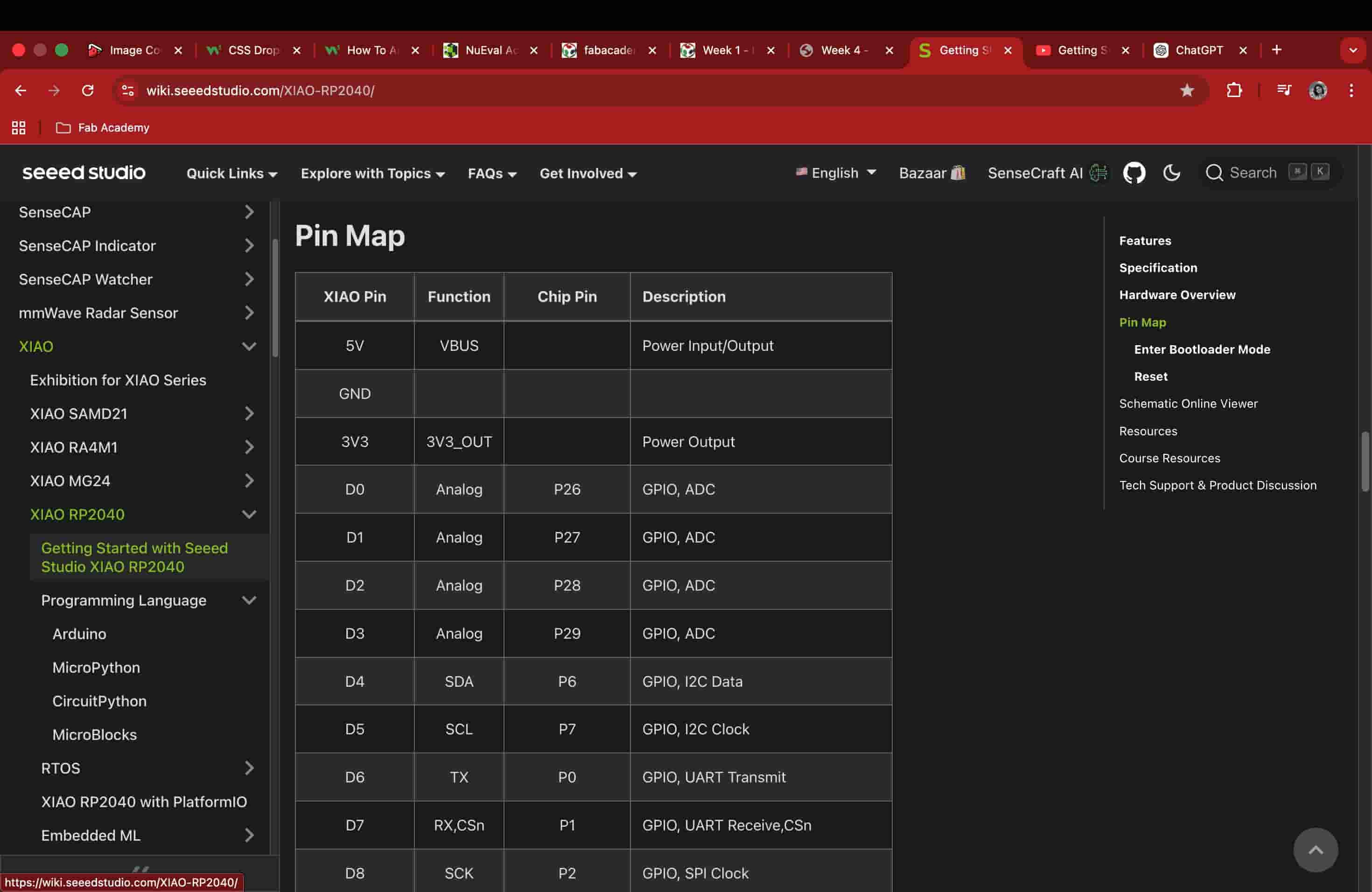
Pin Mapping Between Chip and Board
The datasheet shows internal GPIO numbers, but the XIAO board uses different labels. I had to refer to the XIAO pin map to understand which board pin corresponds to which internal GPIO number. This explains why the default Blink example did not work initially. It was written for a different board configuration.
Memory and Program Storage
From the datasheet summary, I understood that:
This helped me understand what actually happens when I upload code and power the board.
Reset and Boot
From the datasheet, I learned what these buttons actually trigger at the hardware level:
I had seen these buttons on the board already, but reading the datasheet made it clear that they are not just convenience features. They control specific hardware behaviour inside the chip itself.
RP2040
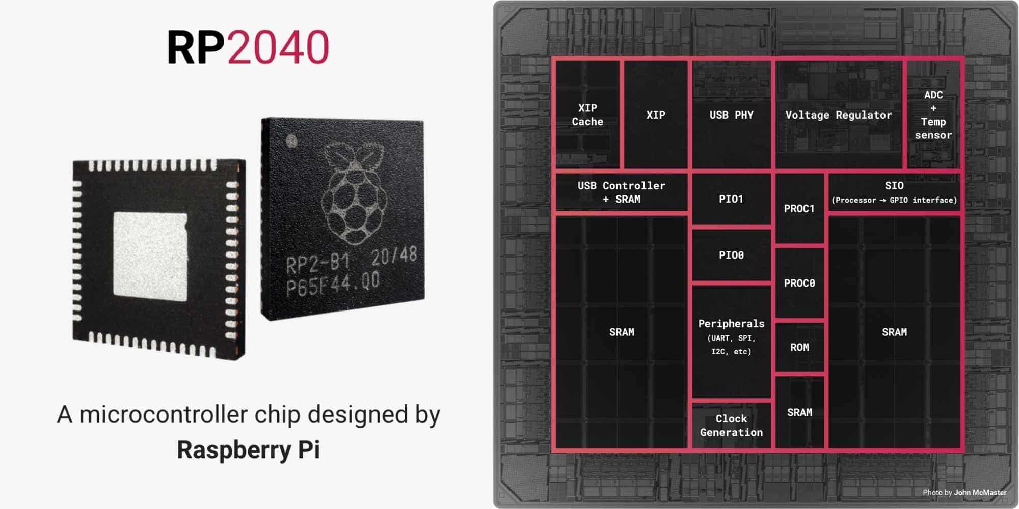
The RP2040 is the microcontroller chip made by Raspberry Pi that sits inside the XIAO RP2040 board. Everything I read in the datasheet this week refers to this chip specifically, not the board around it.
Why Is It Called RP2040?
The name is not random. Each part of it encodes something about the chip's design:
Overview of the Chip
The RP2040 is a dual-core ARM Cortex-M0+ processor. Both cores can run simultaneously at up to 133 MHz, which allows the chip to handle multiple tasks at the same time. Each core is a 32-bit processor. At 133 MHz, the chip can execute up to 133 million clock cycles per second, which gives it significantly more processing capability than traditional 8-bit microcontrollers.
It has 264KB of SRAM built into the chip itself, used while a program is running. It has no built-in flash storage, which is why any board using this chip (like the XIAO) needs to provide its own external flash memory.
Key Features
GPIO Pins
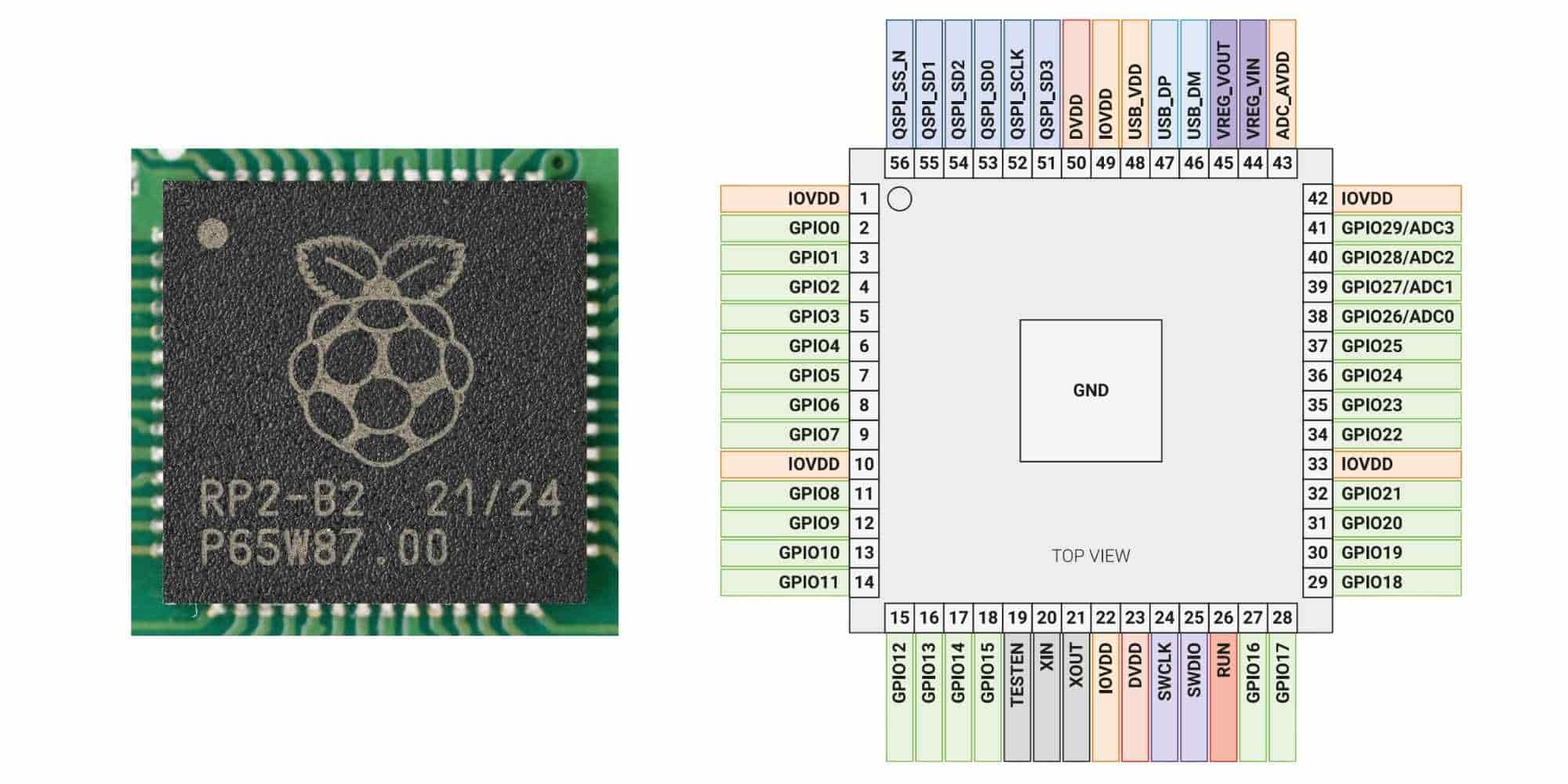
Looking at the chip pinout diagram, the RP2040 has 30 GPIO pins in total, numbered GPIO0 through GPIO29. These are the pins that let the chip interact with the outside world by reading or sending signals.
Four of these GPIO pins also double as analog input pins. From the pinout, GPIO26, GPIO27, GPIO28 and GPIO29 are labeled as ADC0 through ADC3, meaning they can read analog voltage values in addition to acting as regular digital pins.
The chip also has dedicated pins for specific communication interfaces. The QSPI pins are used exclusively for connecting external flash memory, which is how the chip loads and runs programs. There are also USB pins (USB_DP and USB_DM), power pins (IOVDD, DVDD, ADC_AVDD), and debug pins (SWCLK and SWDIO).
Implementation: From Zero to a Working Input-Output System
This week was my first time building an actual electronic circuit, I had never used a breadboard, never connected an LED physically, and never used a resistor outside of a textbook. On top of that, the last time I wrote any code was 12 years ago in school. So this week felt like restarting programming, but with hardware added to the mix. I decided to start as small as possible: make one LED blink.
Setting Up the XIAO RP2040
I connected the XIAO RP2040 to my MacBook using a USB-C cable and installed Arduino IDE. The setup was done by following the instructions from wiki.seeedstudio.com. There was one change though - on Mac, the Preferences is not under the File menu but under the Arduino IDE menu. I had a hard time figuring out the very first step but the rest were according to the website.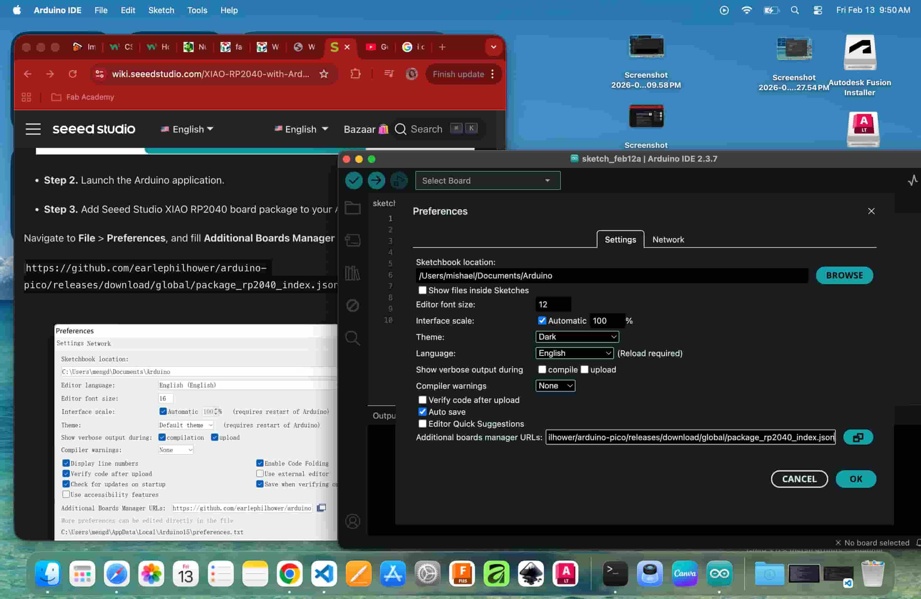
Toolchain / Board Manager Installation
Since the XIAO RP2040 is not supported by Arduino IDE out of the box, the correct board package needs to be installed manually. Here are the steps I followed:
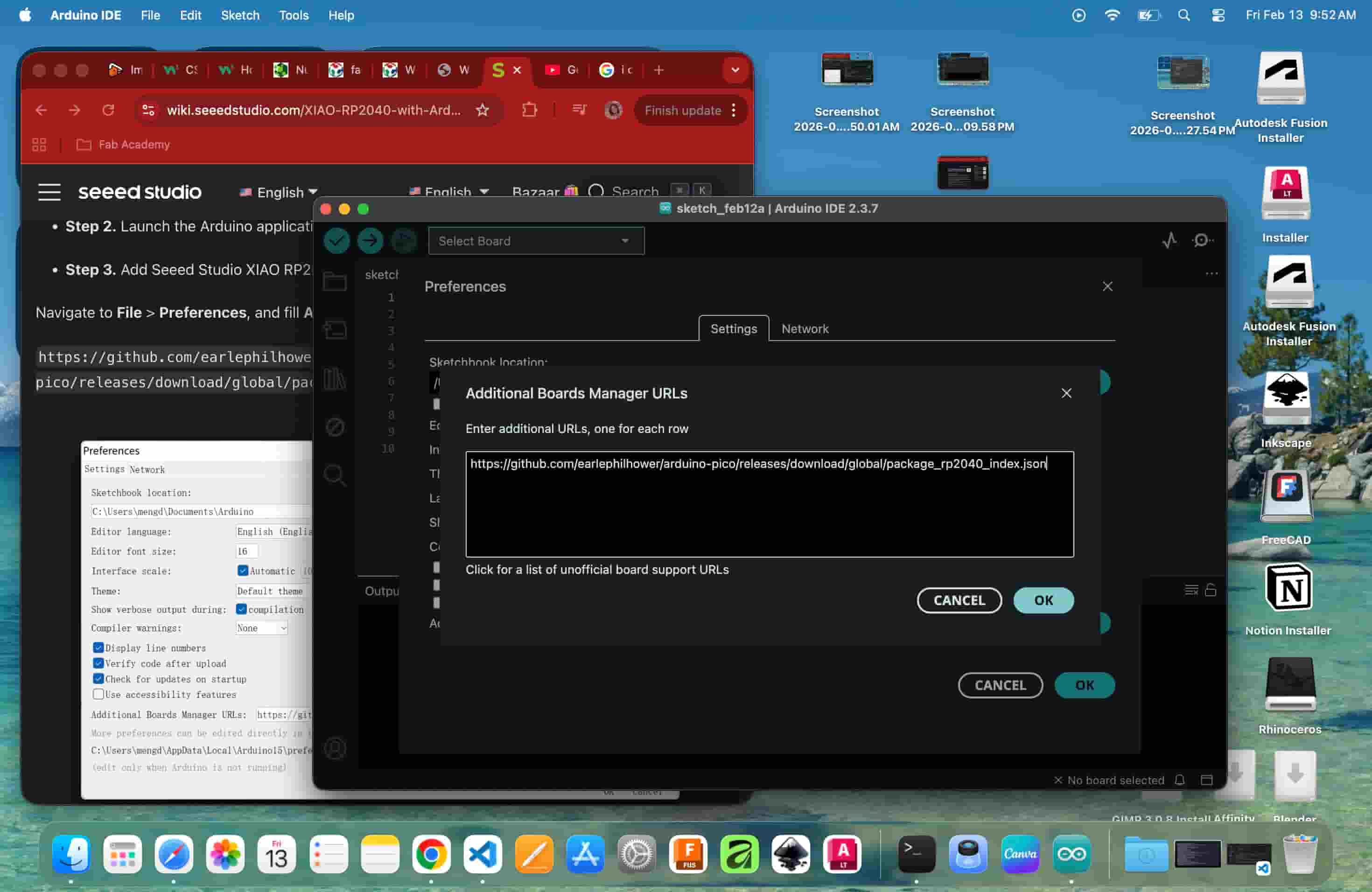
Step 1 - Add the Board Manager URL
Navigate to Arduino IDE > Preferences (on Mac). In the Additional Boards Manager URLs field, paste the following URL:
https://github.com/earlephilhower/arduino-pico/releases/download/global/package_rp2040_index.json
Click OK to save.
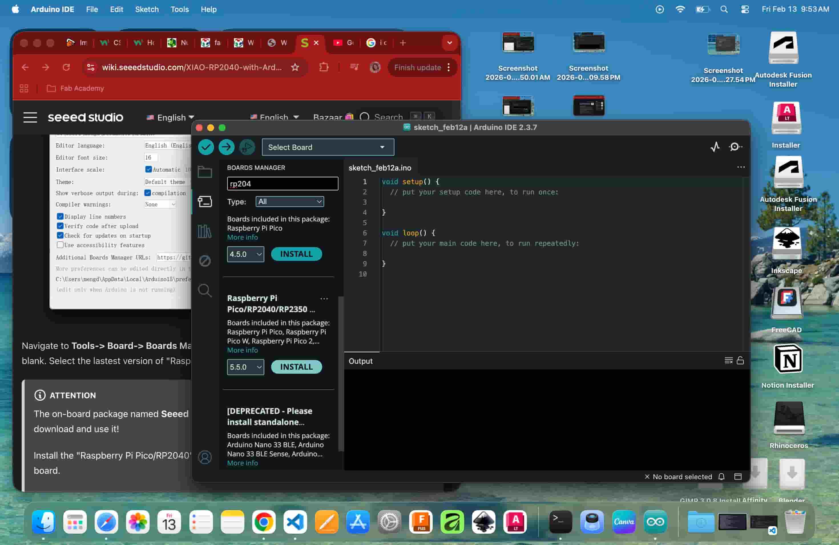
Step 2 - Open Boards Manager and Install the Package
Navigate to Tools > Board > Boards Manager. Search for rp2040. Two results appear, select Raspberry Pi Pico/RP2040/RP2350 (the standalone package, not the deprecated one) and install the latest version. The IDE will download and configure the toolchain components including pqt-openocd, pqt-picotool, and the platform files, all visible in the output panel.
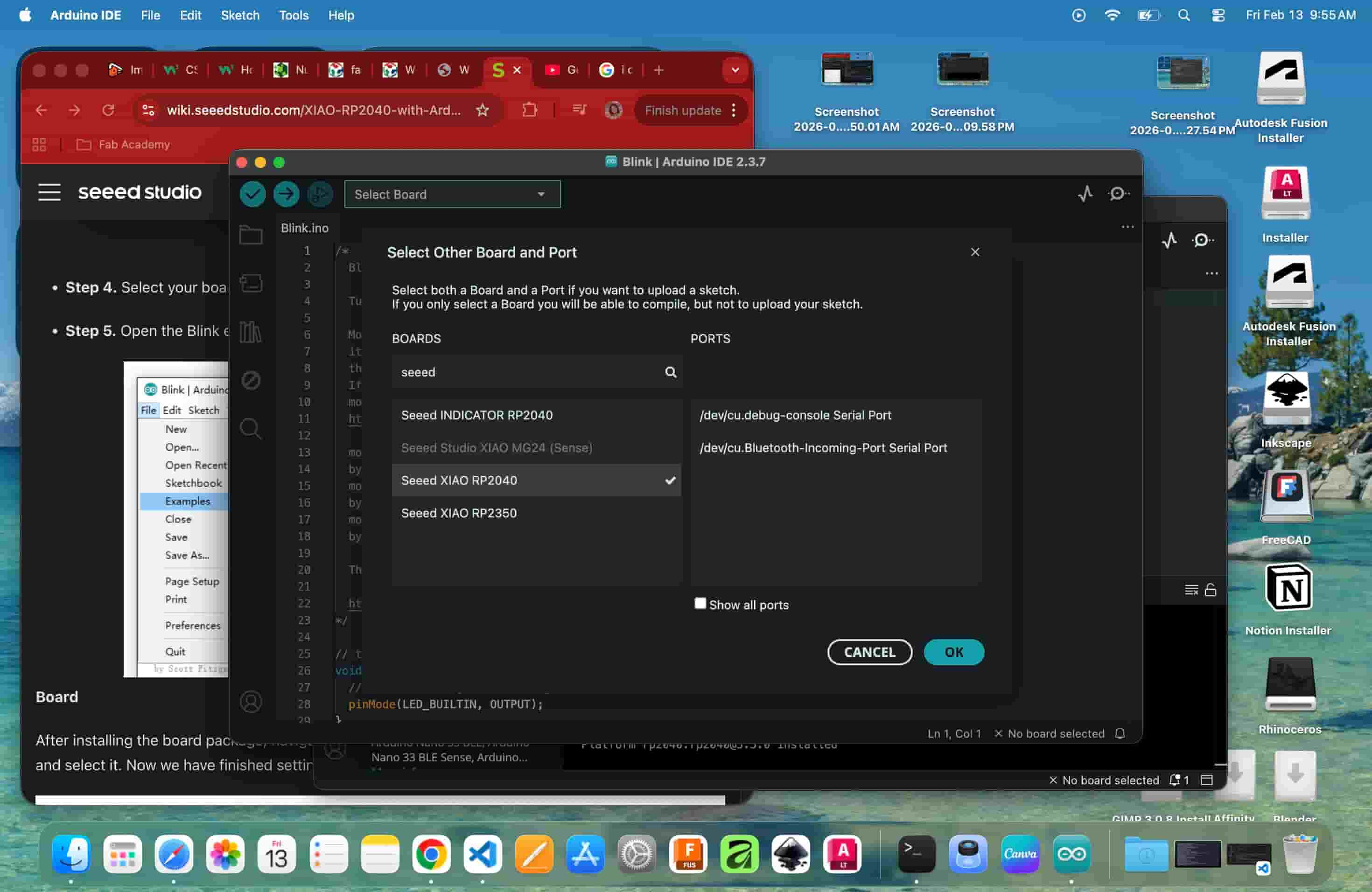
Step 3 - Select the XIAO RP2040 Board
Once installation is complete, go to Tools > Board > Select Other Board and Port. Search for seeed and select Seeed XIAO RP2040 from the list.
Step 4 - Select the Correct Port
In the same dialog, under Ports, select the appropriate serial port for your connected board.
First Programming
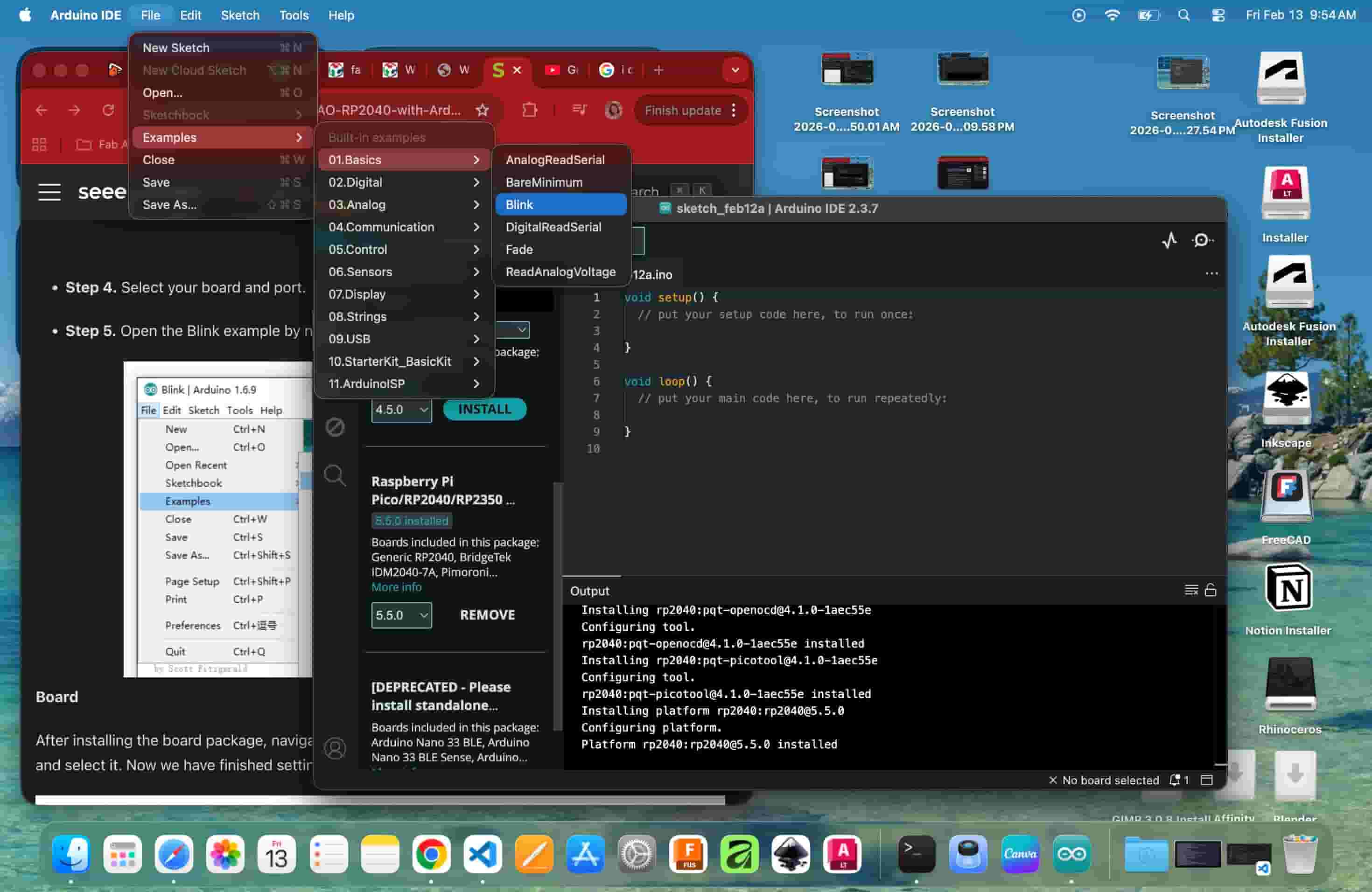
Uploading the Blink Sketch
I first tried the default Blink example via File > Examples > 01.Basics > Blink. It did not work. The example uses LED_BUILTIN, which does not directly map to the onboard LED pins of the XIAO RP2040. After checking the Pin Map from the wiki and datasheet, I defined the correct RGB LED pin manually:
#define USER_LED_R 17
#define USER_LED_R 17
// Defined USER_LED_R as 17th pin, USER_LED_G as 16 and USER_LED_B as 25 as per the pinmap for the model xiao rp2040
// the setup function runs once when you press reset or power the board
void setup() {
  // initialize digital pin LED_BUILTIN as an output.
  pinMode(USER_LED_R, OUTPUT);
  // Replaced LED_BUILTIN with USER_LED_R based on the board we are using
}

// the loop function runs over and over again forever
void loop() {
digitalWrite(USER_LED_R, LOW);   // turn the LED ON (active-LOW)
delay(1000);

digitalWrite(USER_LED_R, HIGH);  // turn the LED OFF
delay(1000);

}
Initial onboard LED Blink
That was the first moment I saw code create a physical result.
This code can create the blink but the other LEDs will be turned on too, so it was rewritten
#define USER_LED_R 17
#define USER_LED_G 16
#define USER_LED_B 25
// Defined RGB LED pins according to the XIAO RP2040 pin map

void setup() {
  // Configure RGB LED pins as output
  pinMode(USER_LED_R, OUTPUT);
  pinMode(USER_LED_G, OUTPUT);
  pinMode(USER_LED_B, OUTPUT);

  // Turn OFF green and blue channels (RGB LED is active LOW)
  digitalWrite(USER_LED_G, HIGH);
  digitalWrite(USER_LED_B, HIGH);
}

void loop() {
  // Blink red LED twice

  digitalWrite(USER_LED_R, LOW);   // ON (active LOW)
  delay(100);
  digitalWrite(USER_LED_R, HIGH);  // OFF
  delay(300);

  digitalWrite(USER_LED_R, LOW);   // ON
  delay(100);
  digitalWrite(USER_LED_R, HIGH);  // OFF
  delay(300);
}
Debugging: Unresponsive Board
When I uploaded the modified RGB LED code, the XIAO RP2040 showed no response. After examining it, my instructor identified a hardware fault with the unit and replaced it with a new one. The same code uploaded and ran correctly on the replacement, the red onboard LED blinked as expected, with the green and blue channels staying off.
Compiling Sketch
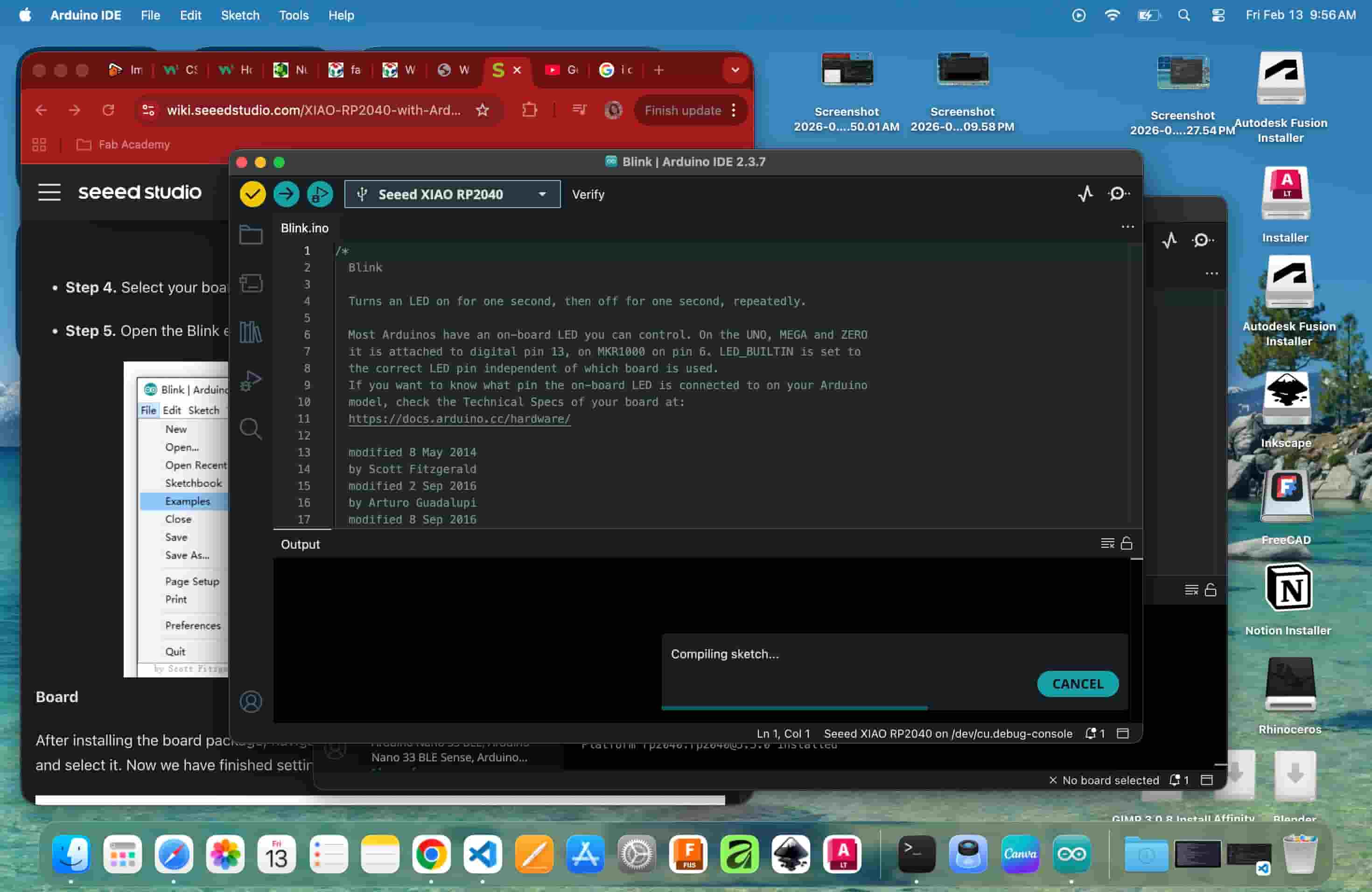
Clicking Verify compiles the sketch, it checks for errors and converts the code into binary that the microcontroller can run. Upload then flashes that binary to the board over USB.
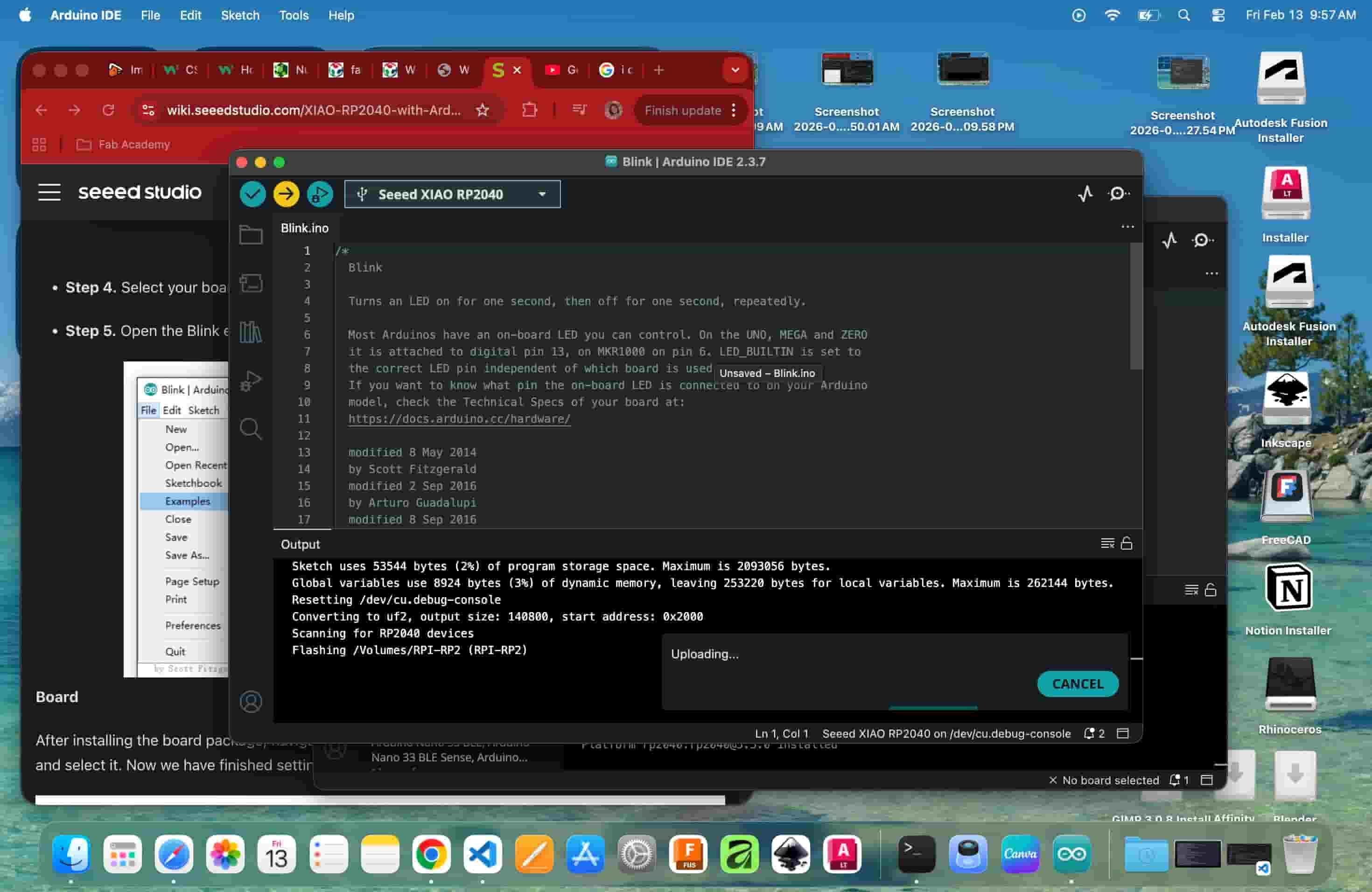
Uploading
Onboard LED Blink video
Understanding the Breadboard
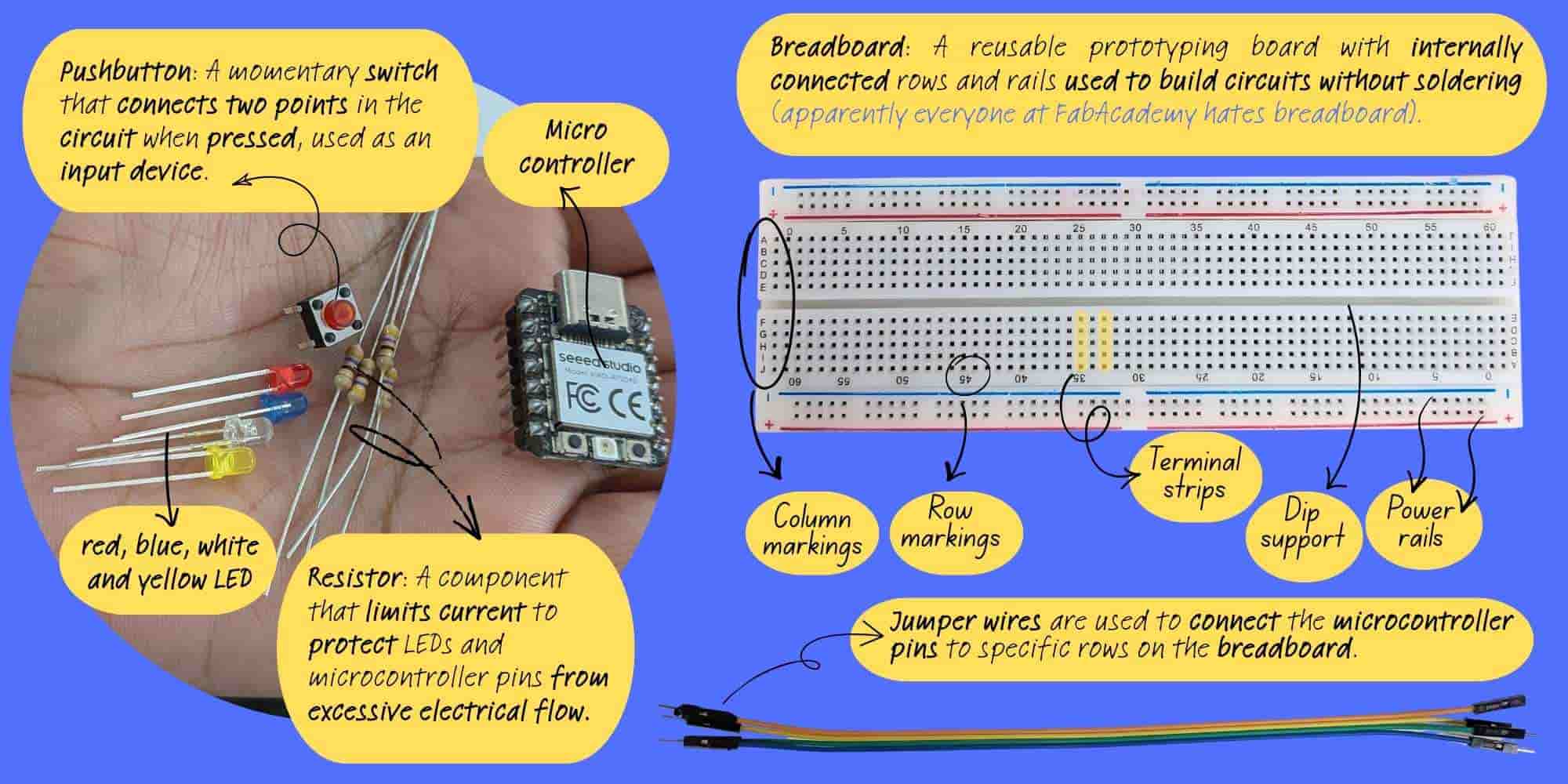
Before connecting external components, I had to understand how the breadboard works. At first it looked like random holes. But I learned:
Lighting My First External LED
Next, I connected a single external LED. I learned that an LED has:
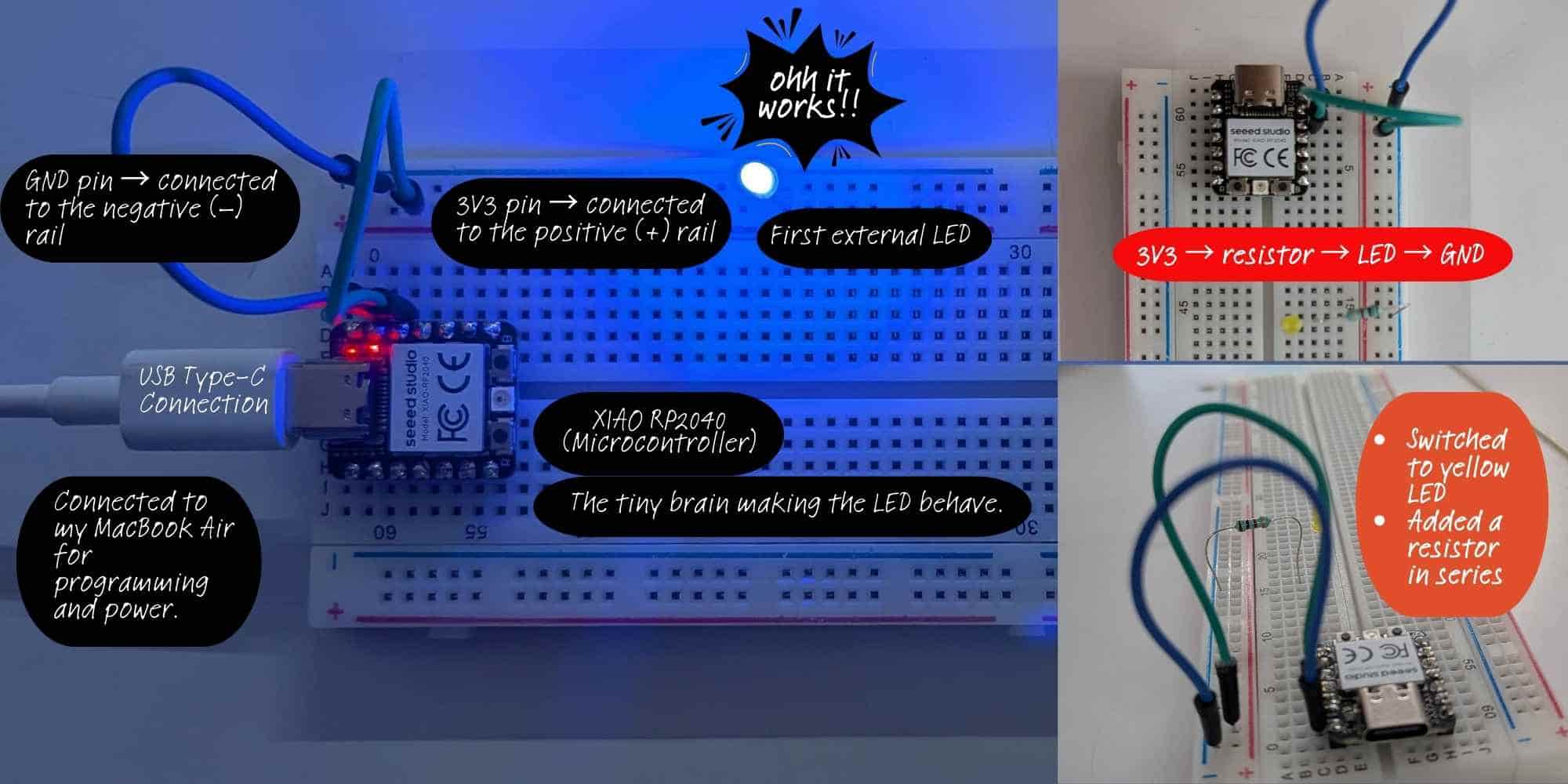
In this setup, I powered my first external LED directly using the 3V3 and GND pins of the XIAO RP2040.
#define YELLOW D7
// defined the external LED connected to D7 pin

// the setup function runs once when you press reset or power the board
void setup() {

  pinMode(YELLOW, OUTPUT);

}

// the loop function runs over and over again forever
void loop() {
  digitalWrite(YELLOW, HIGH);  // turn the LED on (HIGH is the voltage level)
  delay(500);
  digitalWrite(YELLOW, LOW);   // turn the LED off by making the voltage LOW
  delay(500);

  digitalWrite(YELLOW, HIGH);  // turn the LED on (HIGH is the voltage level)
  delay(500);
  digitalWrite(YELLOW, LOW);   // turn the LED off by making the voltage LOW
  delay(500);

}
Multiple LEDs and Chase Sequence (Output)
After successfully lighting one LED, I added two more LEDs:
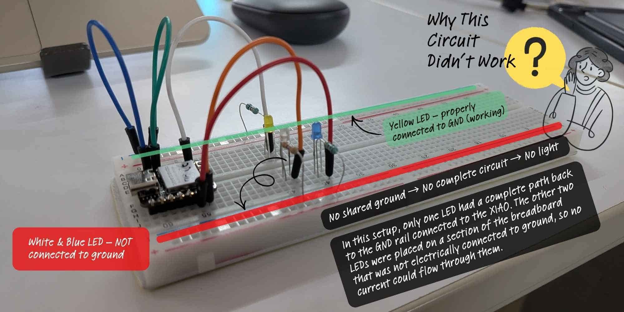
When I moved from lighting a single LED to connecting multiple LEDs for the chase sequence, I assumed I had wired everything correctly because each LED had its own resistor and was connected to a D pin. However, the circuit did not work as expected. The issue was not in the code, it was in the grounding. Only one LED had a proper connection back to the GND rail linked to the XIAO RP2040. The other LEDs were placed on a section of the breadboard that was not electrically connected to the ground line. Even though the wiring looked correct visually, the circuit was incomplete for two of the LEDs, so no current could flow through them. This mistake helped me understand that every component must share a common ground, and that breadboard power rails are not automatically connected across sections.
Once all negative legs were connected to the GND rail, I wrote a chase sequence using digitalWrite() and delay() so that one LED turned on at a time in a loop. This helped me understand timing and sequential output control.
#define YELLOW D7
#define WHITE D6
#define BLUE D5

// the setup function runs once when you press reset or power the board
void setup() {
  // initialize digital pin LED_BUILTIN as an output.
  pinMode(YELLOW, OUTPUT);
  pinMode(WHITE, OUTPUT);
  pinMode(BLUE, OUTPUT);

}

// the loop function runs over and over again forever
void loop() {
  digitalWrite(YELLOW, HIGH); // turn the LED on (HIGH is the voltage level)
  digitalWrite(WHITE, LOW);  // turn the LED off by making the voltage LOW
  digitalWrite(BLUE, LOW);  // turn the LED on (HIGH is the voltage level)
  delay(200);

  digitalWrite(YELLOW, LOW);
  digitalWrite(WHITE, HIGH);
  digitalWrite(BLUE, LOW);
  delay(200);

  digitalWrite(WHITE, LOW);
  digitalWrite(BLUE, HIGH);
  digitalWrite(YELLOW, LOW);
  delay(200);
}
Once I figured out the wiring, I then added one more LED and created a chase loop ina square arrangement
#define YELLOW D7
#define WHITE D6
#define BLUE D5
#define RED D8
#define time 100

// the setup function runs once when you press reset or power the board
void setup() {
  // initialize digital pin LED_BUILTIN as an output.
  pinMode(YELLOW, OUTPUT);
  pinMode(WHITE, OUTPUT);
  pinMode(BLUE, OUTPUT);
  pinMode(RED, OUTPUT);

}

// the loop function runs over and over again forever
void loop() {
  digitalWrite(YELLOW, HIGH);  // turn the LED on (HIGH is the voltage level)
  digitalWrite(WHITE, LOW);   // turn the LED off by making the voltage LOW
  digitalWrite(BLUE, LOW);  // turn the LED on (HIGH is the voltage level)
  digitalWrite(RED, LOW);  // turn the LED on (HIGH is the voltage level)
  delay(time);

  digitalWrite(YELLOW, LOW);
  digitalWrite(WHITE, HIGH);
  digitalWrite(BLUE, LOW);
  digitalWrite(RED, LOW);
  delay(time);

  digitalWrite(WHITE, LOW);
  digitalWrite(BLUE, HIGH);
  digitalWrite(YELLOW, LOW);
  digitalWrite(RED, LOW);
  delay(time);

  digitalWrite(WHITE, LOW);
  digitalWrite(BLUE, LOW);
  digitalWrite(RED, HIGH);
  digitalWrite(YELLOW, LOW);

  delay(time);
}
Hero Shot
Embedded System
Adding a Push Button for LED Chase (Input & Output Devices)
After working with outputs, I wanted to understand input. I added a push button to the breadboard. The button has four legs but internally works as a switch connecting two sides when pressed. In code:
pinMode(BUTTON, INPUT_PULLDOWN);
Inside loop(), I used:
if (digitalRead(BUTTON) == HIGH)
This was my first complete system combining:
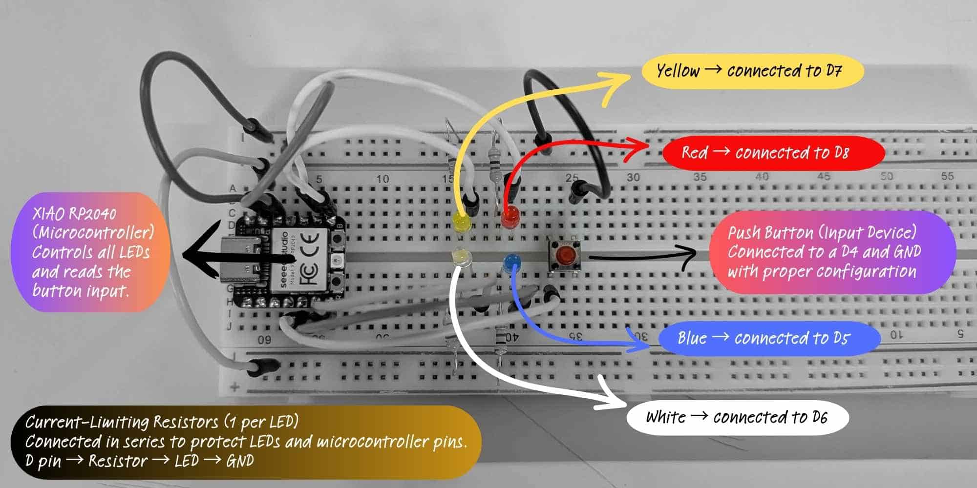
This is the completed circuit after correcting grounding issues. Each LED (yellow, white, blue, red) is connected to a separate D pin on the XIAO RP2040, with an individual current-limiting resistor connected in series. All LEDs share a common ground rail connected to the XIAO’s GND pin. The push button is connected to D4 and GND and configured as an input device in the program. When pressed, it triggers the LED chase sequence. This setup represents a complete input-output embedded system:
#define YELLOW D7
#define WHITE D6
#define BLUE D5
#define RED D8
#define time 100
#define BUTTON D4

// the setup function runs once when you press reset or power the board
void setup() {
  // initialize digital pin LED_BUILTIN as an output.
  pinMode(YELLOW, OUTPUT);
  pinMode(WHITE, OUTPUT);
  pinMode(BLUE, OUTPUT);
  pinMode(RED, OUTPUT);
  pinMode(BUTTON, INPUT_PULLDOWN);

}

// the loop function runs over and over again forever
void loop() {

if (digitalRead(BUTTON)==HIGH) {
  chase_4();
  //Made a separate function chase_4 to better organize
  //To set the condition: if pulldown is used, set the condition to high. if pullup is used, set it to low
}
else
{
  digitalWrite(YELLOW, LOW);  // turn the LED on (HIGH is the voltage level)
  digitalWrite(WHITE, LOW);  // turn the LED off by making the voltage LOW
  digitalWrite(BLUE, LOW);  // turn the LED on (HIGH is the voltage level)
  digitalWrite(RED, LOW);  // turn the LED on (HIGH is the voltage level)

}

}

// to run the leds as a ring
void chase_4()
{

  digitalWrite(YELLOW, HIGH);
  digitalWrite(WHITE, LOW);
  digitalWrite(BLUE, LOW);
  digitalWrite(RED, LOW);
  delay(time);

  digitalWrite(YELLOW, LOW);
  digitalWrite(WHITE, HIGH);
  digitalWrite(BLUE, LOW);
  digitalWrite(RED, LOW);
  delay(time);

  digitalWrite(WHITE, LOW);
  digitalWrite(BLUE, HIGH);
  digitalWrite(YELLOW, LOW);
  digitalWrite(RED, LOW);
  delay(time);

  digitalWrite(WHITE, LOW);
  digitalWrite(RED, HIGH);
  digitalWrite(BLUE, LOW);
  digitalWrite(YELLOW, LOW);
  delay(time);
}
Learning to use For Loop
During Asia Regional review, Rico told me to use the for loop function to cleanup my button chase code. So I tried learning to do that. I tried chasing diagonal this time, for this I just had to change the order of leds. I used a for loop to control the LEDs sequentially instead of writing repeated code for each one.
Prompt used to generate the code on ChatGPT:
Convert my Arduino LED chase code (written with repeated digitalWrite) into a version using a for loop + array. Keep the same behavior.
Integer and Array Declaration
The code uses int to store whole numbers, including the LED pin numbers.
int leds[] = {YELLOW, BLUE, WHITE, RED};
int numLeds = 4;
The array leds[] groups all LED pins into one list.
Each LED gets an index number (0–3), which allows the for loop to access them one by one.
The variable numLeds stores the total number of LEDs, making the code easier to modify later.
for (int i = 0; i < numLeds; i++)
{
  digitalWrite(leds[i], HIGH);
  delay(time);
  digitalWrite(leds[i], LOW);
}
The loop starts with i = 0 and increases i by 1 each time (i++) until it reaches the total number of LEDs.
Since the LEDs are stored in an array, the loop automatically selects each LED one by one and turns it ON and OFF.
This makes the code shorter, cleaner, and easier to modify.
// Define names for each LED pin
#define YELLOW D9
#define BLUE   D8
#define WHITE  D6
#define RED    D5

// Define button pin
#define BUTTON D7

// Time delay between LED changes (in milliseconds)
#define time   100

// Store all LED pins inside an array
// This lets us control them using a loop
int leds[] = {YELLOW, WHITE, BLUE, RED};

// Total number of LEDs in the array
int numLeds = 4;

void setup() {

  // Set all LED pins as OUTPUT (they send voltage out)
  pinMode(YELLOW, OUTPUT);
  pinMode(WHITE, OUTPUT);
  pinMode(BLUE, OUTPUT);
  pinMode(RED, OUTPUT);

  // Set button as INPUT with internal pulldown resistor
  // When pressed, reads HIGH
  // When not pressed, reads LOW
  pinMode(BUTTON, INPUT_PULLDOWN);
}

void loop() {

  // Check if button is pressed
  if (digitalRead(BUTTON) == HIGH) {

    // If pressed, run LED chase pattern
    chase_4();
  }
  else {

    // If not pressed, turn all LEDs OFF
    // Loop goes through each LED one by one
    for (int i = 0; i < numLeds; i++) {

      // leds[i] selects LED number 0,1,2,3
      digitalWrite(leds[i], LOW);
    }
  }
}

// Function to run LEDs one after another
void chase_4() {

  // Loop through each LED
  for (int i = 0; i < numLeds; i++) {

    // Turn current LED ON
    digitalWrite(leds[i], HIGH);

    // Wait for defined time
    delay(time);

    // Turn current LED OFF before moving to next
    digitalWrite(leds[i], LOW);
  }
}
Reflection
After completing my first embedded system and understanding how the blink and chase sequences worked, something unexpected happened. On my way home that evening, I couldn’t stop noticing all the blinking lights around me, on trucks, buses, traffic signals, signboards, and vehicles on the road. It felt like someone had opened a door in my head that had been locked for 30 years. Although I have always been fascinated by lights like anyone else, I had never thought about them from this perspective. Now I found myself observing the exact timing of blink sequences on vehicles and wondering what kind of code would produce that delay, that rhythm, that pattern. For the first time, I was not just seeing lights, I was seeing logic running inside them.
Embedded Programming: Button-Controlled Serial Output
Continuous Output vs State Change Detection
Initially, I used a simple condition:
if (digitalRead(BUTTON) == LOW) {
  Serial.println("OUCH");
  delay(200);
}
In this version, the message prints continuously while the button is being held down. Since the loop() function runs repeatedly, the condition remains true as long as the button is pressed, resulting in:
OUCH
OUCH
OUCH
OUCH
This method checks the current level of the button (LOW or HIGH).
Later, I implemented state change detection.
In this exercise, I programmed a push button connected to pin D7 to print a message in the Serial Monitor when everytime the button is pressed.
Prompt used on ChatGPT for the code:
Arduino code: detect button press using edge detection (INPUT_PULLUP) and print a message once per press.
#define BUTTON D7

int lastState = HIGH;

void setup() {
  pinMode(BUTTON, INPUT_PULLUP);
  Serial.begin(9600);
}

void loop() {

  int currentState = digitalRead(BUTTON);

  if (lastState == HIGH && currentState == LOW) {
    Serial.println("Ouch, that hurts!");
  }

  lastState = currentState;
}
Hero Shot
Explanation
The button is configured using INPUT_PULLUP, which activates the microcontroller’s internal pull-up resistor. This means:
To avoid printing continuously while the button is held down, I used a state change detection method. The variable lastState stores the previous reading of the button. The variable currentState stores the current reading.
The program checks for a transition from HIGH to LOW, which indicates that the button has just been pressed:
if (lastState == HIGH && currentState == LOW)
When this transition occurs, the message:
Ouch, that hurts!
is printed once.
Finally, lastState is updated at the end of each loop cycle so the program can compare values during the next iteration.
Reflection
This activity looked simple at first, but I spent more time debugging than expected. I learned that even if the code is correct, wrong wiring can completely change the result. Fixing the button orientation and understanding how INPUT_PULLUP works helped me understand the connection between hardware and software more clearly. I also learned how to detect a button press properly instead of printing continuously. This exercise made me more patient while debugging and more confident working with physical components.
Button-Controlled LED Blinking with Toggle Function
Prompt used on ChatGPT to generate the code:
Write Arduino code where a button toggles LED blinking ON and OFF.
Requirements:
LED on D8, button on D7 using INPUT_PULLDOWN
Each press toggles blinking (not hold)
Use proper button press detection (no repeated triggering)
Make LED blink every 500 ms using millis() (avoid delay for timing)
Add simple debounce
This program uses a push button to toggle an LED blinking mode on and off. When the button is pressed, the system detects a rising edge (LOW to HIGH) and switches the blinking state. Each press alternates between enabling and disabling the LED blinking.
The variable blinking controls whether the LED should blink. Instead of using delay() for timing, the program uses millis() to create a non-blocking 500 ms interval. This allows the system to continuously check the button state while managing the LED timing simultaneously.
Key concepts demonstrated:
#define LED_PIN D8
#define BUTTON_PIN D7

bool blinking = false;
bool lastButtonState = LOW;   // Default state is LOW with pull-down
bool ledState = LOW;

unsigned long previousMillis = 0;
const long interval = 500;

void setup() {
  pinMode(LED_PIN, OUTPUT);
  pinMode(BUTTON_PIN, INPUT_PULLDOWN);  // Internal pull-down enabled

  Serial.begin(9600);
}

void loop() {

  bool currentButtonState = digitalRead(BUTTON_PIN);

  // Detect rising edge (LOW → HIGH)
  if (lastButtonState == LOW && currentButtonState == HIGH) {

    blinking = !blinking;   // Toggle blinking mode

    if (blinking) {
      Serial.println("LED Blinking: ON");
    } else {
      Serial.println("LED Blinking: OFF");
      digitalWrite(LED_PIN, LOW);
      ledState = LOW;
    }

    delay(50); // debounce
  }

  lastButtonState = currentButtonState;

  if (blinking) {
    unsigned long currentMillis = millis();

    if (currentMillis - previousMillis >= interval) {
      previousMillis = currentMillis;

      ledState = !ledState;
      digitalWrite(LED_PIN, ledState);
    }
  }
}
Seeed Studio XIAO RP2040 with MicroPython
Introduction to MicroPython
MicroPython is a version of Python made for microcontrollers. It allows us to write simple Python code and run it directly on small boards like the Seeed Studio XIAO RP2040.
Toolchain Setup
To program the board, I needed an editor that supports MicroPython. For this, I downloaded Thonny IDE.
After installing and opening Thonny, I first configured the interpreter. I went to Tools → Options → Interpreter and selected MicroPython (Raspberry Pi Pico) as the interpreter, with the port set to “Try to detect automatically.” This step told Thonny that I was working with a MicroPython-based RP2040 board.
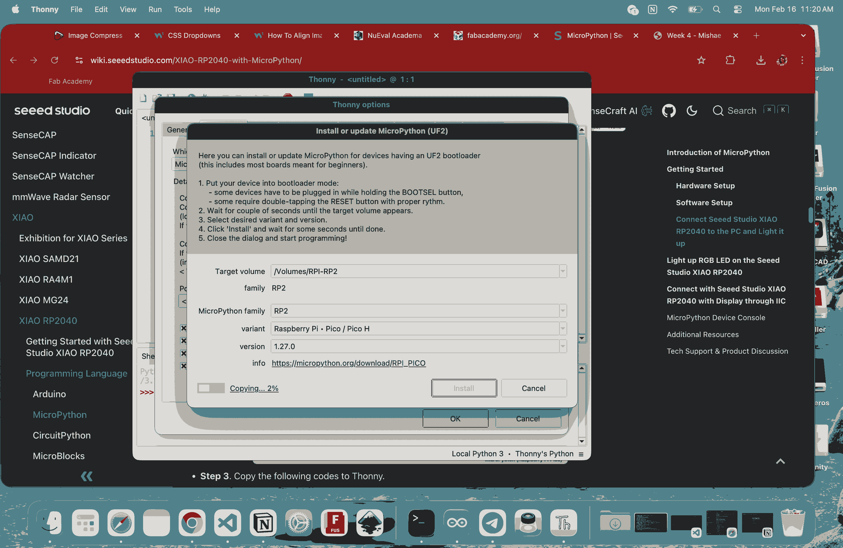
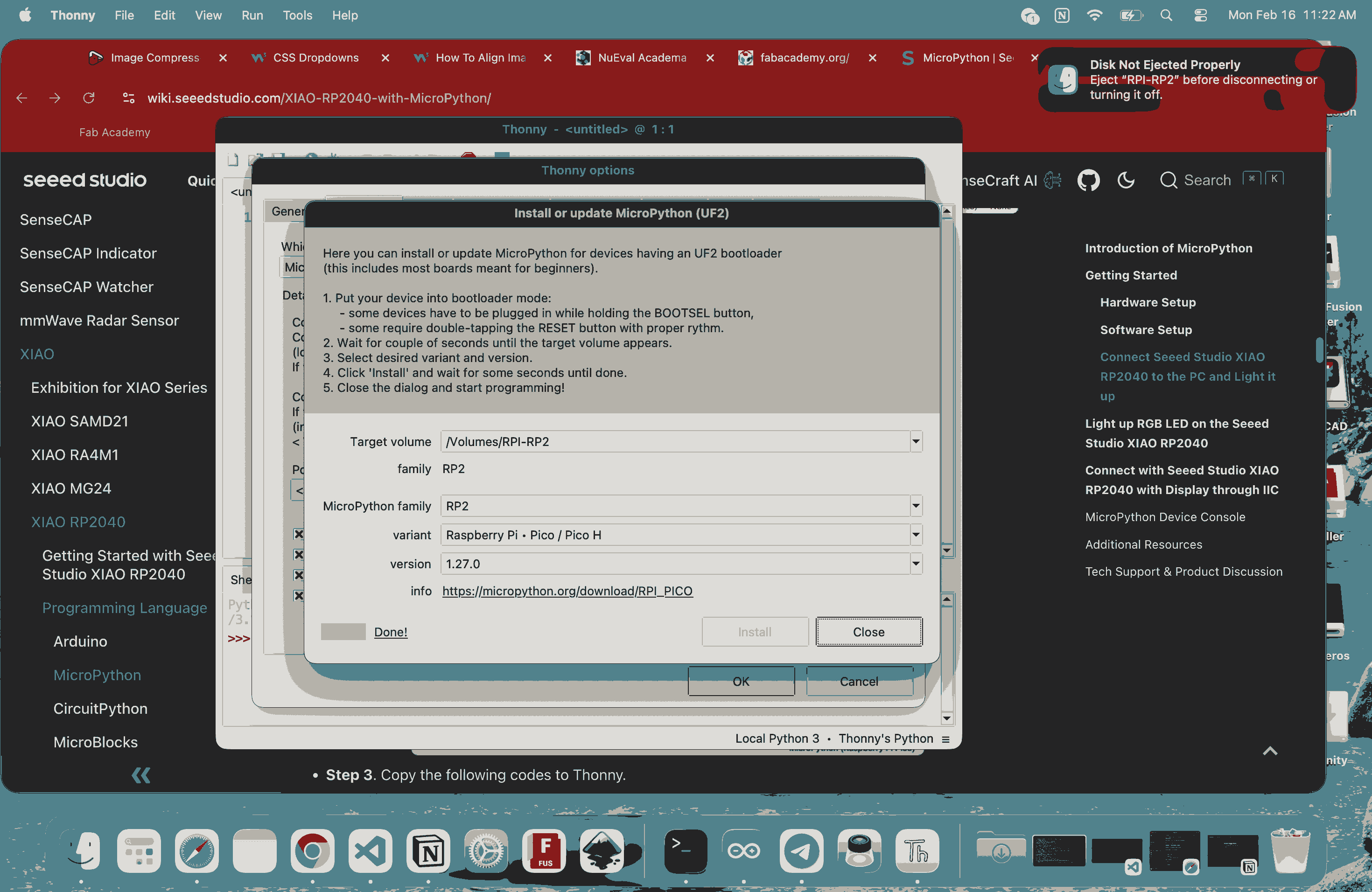
Next, I installed the MicroPython firmware onto the board. To do this, I pressed and held the BOOT button on the XIAO RP2040 and connected it to my computer. The board appeared as an RPI-RP2 drive. In Thonny, I clicked on “Install or Update MicroPython,” kept the default version, and clicked Install. This successfully flashed the MicroPython firmware onto the board.
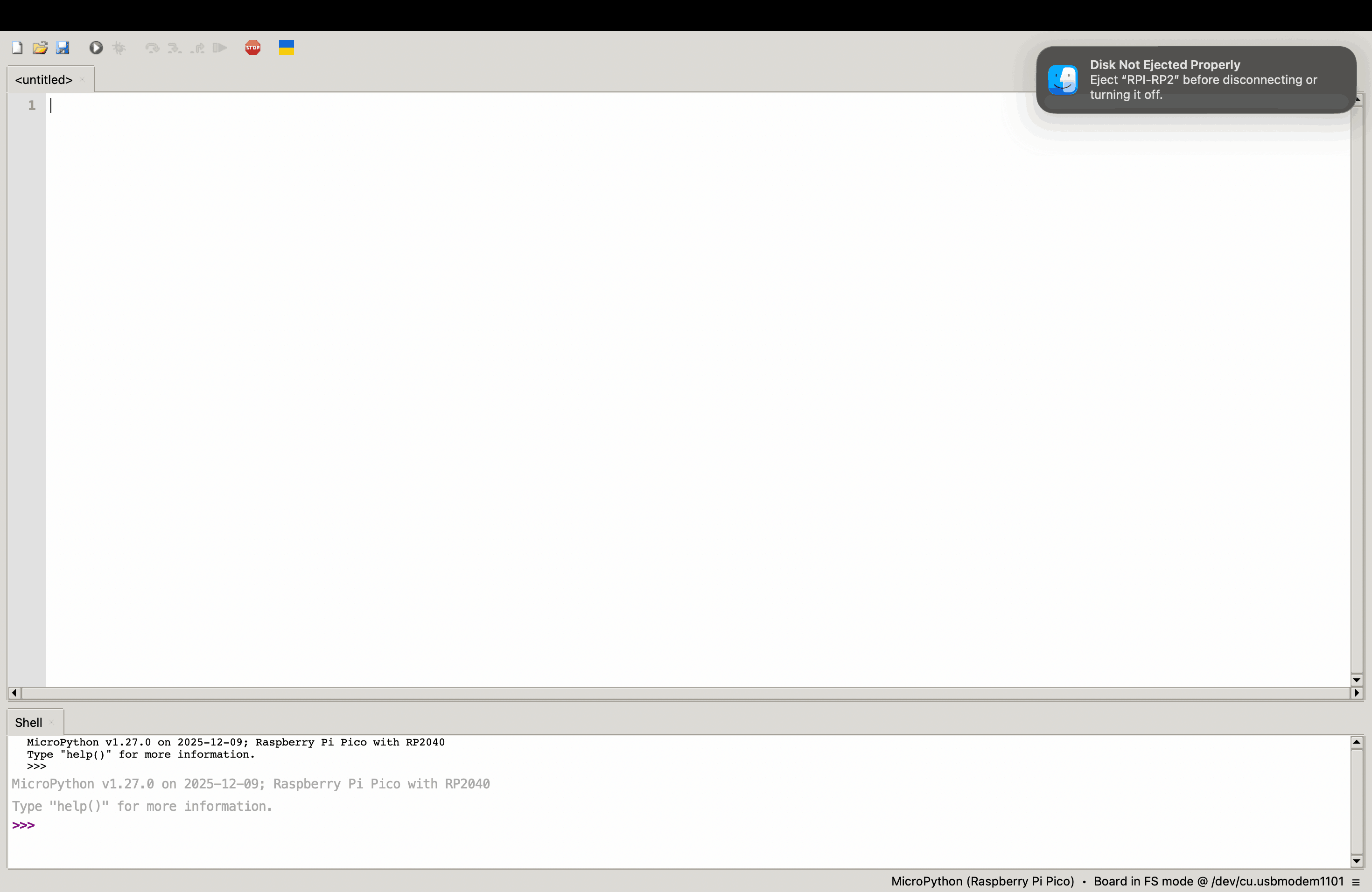
After the firmware installation, I used the simple LED blinking test program from wiki seeed studio in Thonny and clicked Run. When prompted, I saved the file either to “This Computer” or directly to “Raspberry Pi Pico.” Once executed, the onboard LED started blinking and the counter value printed in the Shell. This confirmed that the board was properly connected, the firmware was correctly installed, and the toolchain was functioning as expected.
from machine import Pin, Timer

led = Pin(25, Pin.OUT)
Counter = 0
Fun_Num = 0

def fun(tim):
    global Counter
    Counter = Counter + 1
    print(Counter)
    led.value(Counter%2)

tim = Timer(-1)
tim.init(period=1000, mode=Timer.PERIODIC, callback=fun)
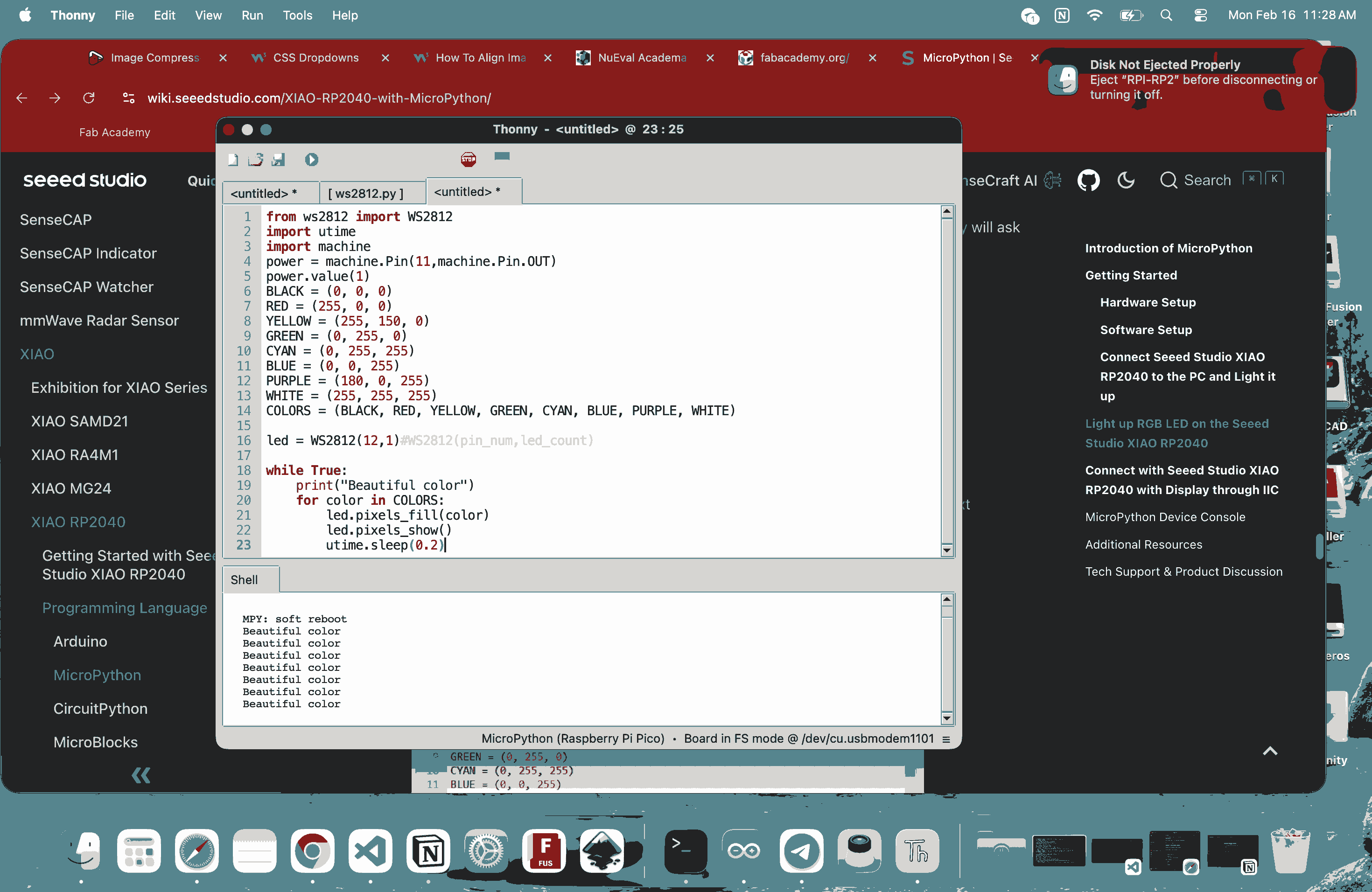
To control the RGB LED, I added an external library. I downloaded the ws2812.py file, opened it in Thonny, and saved it directly to the Raspberry Pi Pico. I made sure the file name was exactly ws2812.py, since any change in the name would prevent it from working. After that, I used the code from wiki seeed studio for the RGB LED program and ran it. The LED cycled through different colors, and the corresponding output was visible in the Shell.
from ws2812 import WS2812
import utime
import machine
power = machine.Pin(11,machine.Pin.OUT)
power.value(1)
BLACK = (0, 0, 0)
RED = (255, 0, 0)
YELLOW = (255, 150, 0)
GREEN = (0, 255, 0)
CYAN = (0, 255, 255)
BLUE = (0, 0, 255)
PURPLE = (180, 0, 255)
WHITE = (255, 255, 255)
COLORS = (BLACK, RED, YELLOW, GREEN, CYAN, BLUE, PURPLE, WHITE)

led = WS2812(12,1)#WS2812(pin_num,led_count)

while True:
    print("Beautiful color")
    for color in COLORS:
        led.pixels_fill(color)
        led.pixels_show()
        utime.sleep(0.2)
Overall, my workflow was straightforward: I downloaded and installed Thonny IDE, used it to install the MicroPython firmware on the XIAO RP2040, and then uploaded and ran the sample codes provided on the Seeed Studio wiki page for setting up Thonny with the XIAO RP2040. I did not write the programs myself at this stage; I used the official example codes to test the setup. I monitored the output through Thonny’s Shell and added the required external library directly to the board. This process confirmed that the board was properly configured and ready for programming using MicroPython.
Reflection
This week was important because it forced me to connect programming with physical systems. I realized that every line of code directly controls voltage on a real pin, HIGH and LOW are actual electrical states, not abstract values. Hardware does not forgive mistakes: wrong wiring, missing resistors, or incorrect pin numbers immediately cause failure. Unlike screen-based programming, both logic and physical connections must work together. I also worked with two different toolchains. One was the Arduino-based workflow, where code is compiled and uploaded as firmware. The other was the MicroPython workflow using Thonny, where I installed firmware separately and then ran scripts directly on the board. Arduino felt more rigid and structured, while MicroPython felt more interactive because I could run and test code quickly through the Shell. For the MicroPython setup, I used the official sample codes from the Seeed Studio wiki to verify that everything was working. I began the week unsure and slightly overwhelmed. By the end, I had