Week 2: Introduction to 2D & 3D Tools
Assignment
Model (raster, vector, 2D, 3D, render, animate, simulate, ...) a possible final project, compress your images and videos, and post a description with your design files on your class page
This week began with a brief introduction to various 2D and 3D softwares, which was honestly a lot to take in. I do have previous experience with Adobe Creative Suite, Rhino, and SketchUp; therefore, things made sense. However, the challenge was to use the open-source ones and create or model projects from scratch. Inkscape, Photopea, and Affinity were easy to adapt to, but Fusion 360 and Blender gave me a mini panic attack. Our instructors for this week were Mufeed, Namita and Akash.
Rastor & Vector

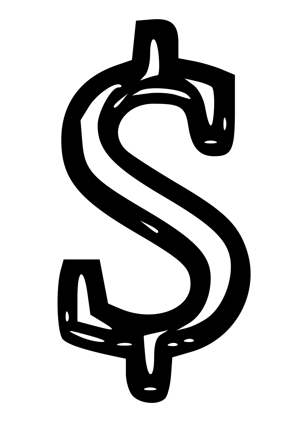
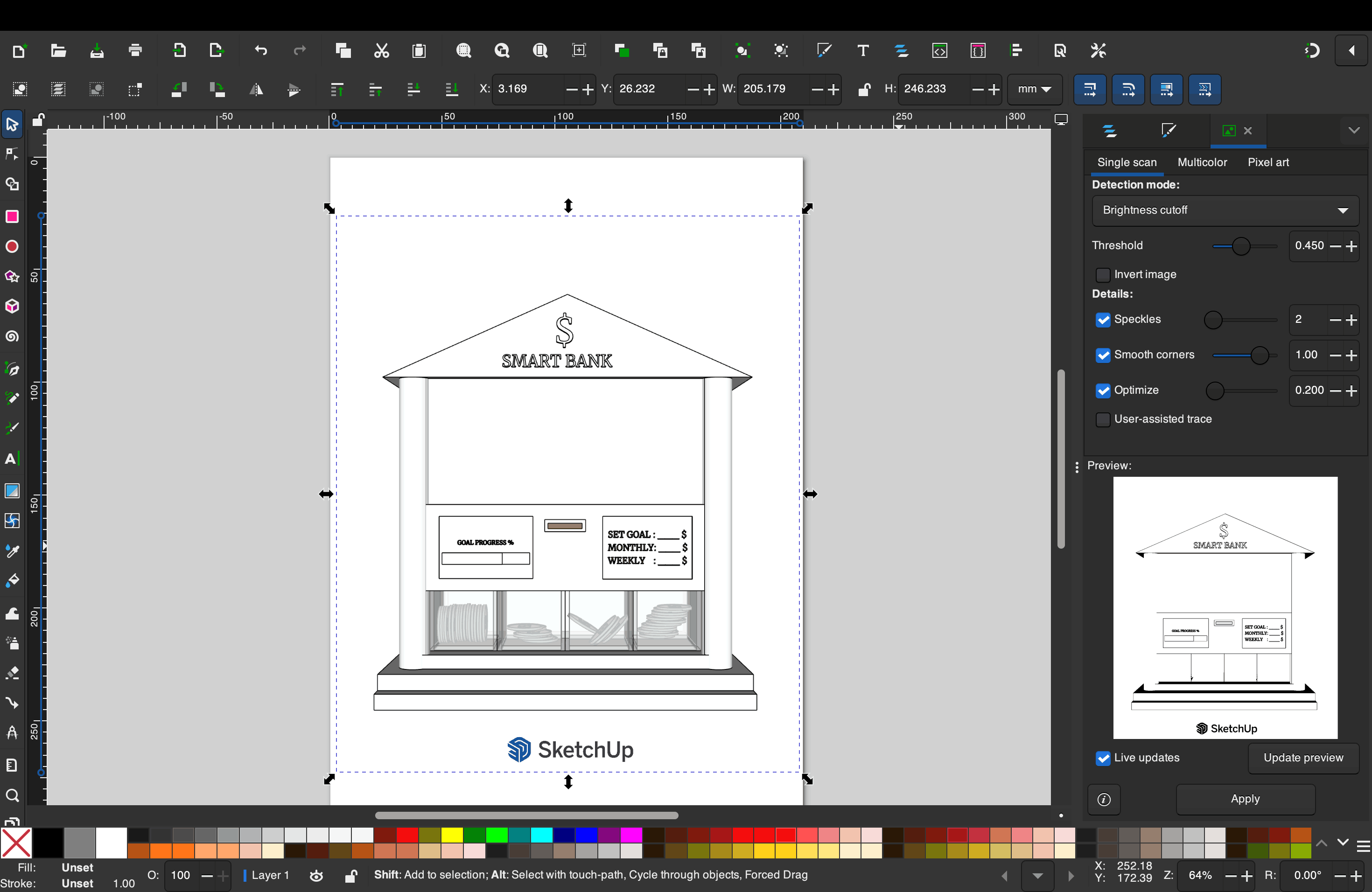
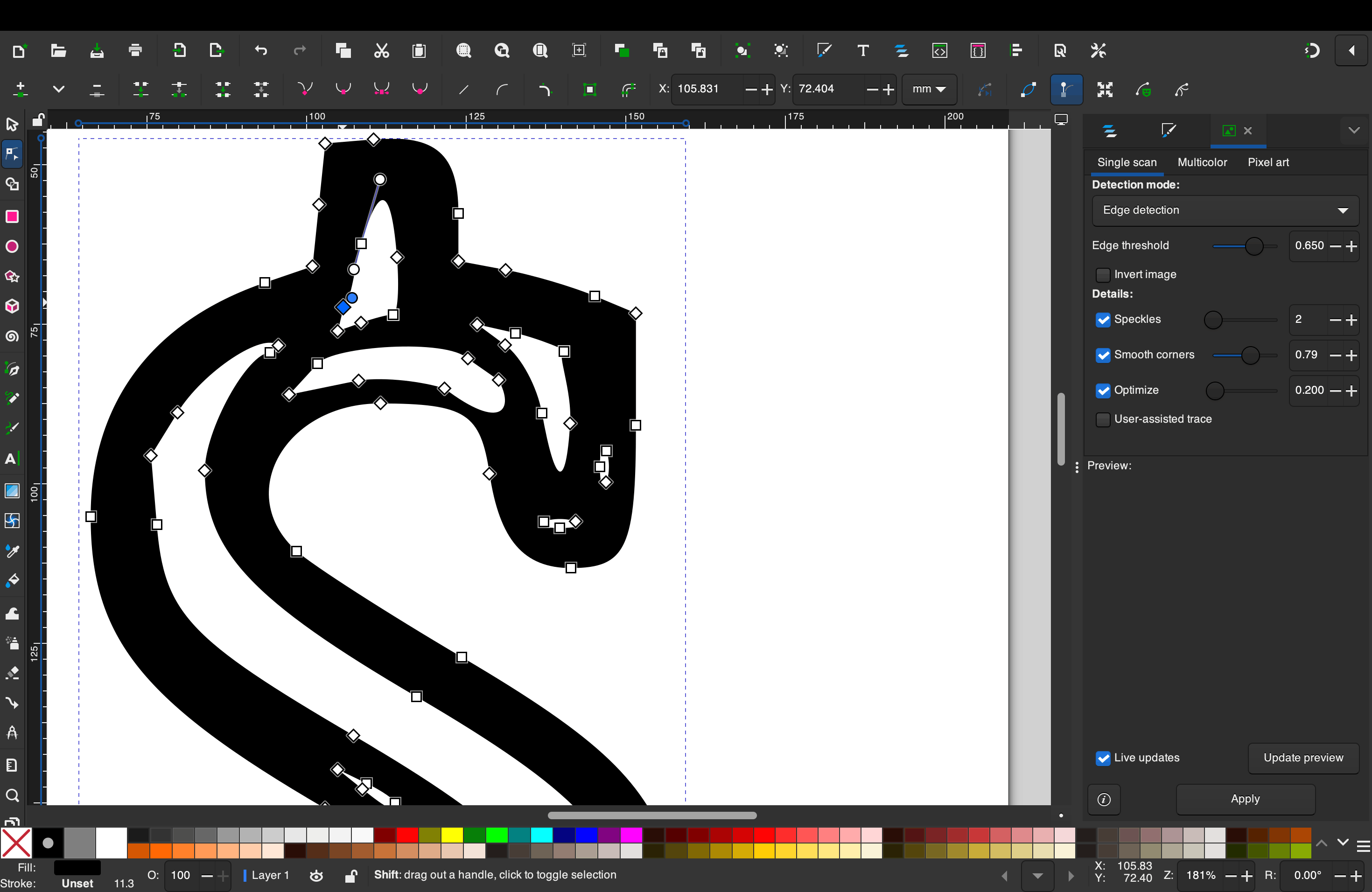
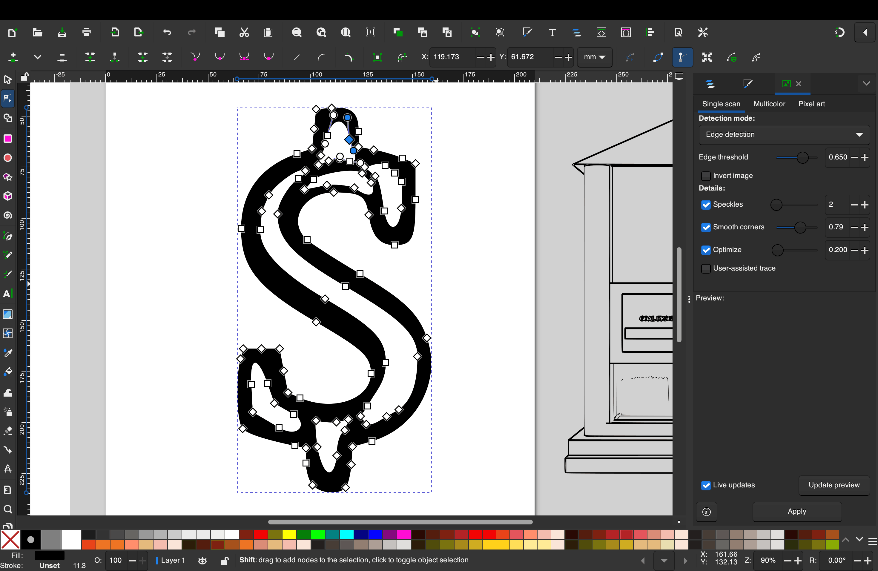
The screenshot I took from the SketchUp model was a raster image, meaning it was made up of pixels. Because of this, when the image was zoomed in, the edges of the dollar sign appeared blurry and pixelated, as the resolution was fixed. This worked fine for reference, but it limited how much I could scale or modify the image without losing quality. After importing this raster image into Inkscape, I used the bitmap tracing option to convert it into a vector. Unlike raster images, vector files are made using paths and mathematical points rather than pixels, which allows them to be scaled infinitely without any loss of clarity. Once the dollar sign was converted into a vector, I was able to clean up the edges and manipulate its shape more freely to suit my design needs. This step helped me better understand the advantage of working with vectors, especially when refining details or preparing graphics for different outputs.
Inkscape
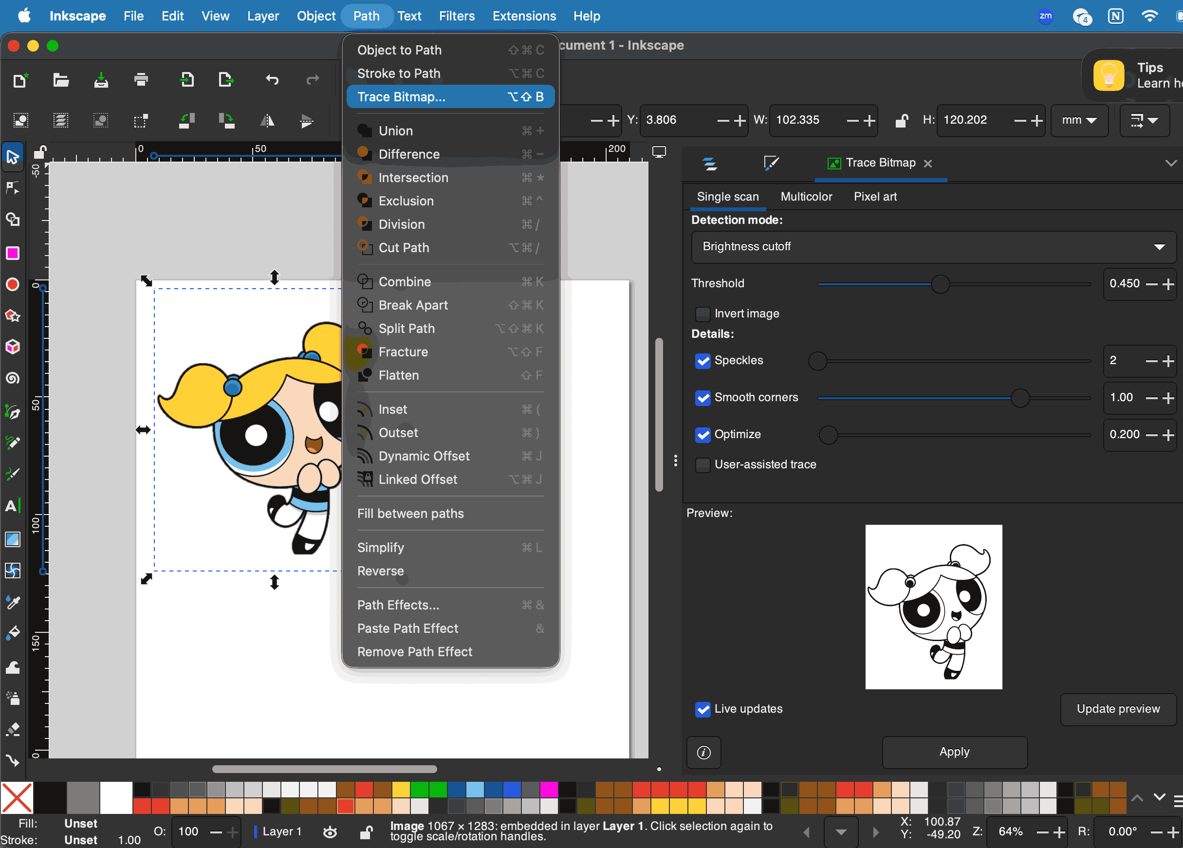
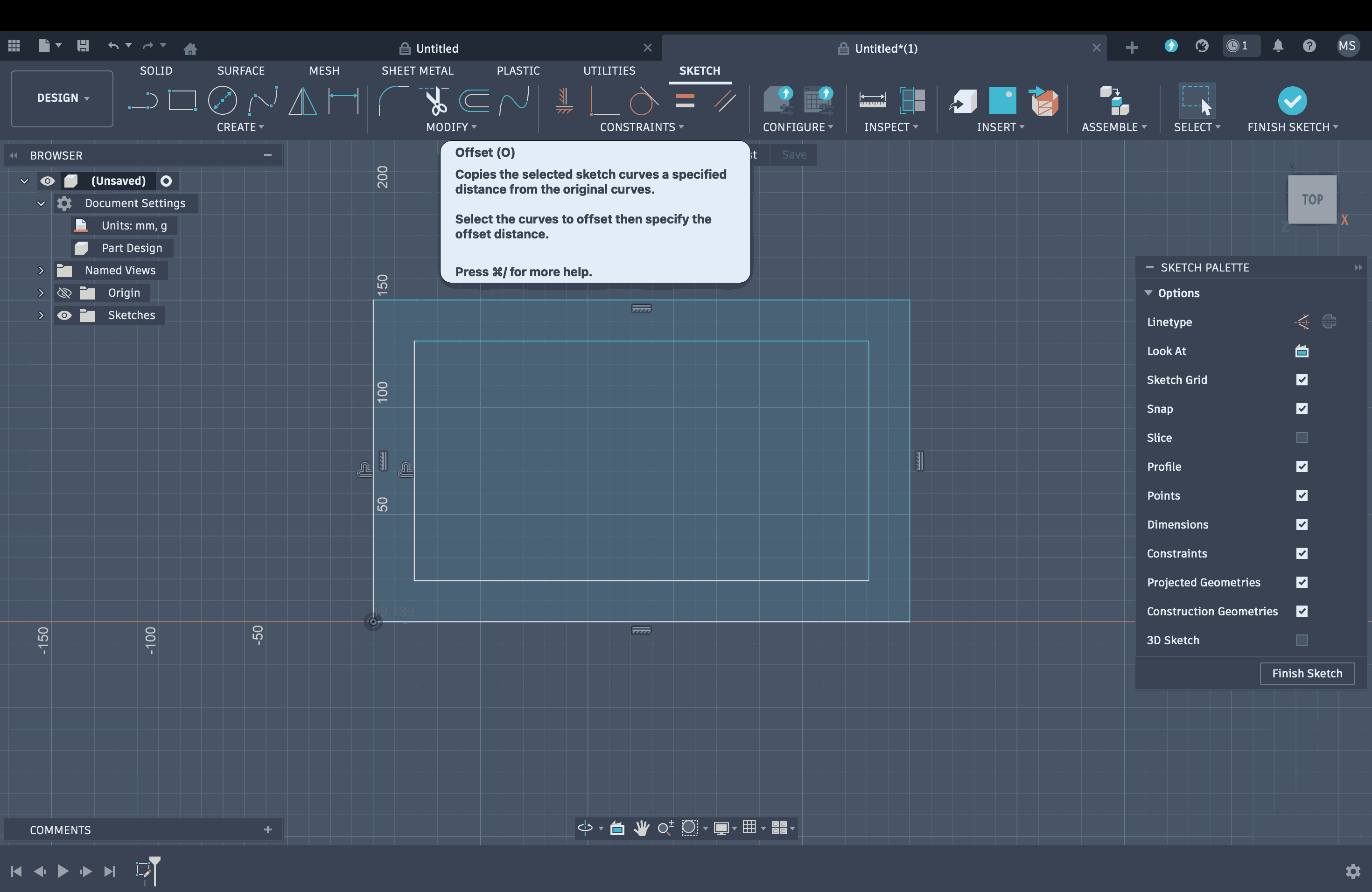
Inkscape is a free, open-source vector graphics editor, primarily using the Scalable Vector Graphics (SVG) format. It creates images based on mathematical formulas (paths, curves, shapes) rather than pixels, allowing for infinite scaling without quality loss. It is ideal for logos, icons, and technical illustrations.
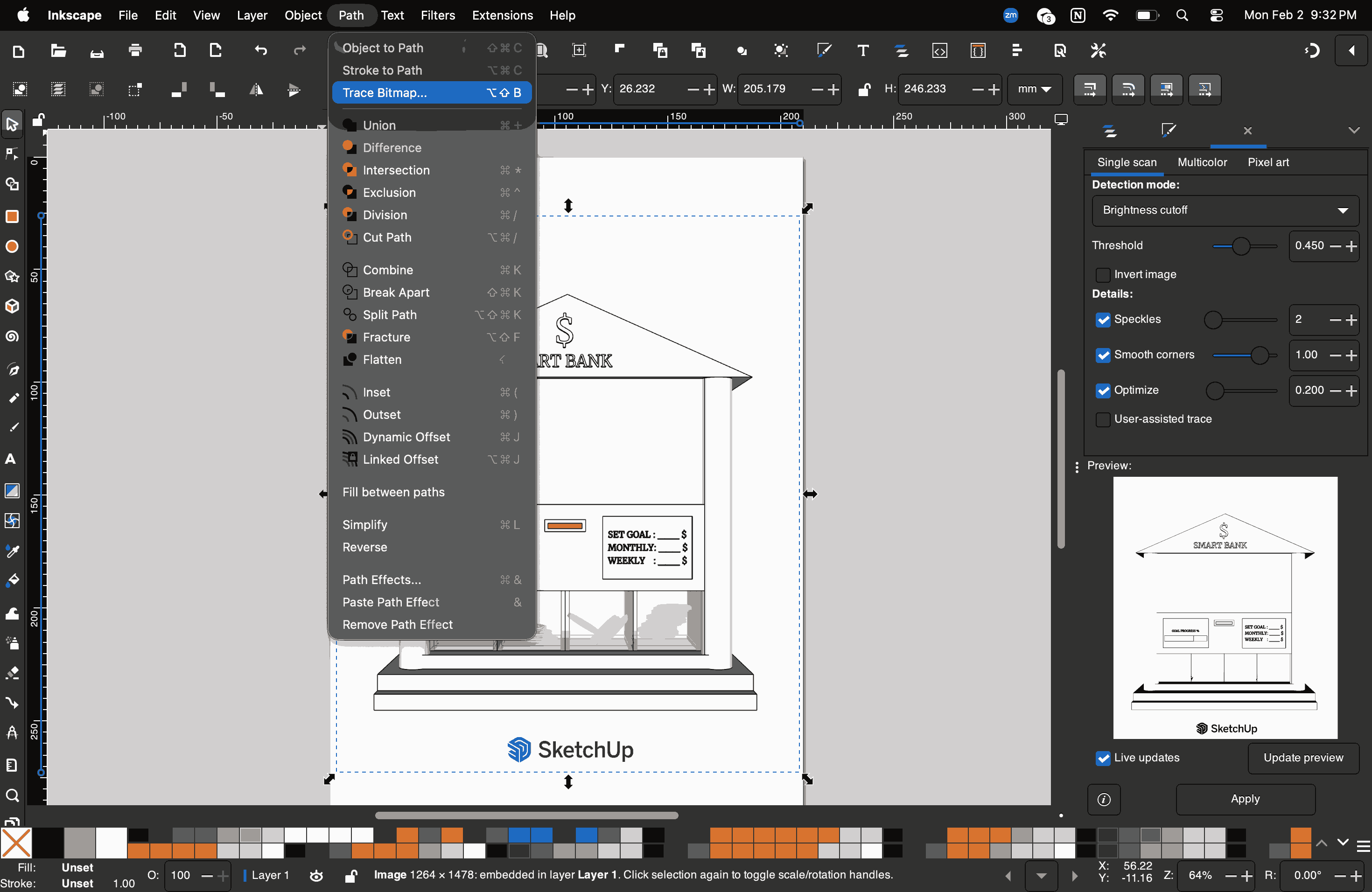
For this exploration, I downloaded a png image of Bubbles from The Powerpuff Girls from this website. I tried using the 'Trace Bitmap' option on Inkscape to convert Rastor images to Vector, a very simple way to explain this would be to say how you can turn your images to high quality line work without them getting pixelated while zooming in.
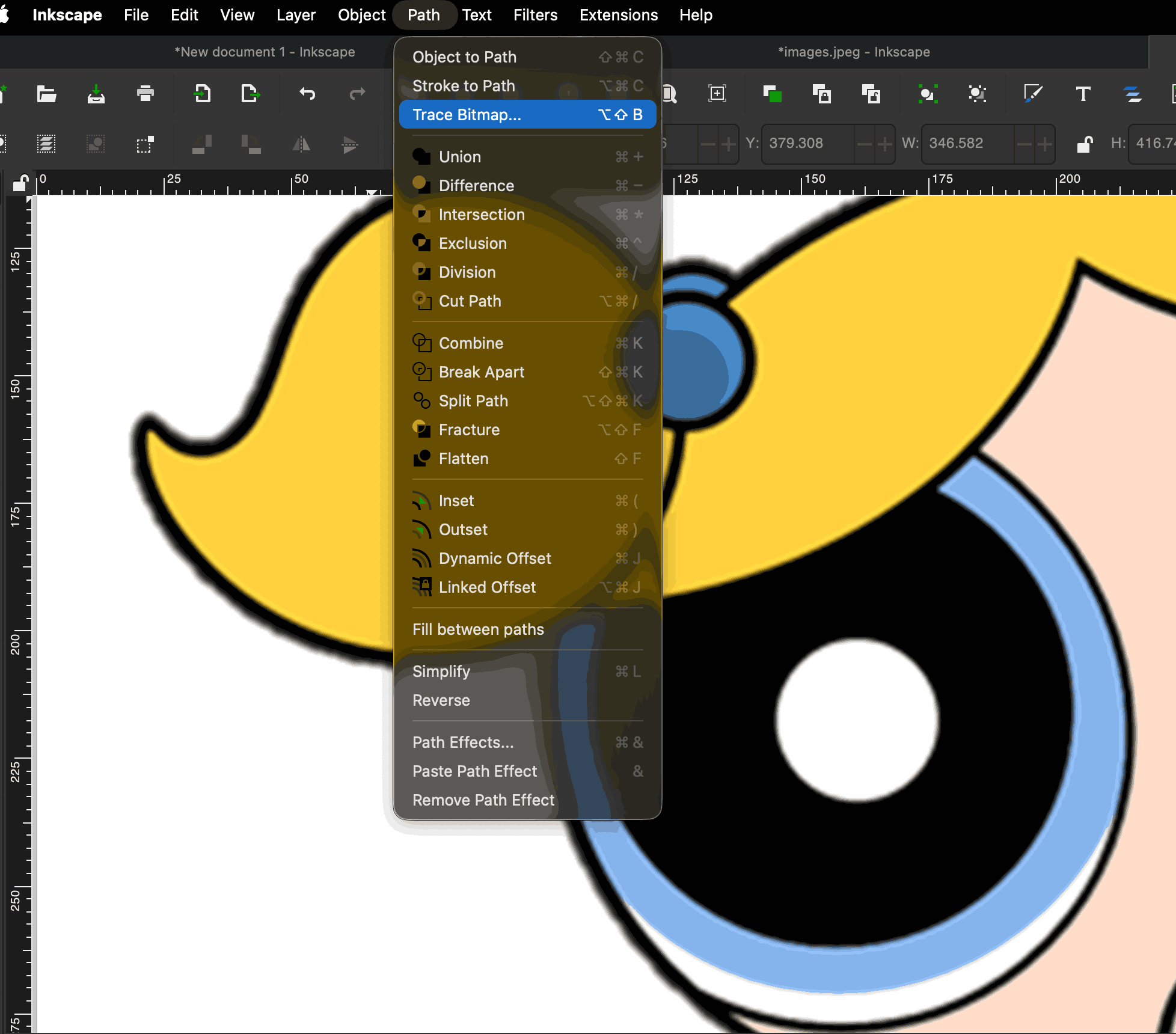
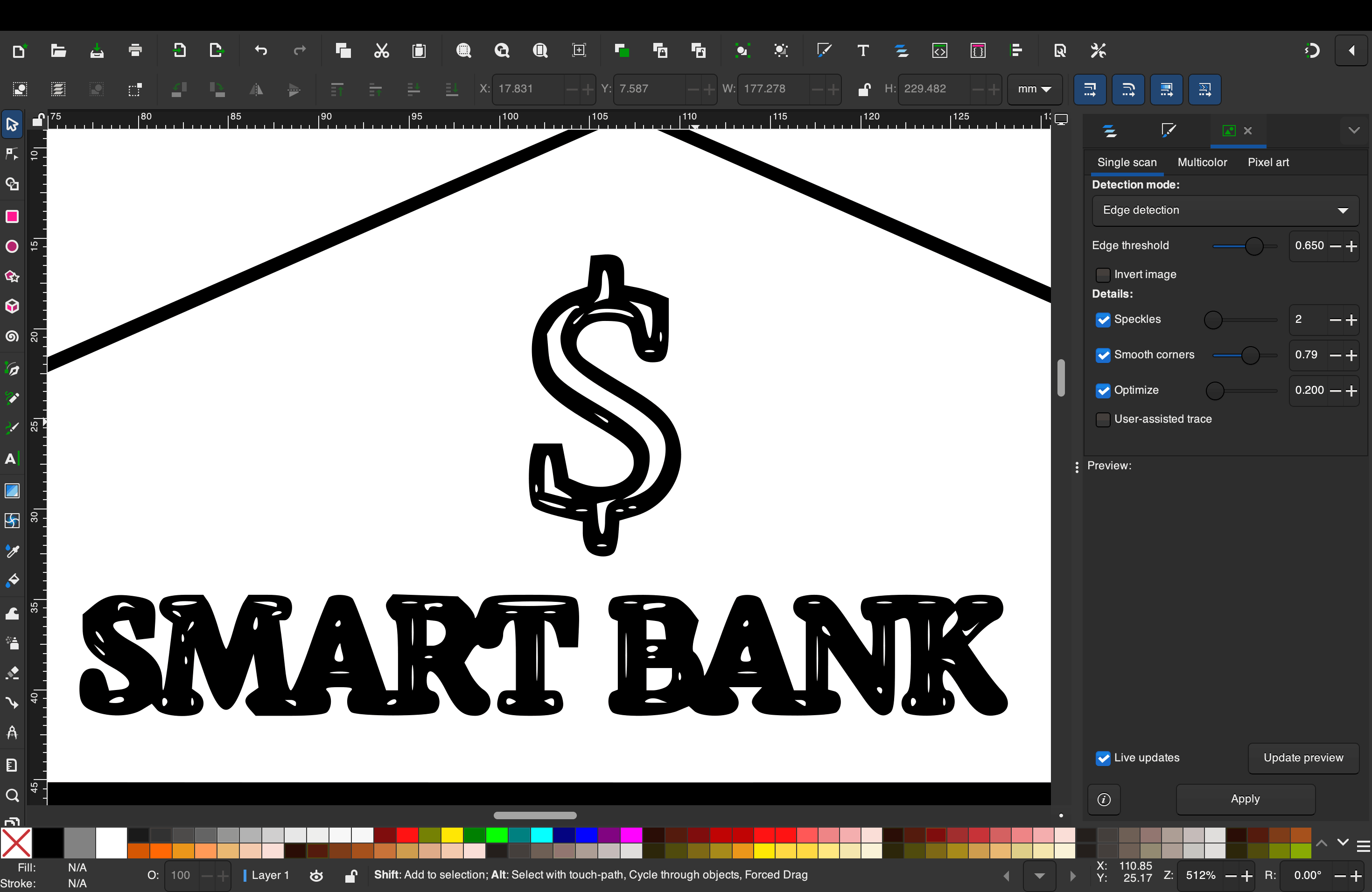
See how the quality is being compramised while zooming in, you can see the individual pixels if you zoom in further.
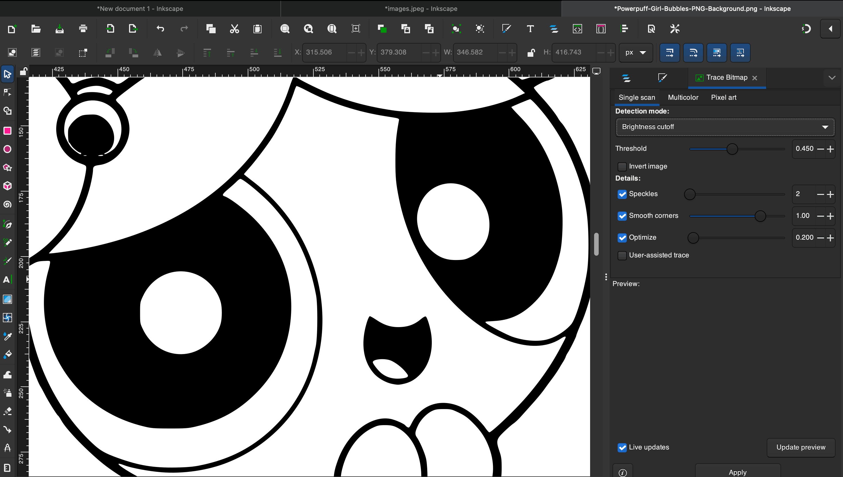
The above image shows the zoomed-in view of the image after tracing the bitmap; see how the line quality has become sharper. This little exercise explains the concept of Raster and Vector images. The main difference between raster and vector graphics lies in how they are constructed: raster images are made of a grid of tiny colored pixels, while vector graphics are built from mathematical paths (lines and curves).
I used Inkscape and experimented with bitmap tracing using one of the screenshots from the SketchUp model I made. The dollar sign I created earlier was now a PNG raster image, and I applied the bitmap tracing function to convert it into a vector. I then manipulated the vector further to better suit my needs.


Photopea
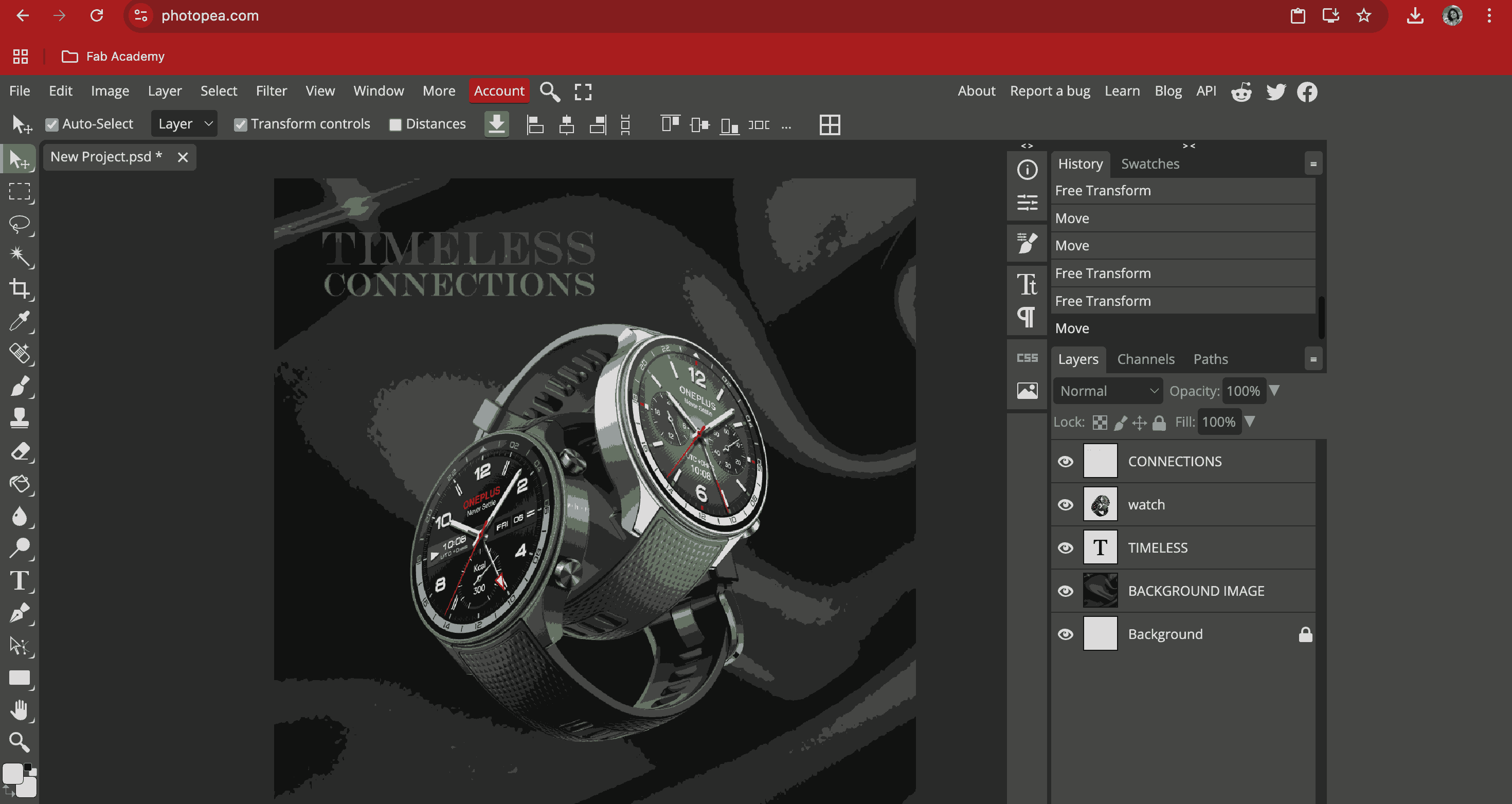
Photopea Online Photo Editor lets you edit photos, apply effects, filters, add text, crop or resize pictures. It is a free, web-based graphics editor that functions as a powerful alternative to Adobe Photoshop. Since I have worked in Photoshop previously, the workspace and commands were all very easy to adapt. We did the following exercise to get to know the software. This one works in both Rastor and Vector.
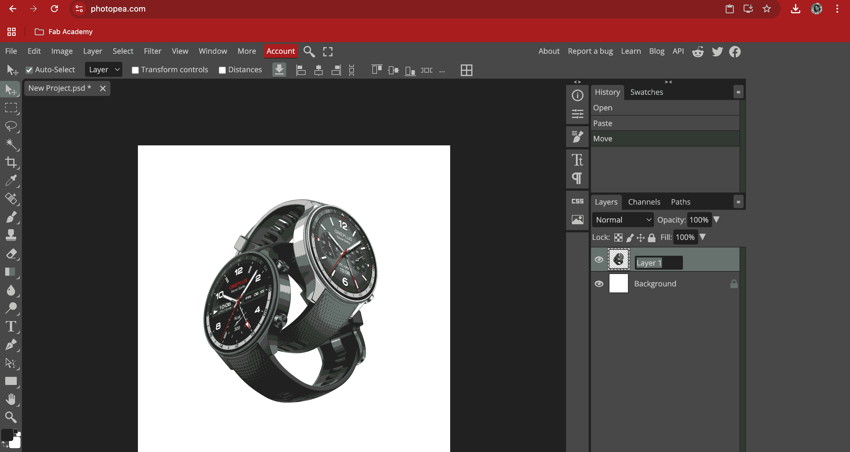
I downloaded a sample product image of a watch from this Website. Opened a new document as social media file size (instagram post). Opened the watch image and renamed the layer to WATCH. Tried adding text, the text tool automatically opens as a new layer:
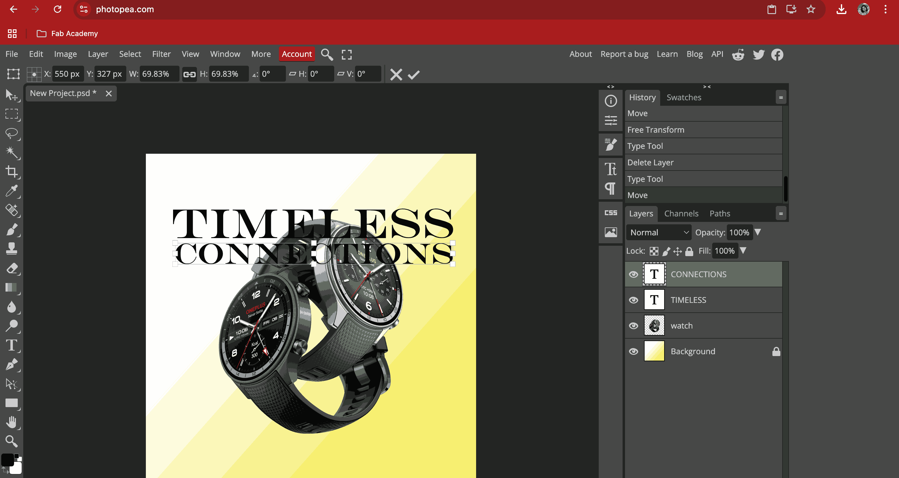
Tried rasterizing one of the text layers “Connections” to experiment blending options. Since the watches looked intertwined and connected, I choose to write ‘Timeless Connections’. Adjusted the text size and placement. Saved the file in psd format.
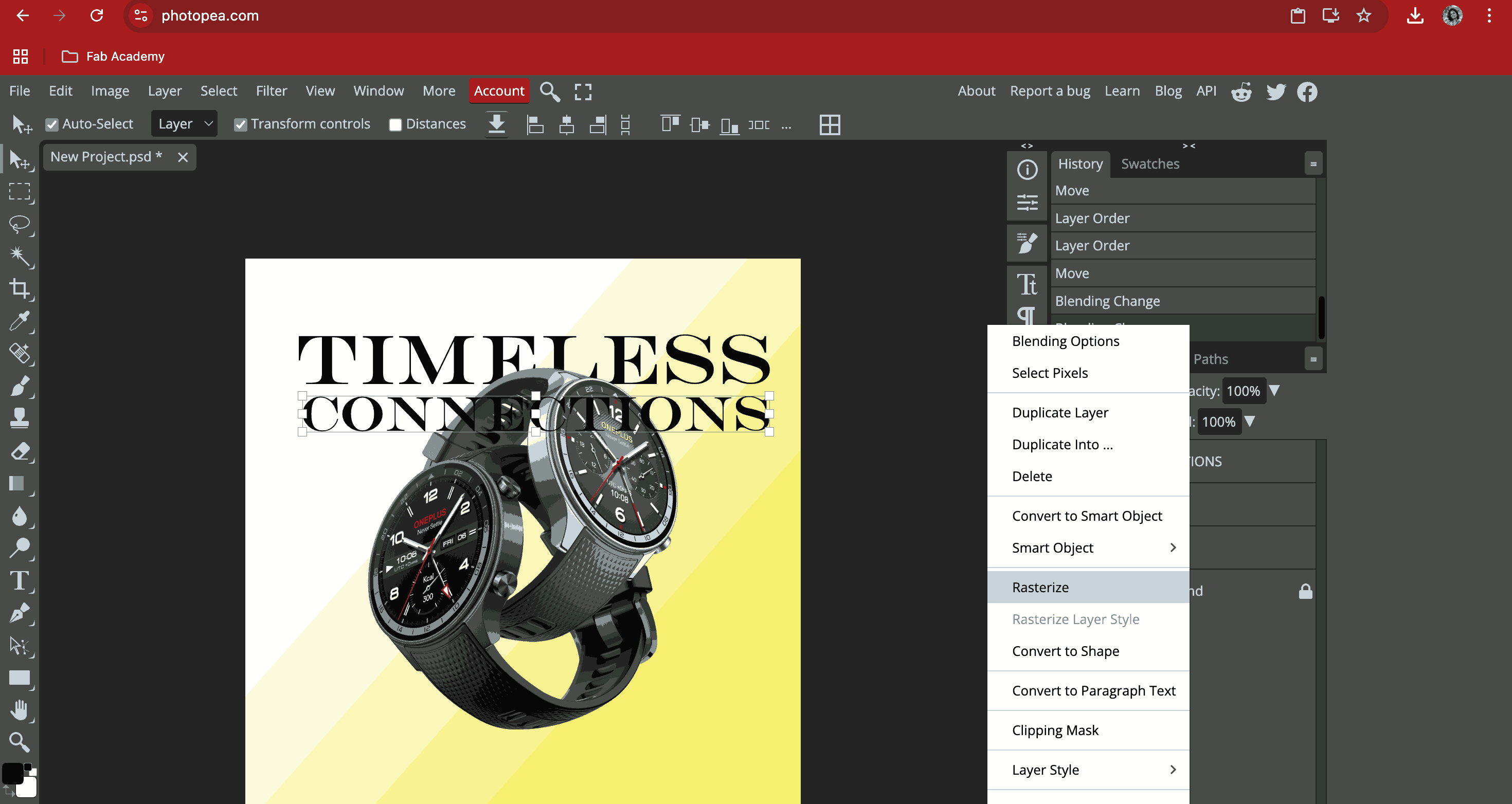
Searched for a suitable background for the ad i was trying to create.
SketchUp
Since I have previously worked on SketchUp, I tried sculpting a bottle with an open cap, tried assigning material and made a scene animation video.
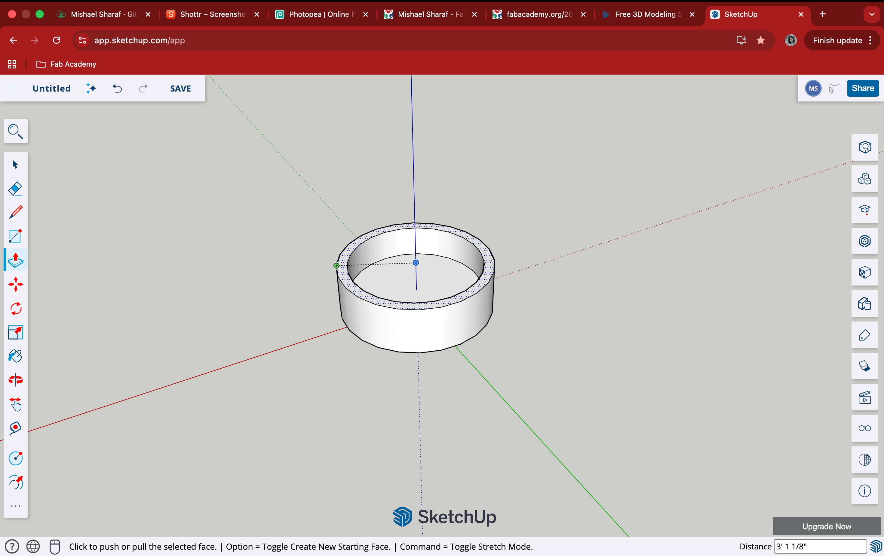
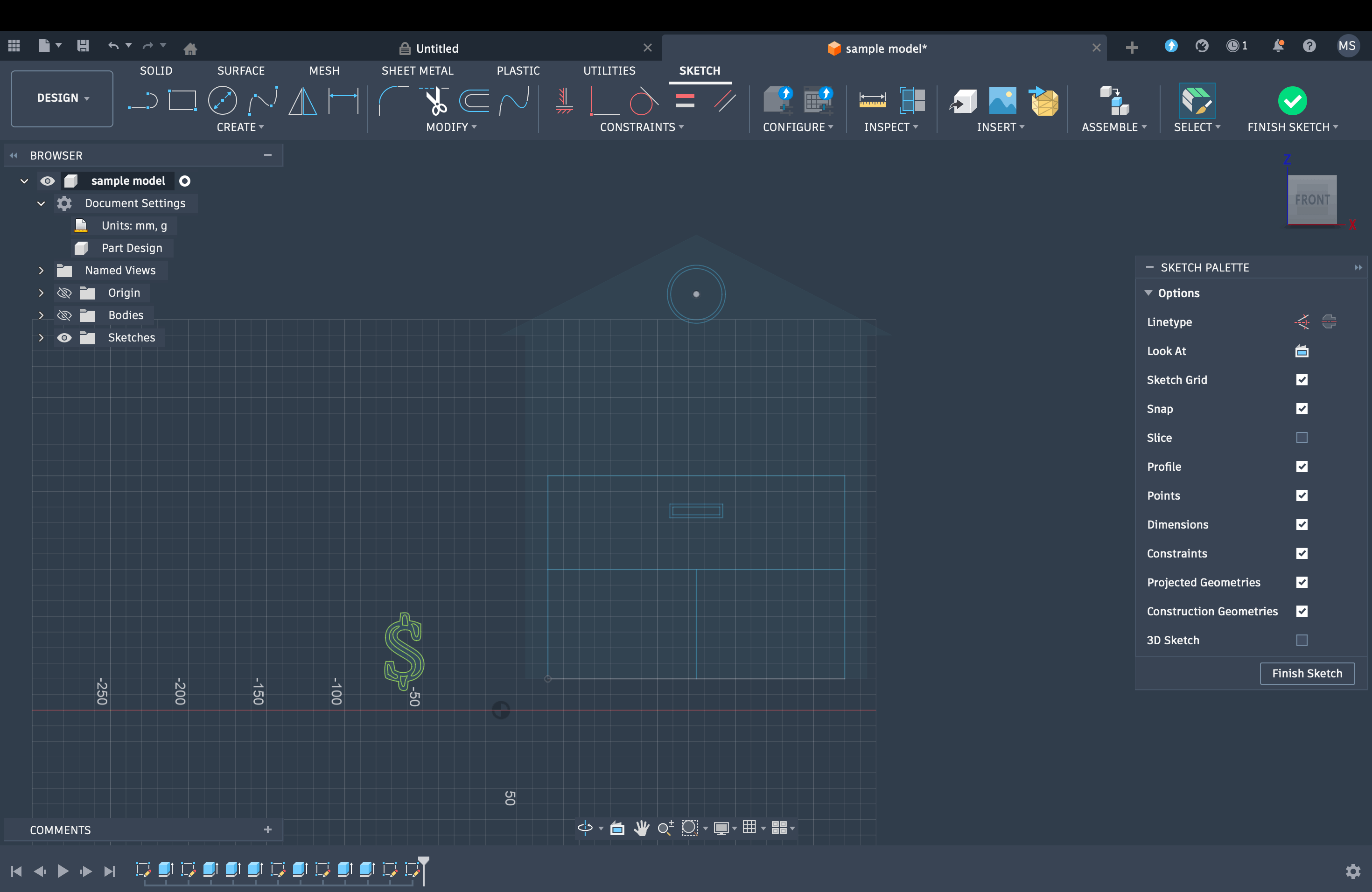
SketchUp is usually very easy to use because of the extremely simple interface it has. Everything works pretty straight; for example, if you need to sculpt a cube, draw a square either using a line or use the polygon tool. All closed planes can be extruded. There are views available such as TOP, FRONT, LEFT, & RIGHT. For the bottle, I started with a simple circle and then extruded it, followed by creating an offset before extruding further to create the hollow bottle container.
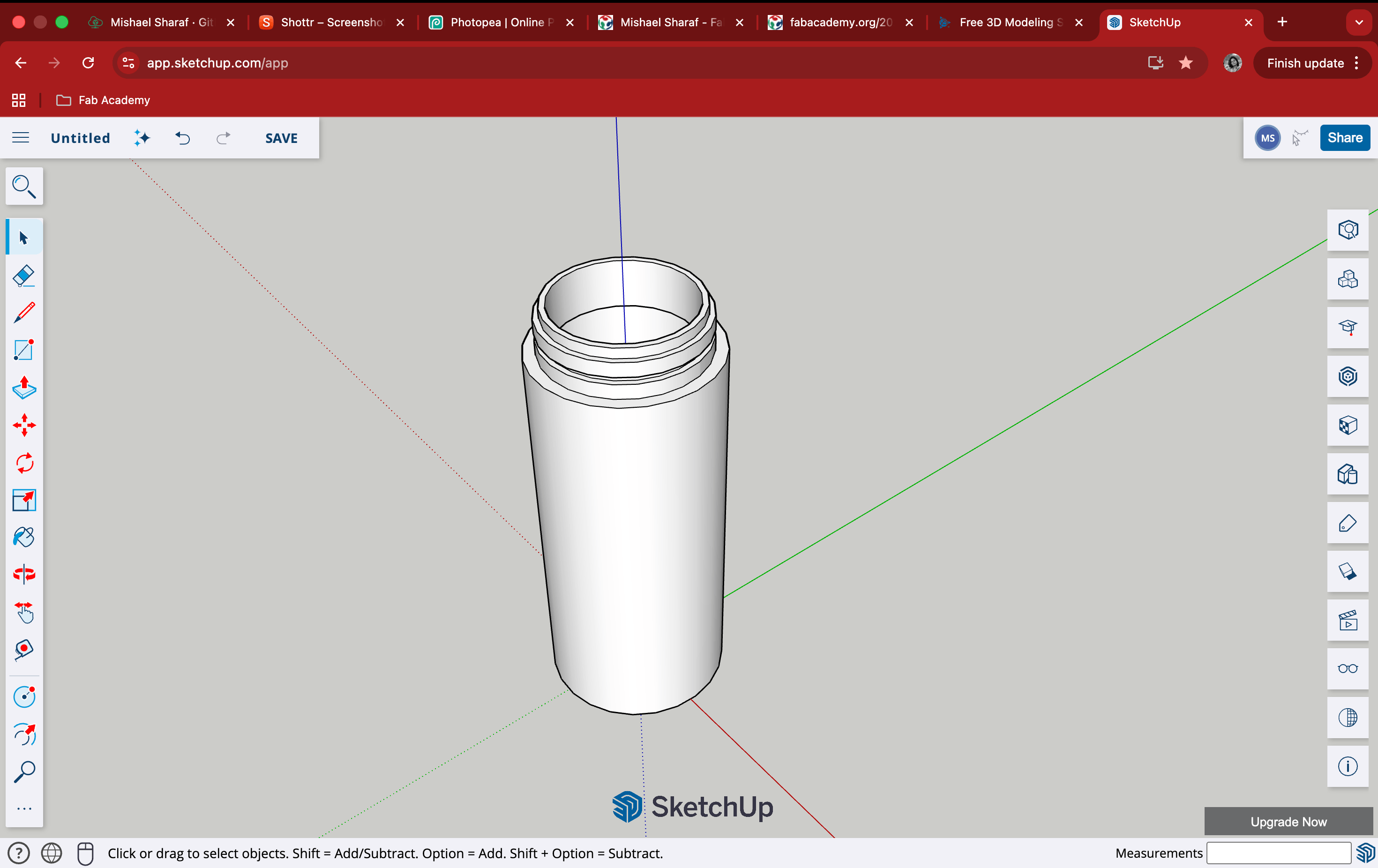
Repeated the steps using the offset and extrude tool to create the bottle neck I wanted. To show water inside the bottle, I made a copy of the circle at the bottom of the cylinder and placed it inside the bottle till where I wanted the water level to be. Then, while assigning material to the object, I tried glass, metal, and water.
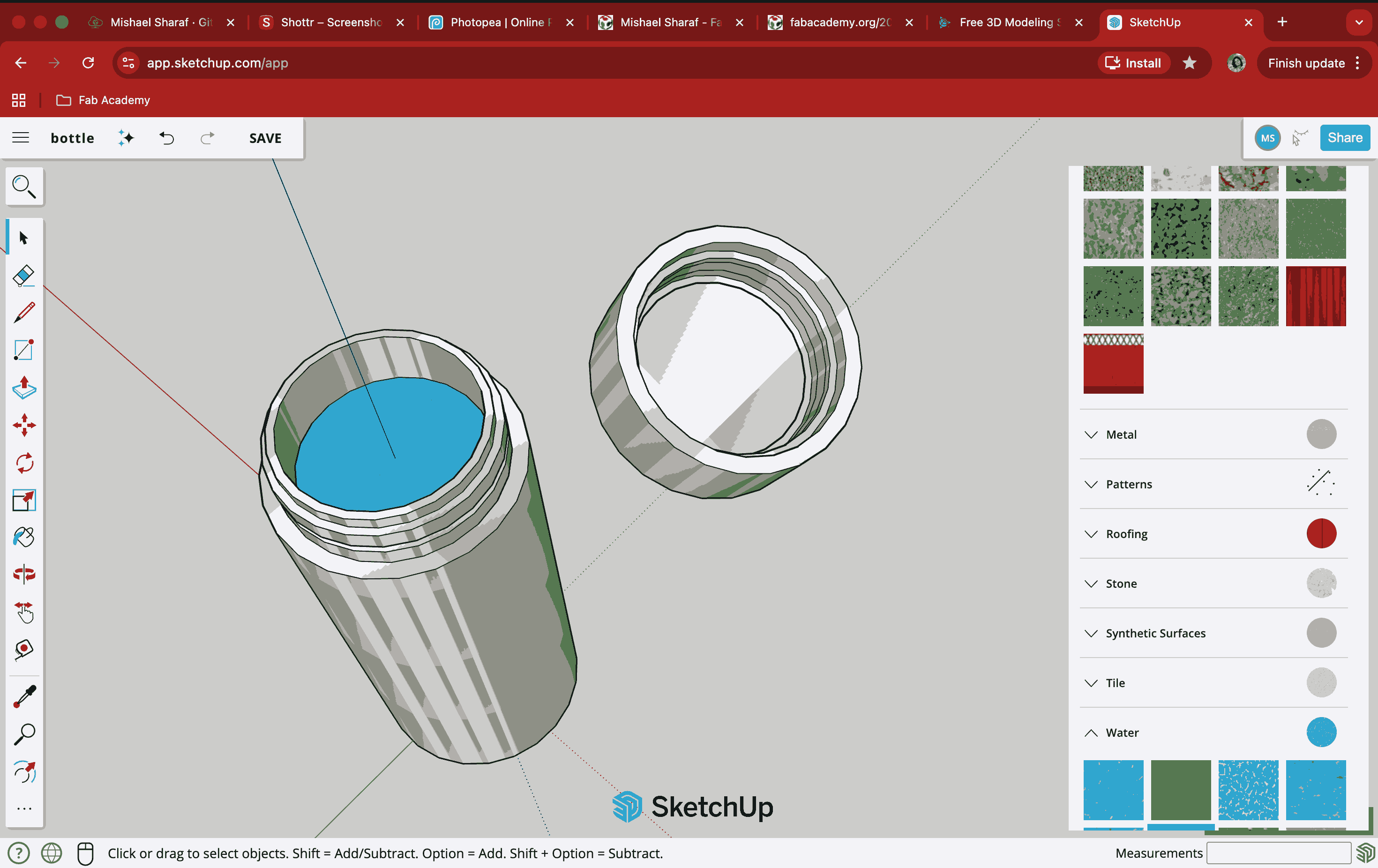
It was at this point that it occurred to me that, since this version is free, it did not have many of the original commands, such as Boolean options. For achieving the same grooves on the cap, I then created a copy of the bottle neck and built it outwards to make a cap.
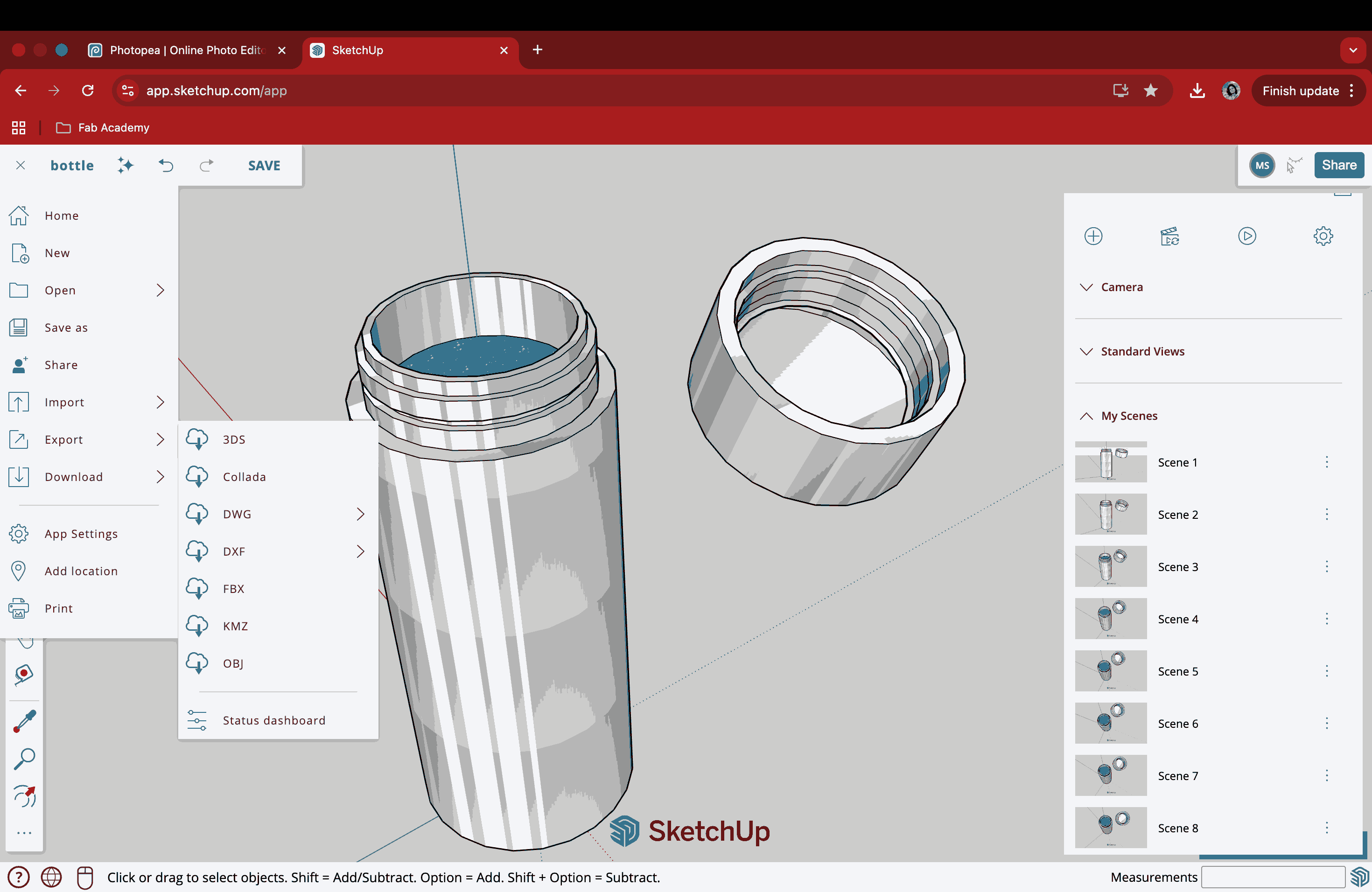
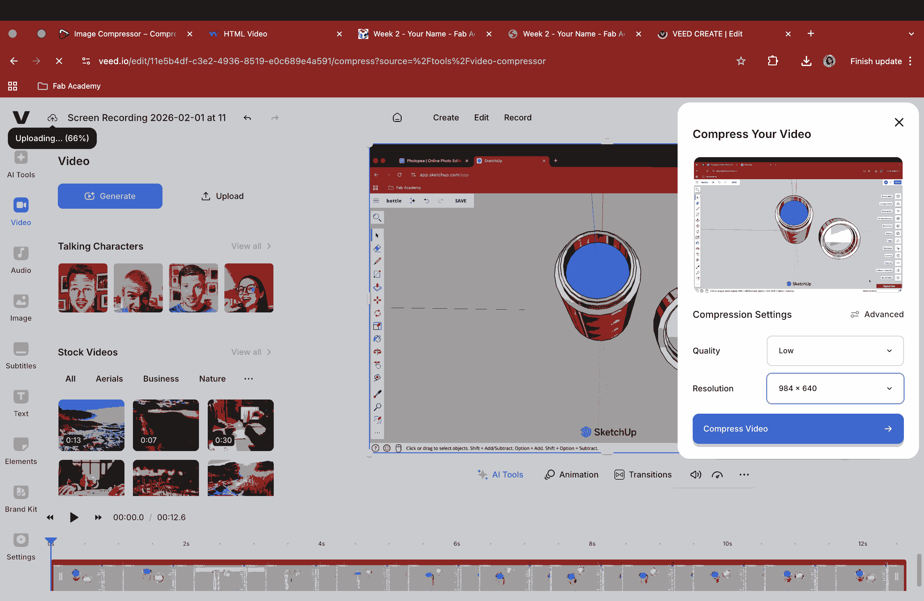
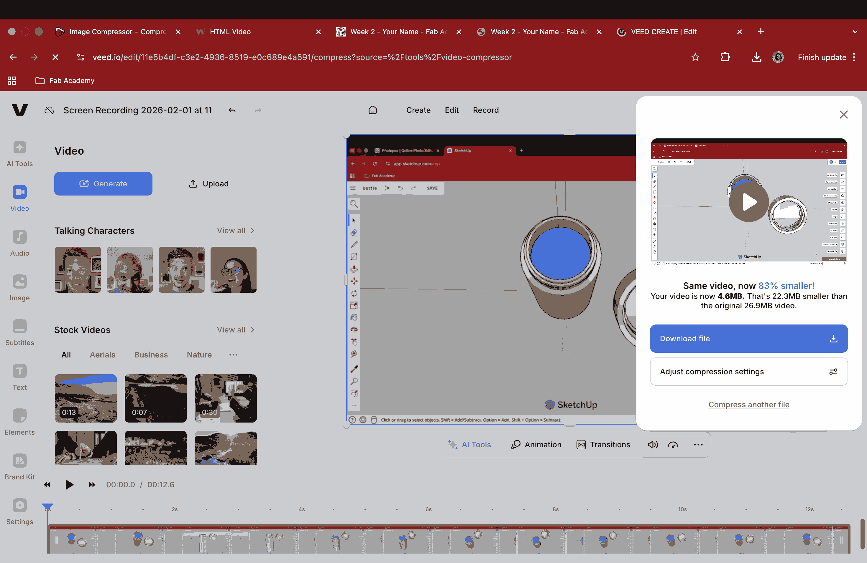
Then, I created scenes for a better view of the model from various angles. Now, since this is a free version, the video file could not be downloaded. Hence, I did a screen recording and then compressed the video for later use.
Scene Animation on SketchUp
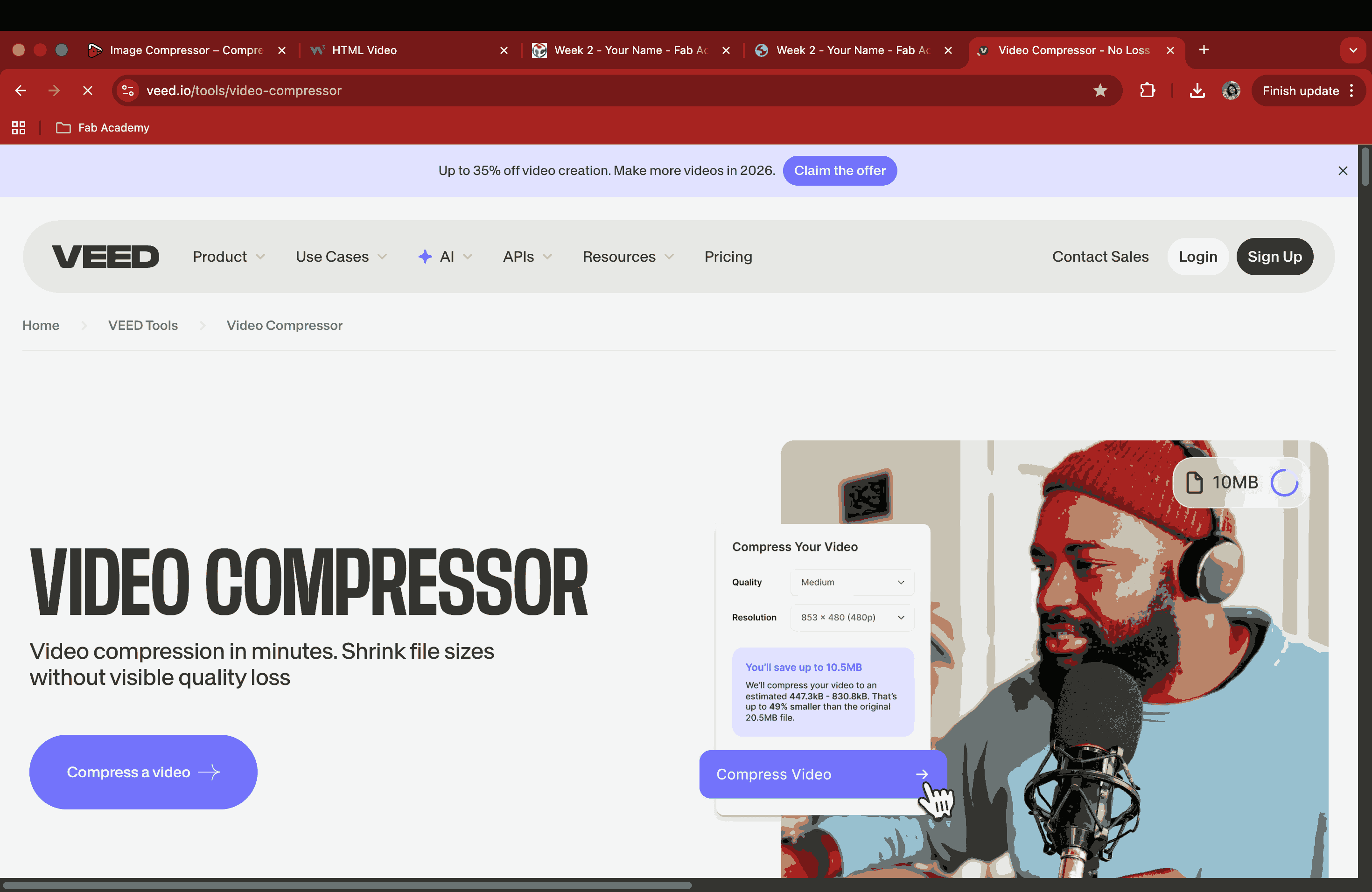
A video compressor called VEED was used to reduce the video size from 44 MB to 1.3 MB.
2D and 3D Modeling of a Potential Final Project
Since it was my first time using Fusion 360, I couldn’t figure out the basic functions or keep up with the pace of working within a day, which eventually became frustrating. Afterward, I decided to model my previous sketch using the free web version of SketchUp. For the time being, this is where I’m able to work faster, but in the coming weeks, I plan to try my hand at Fusion again for better results.
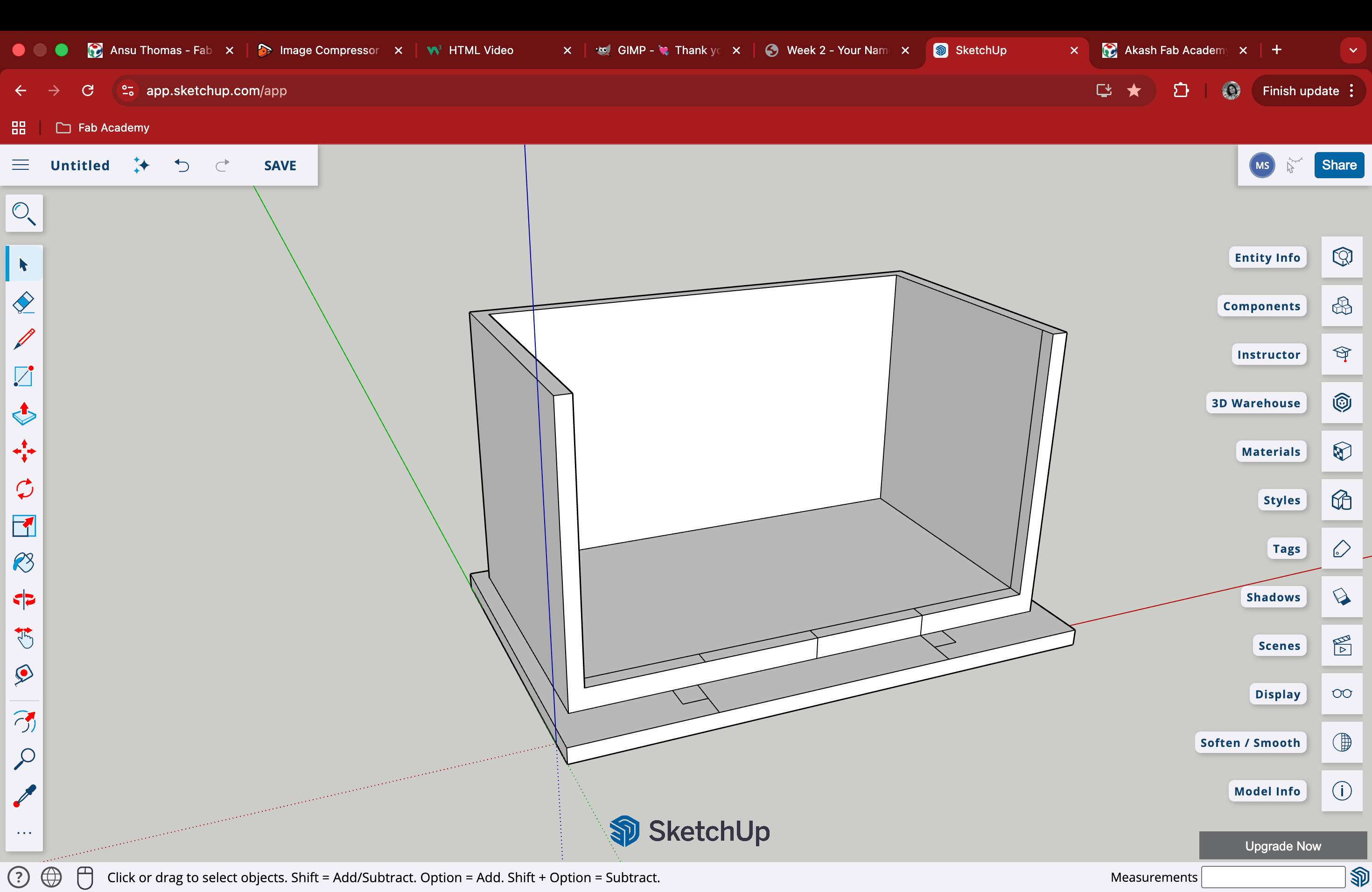
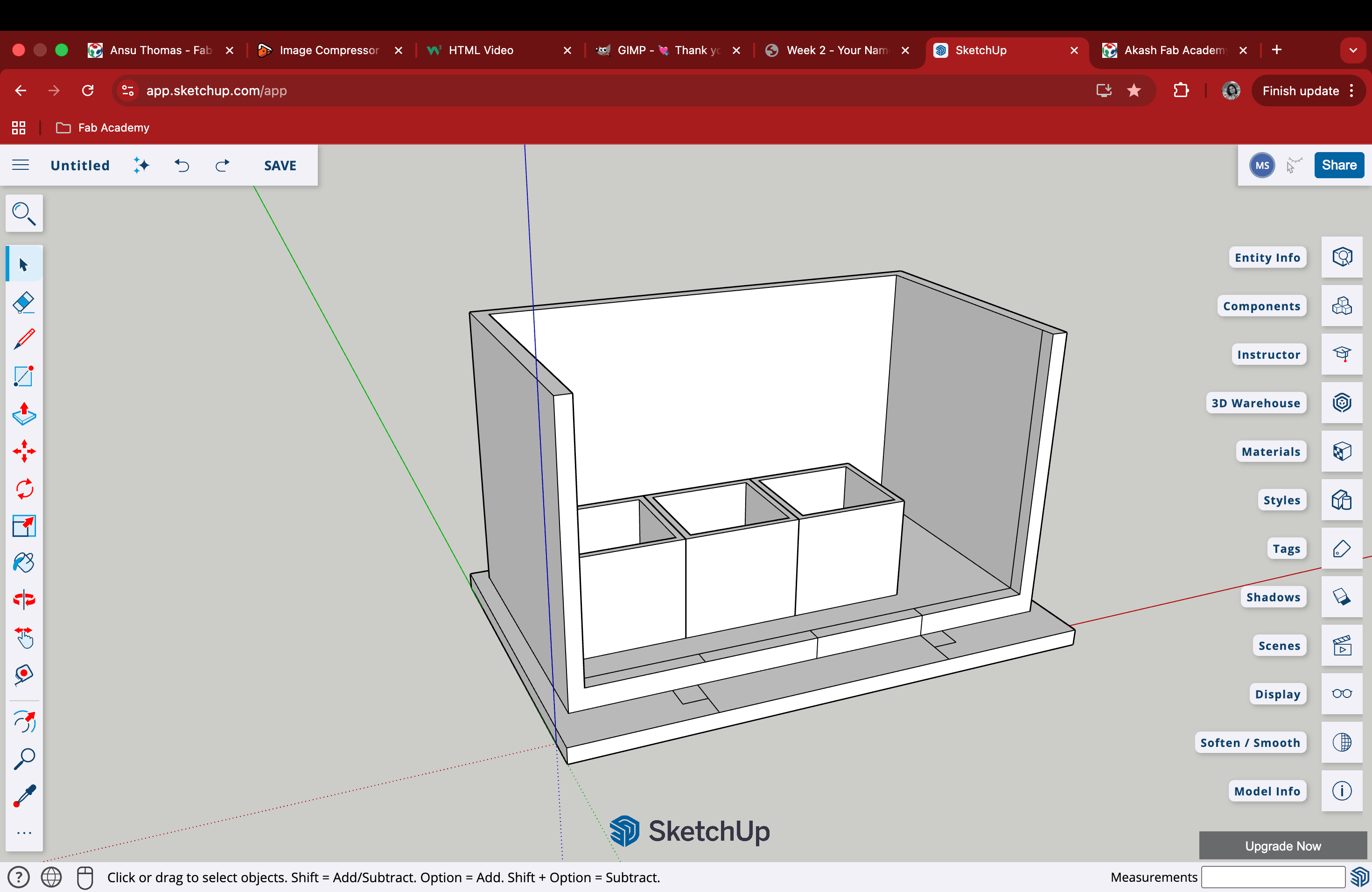
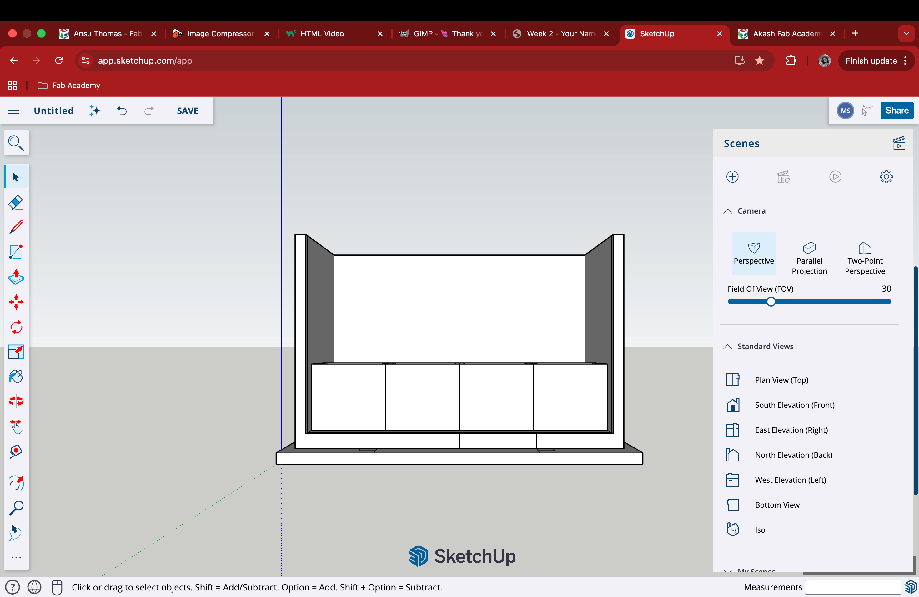
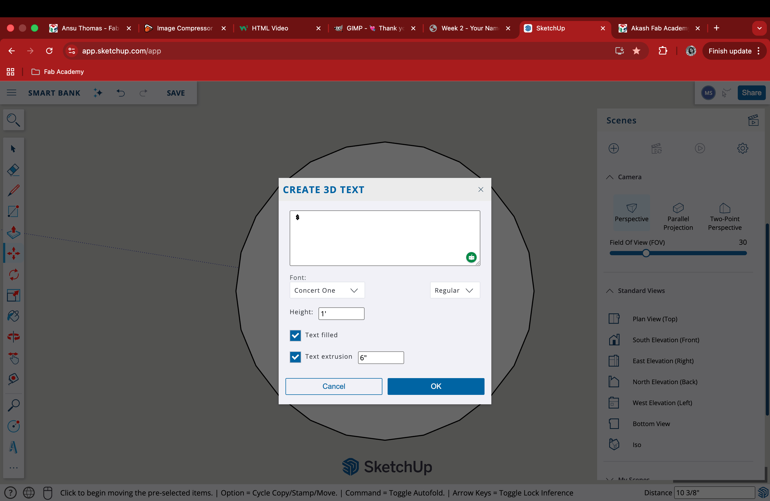
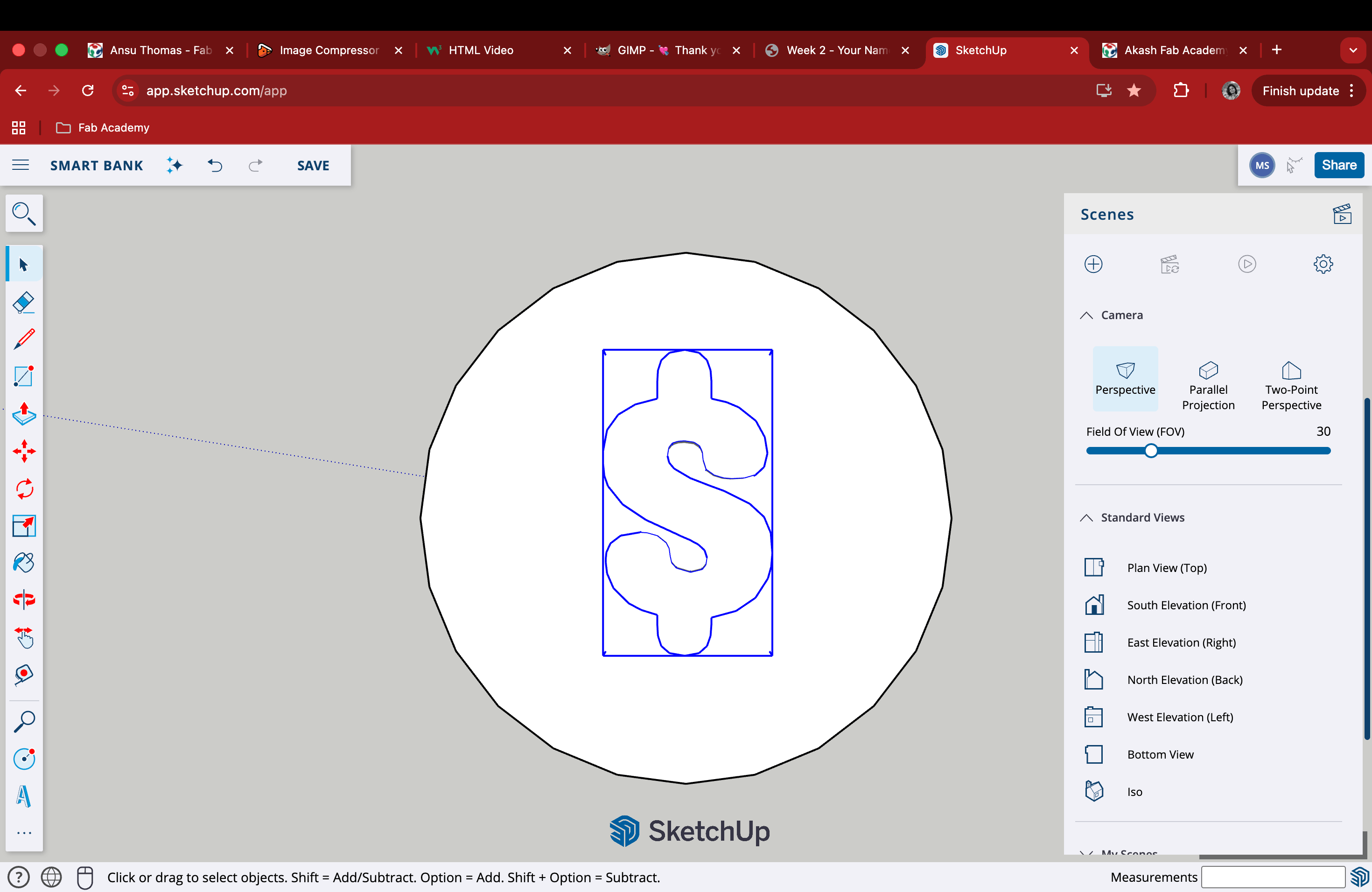
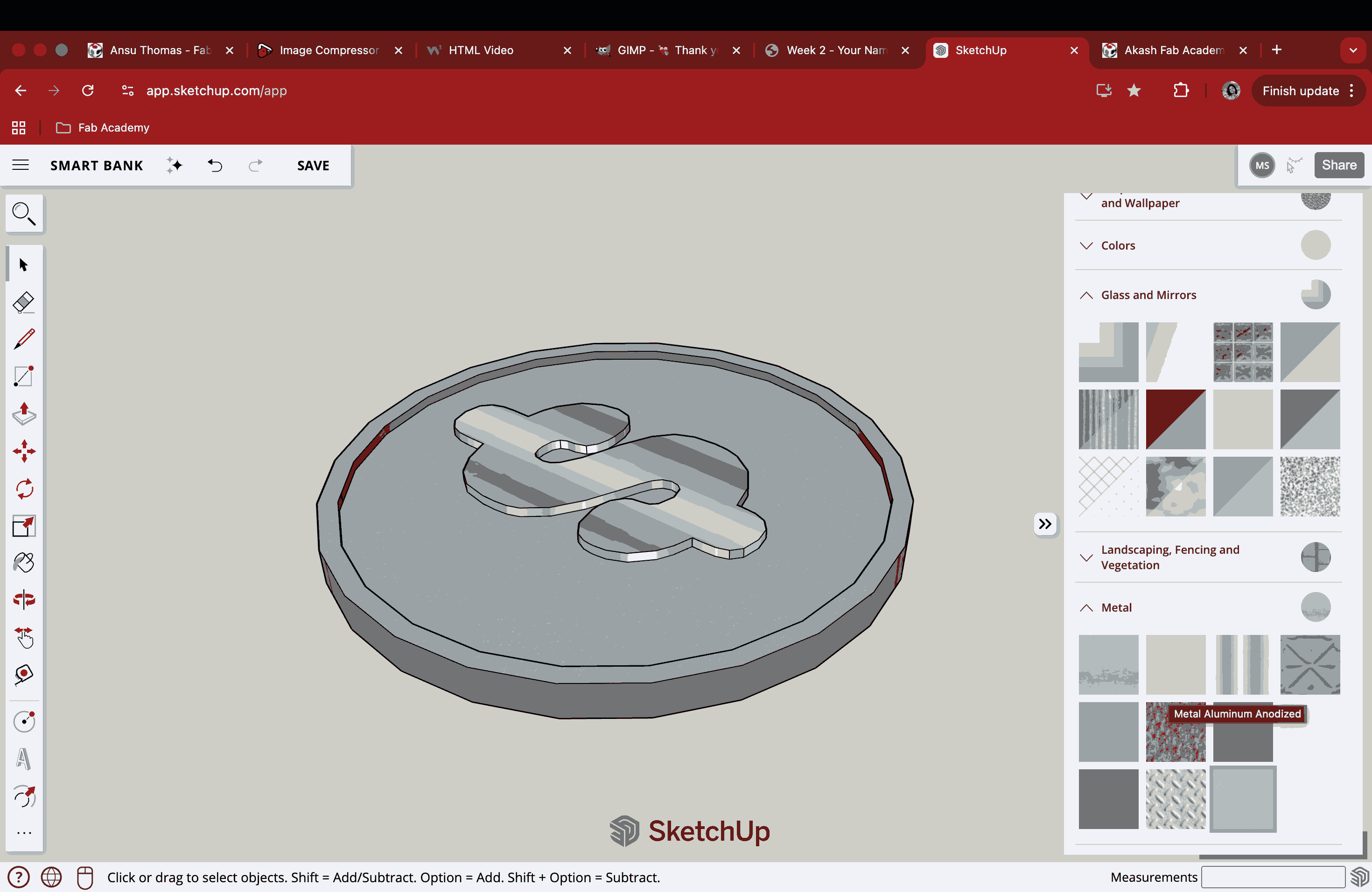
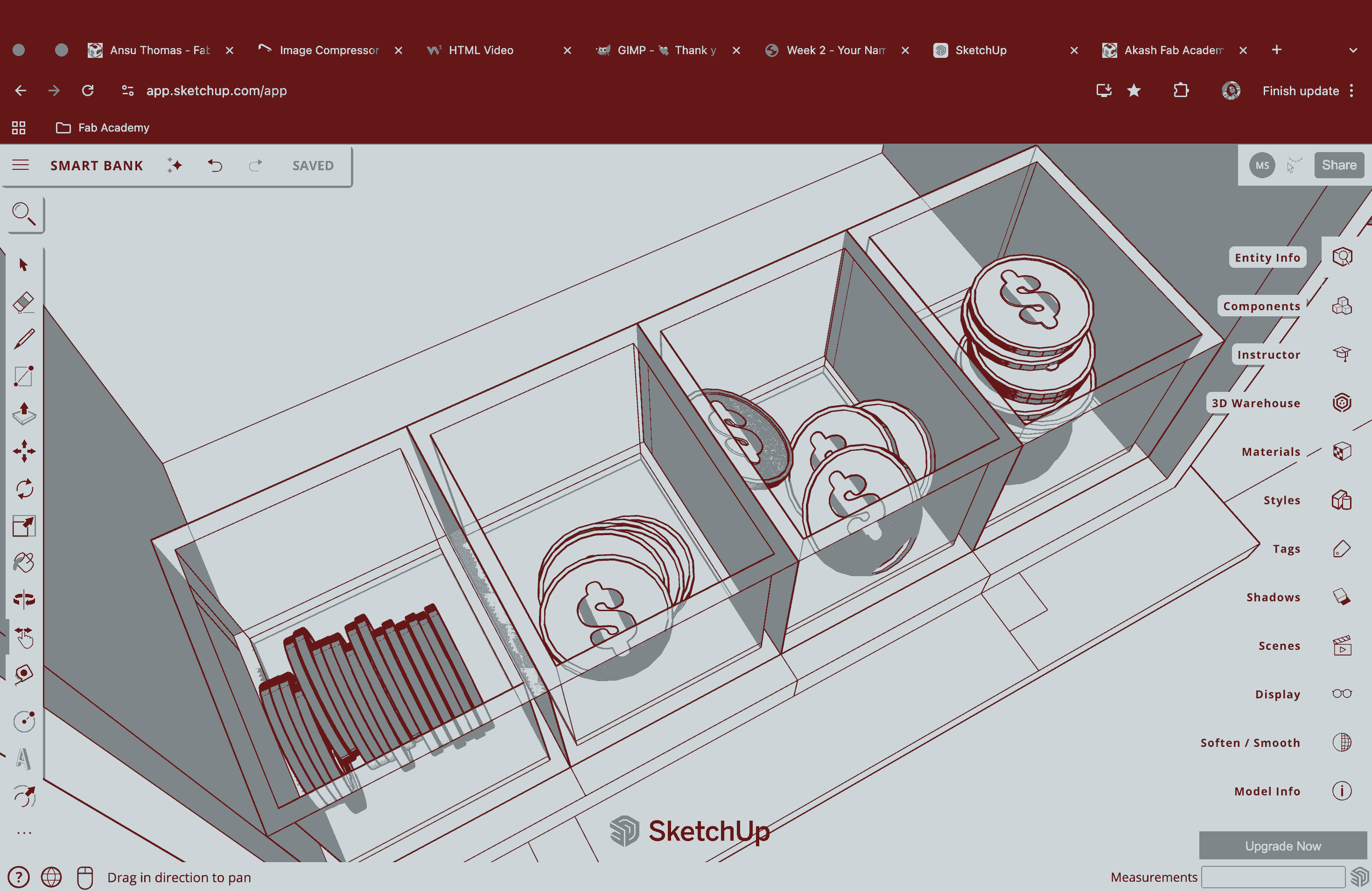
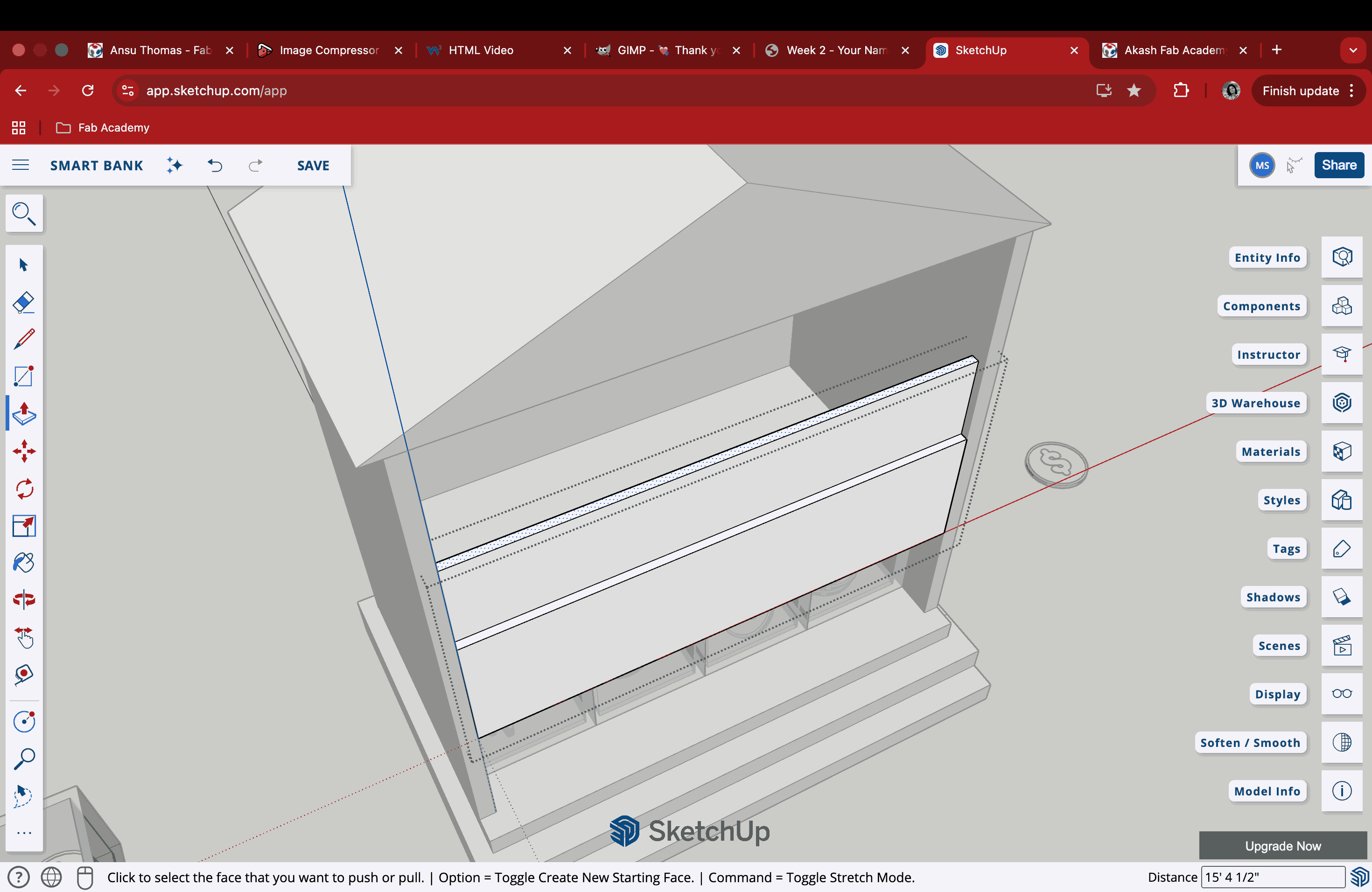
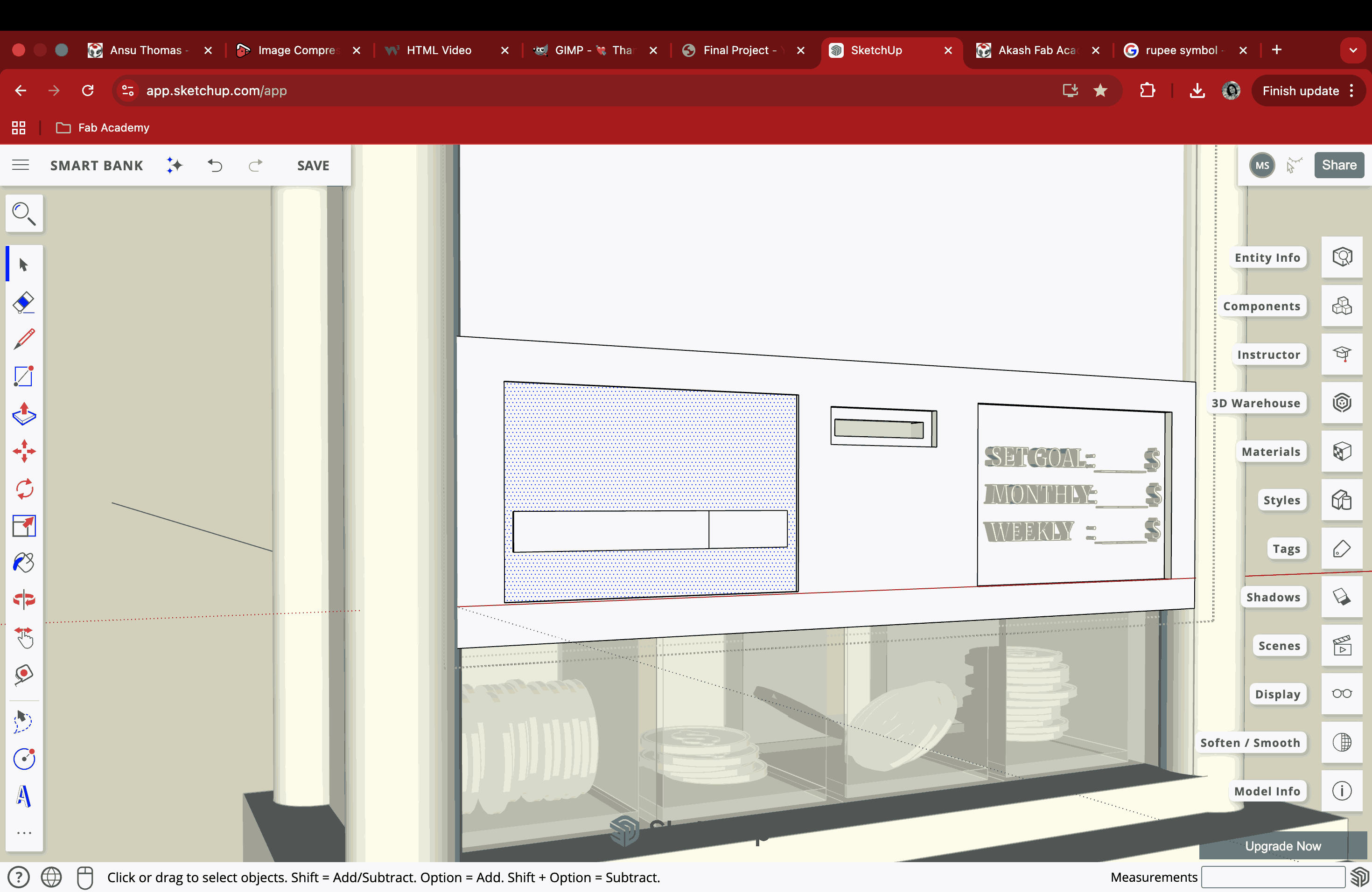
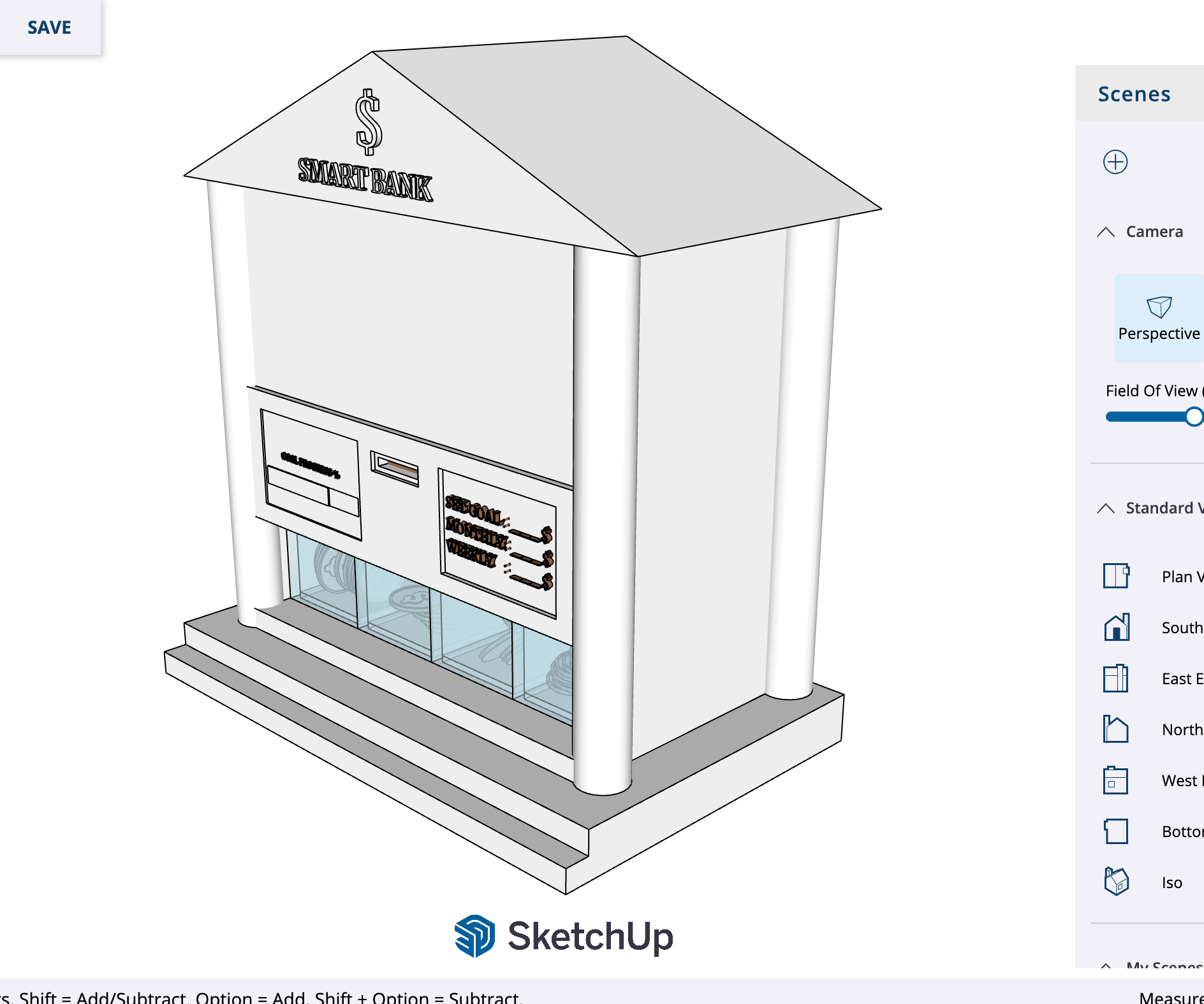
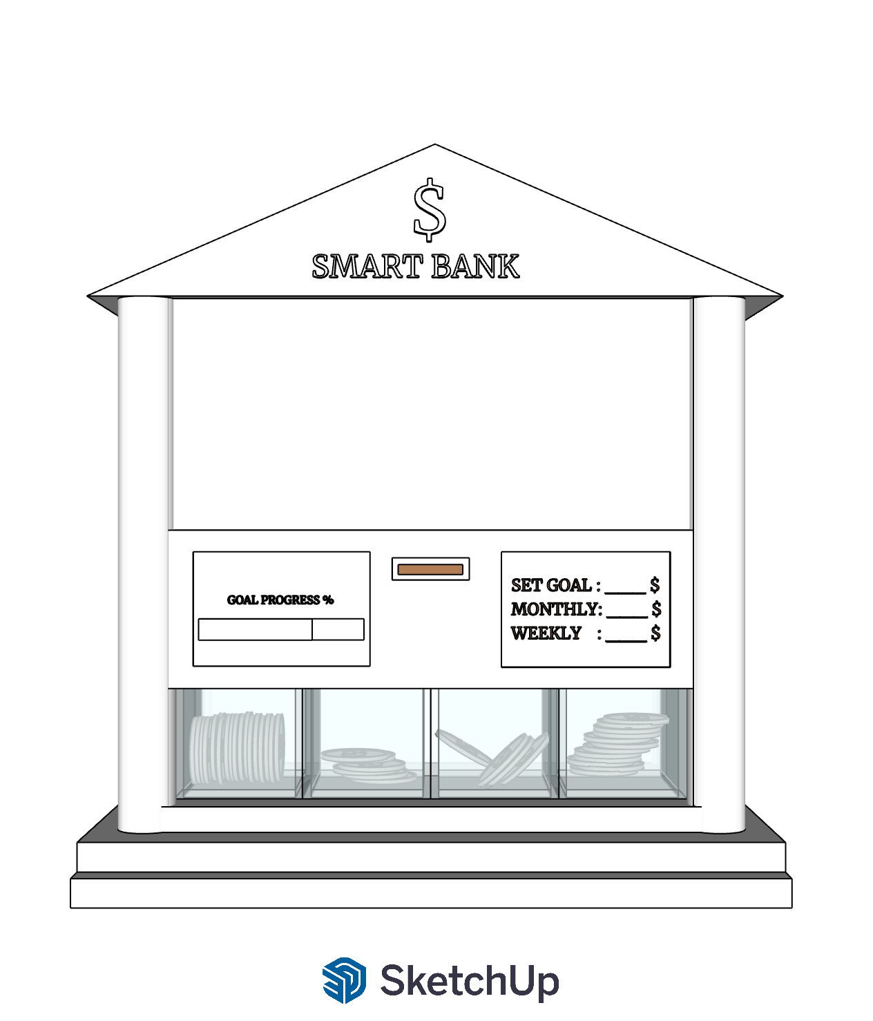
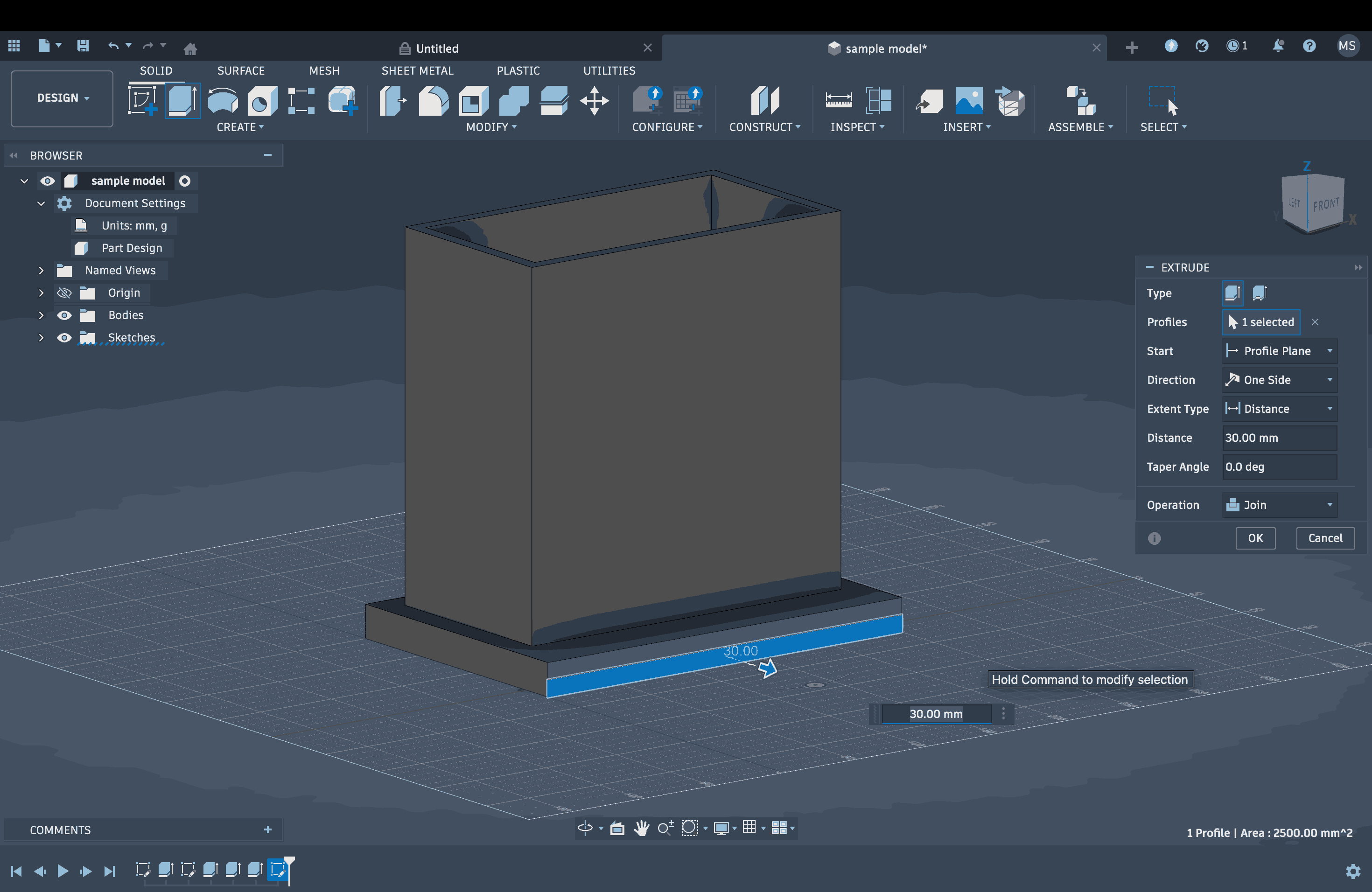
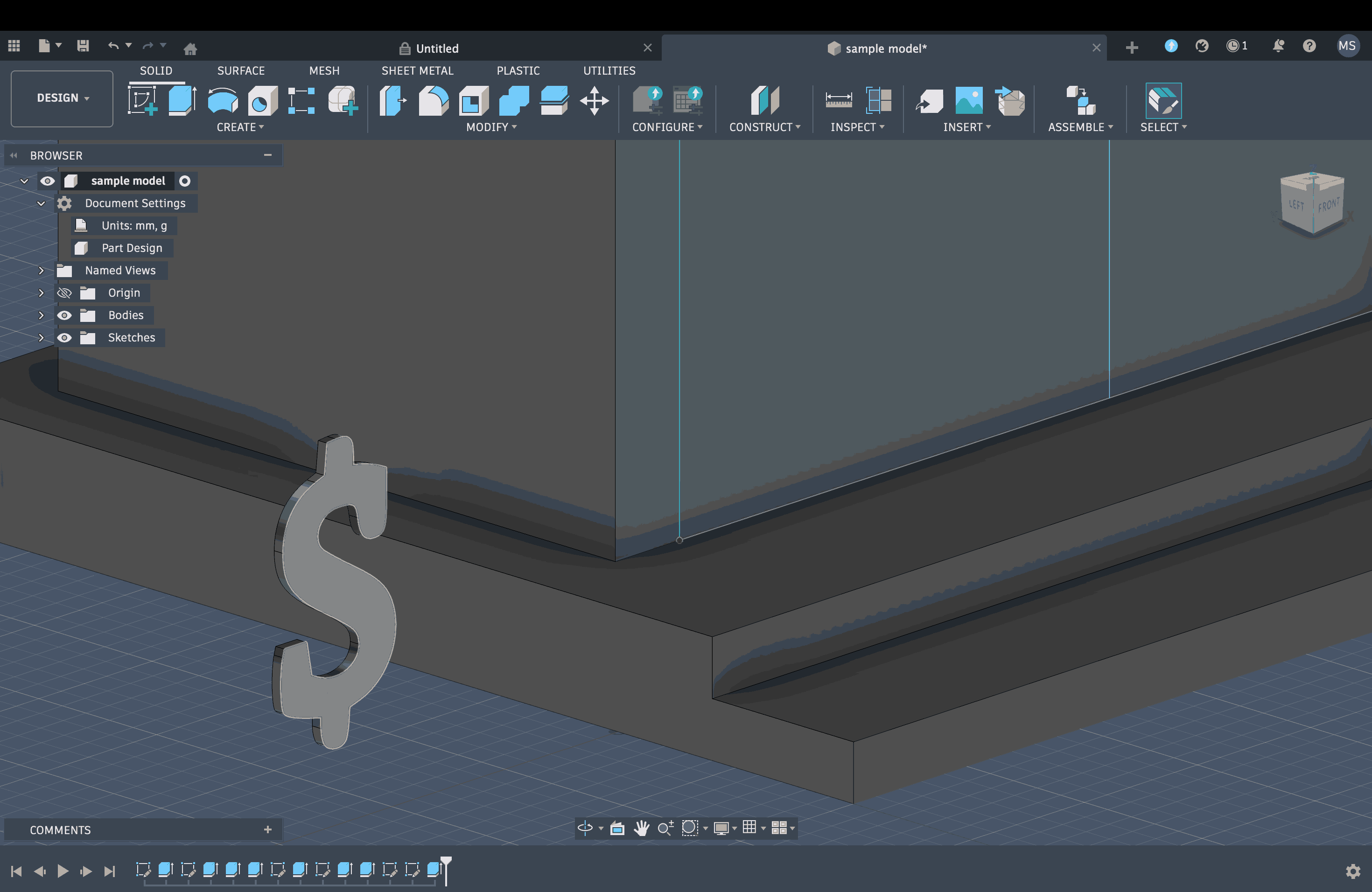
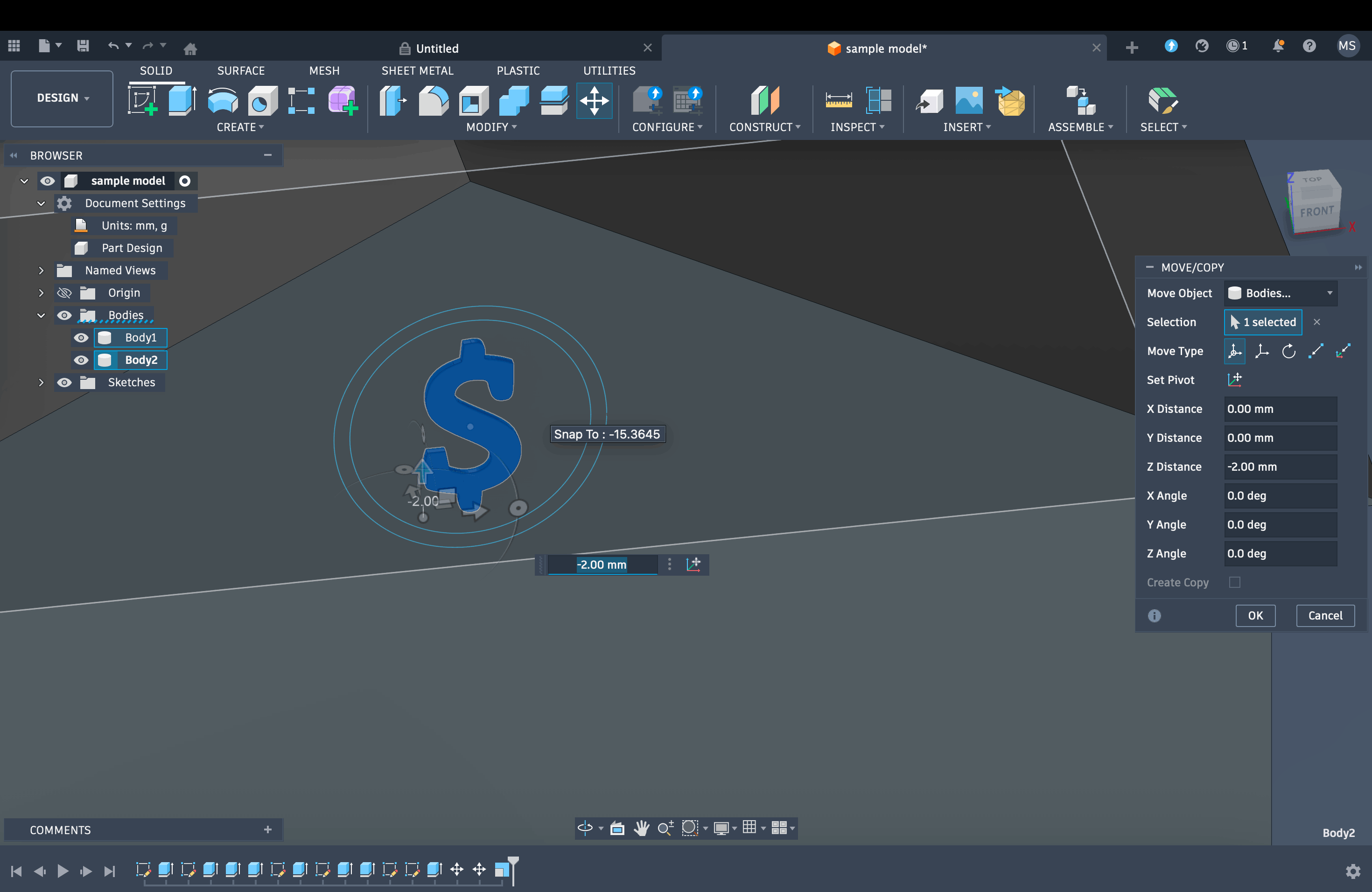
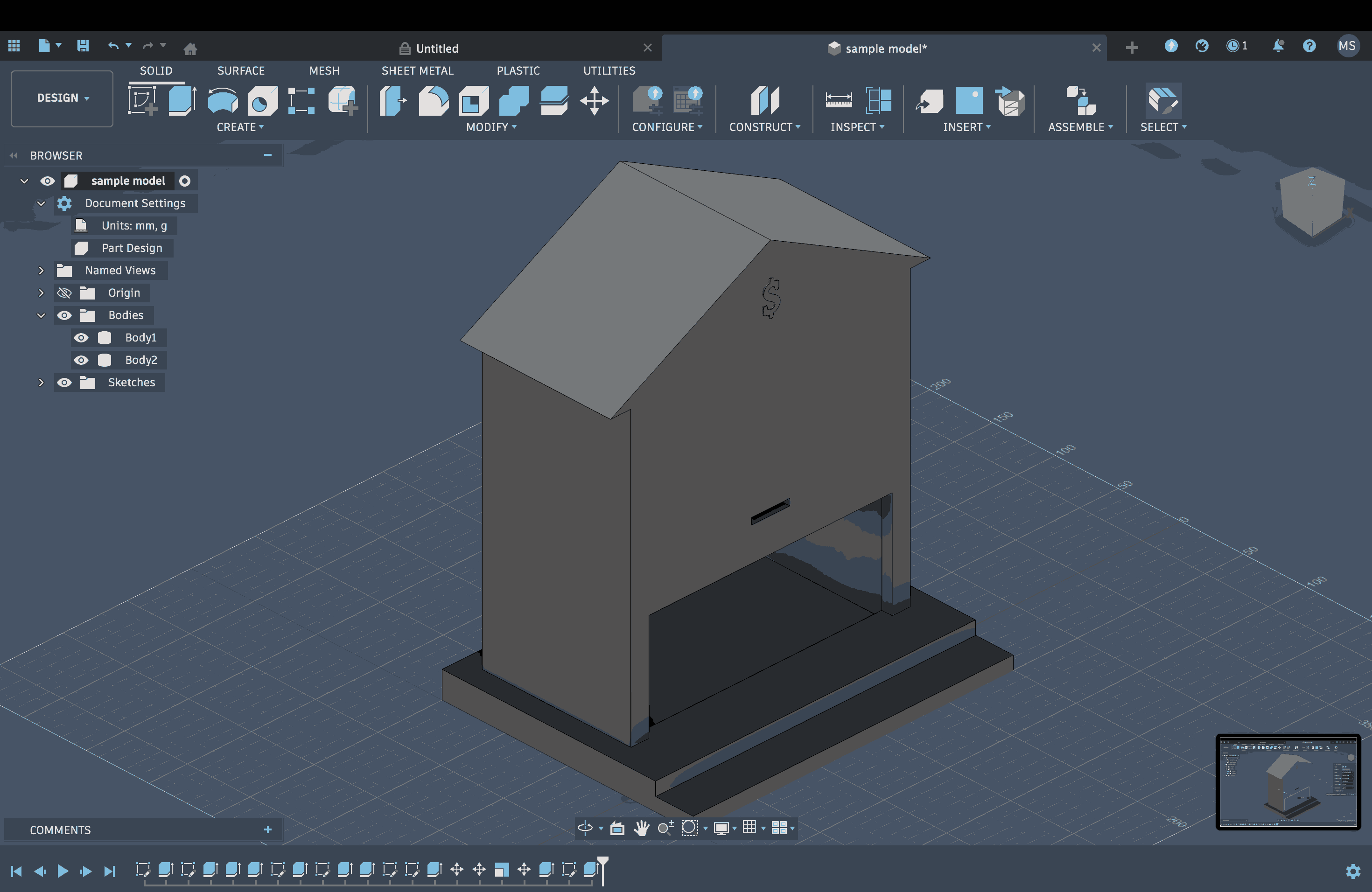
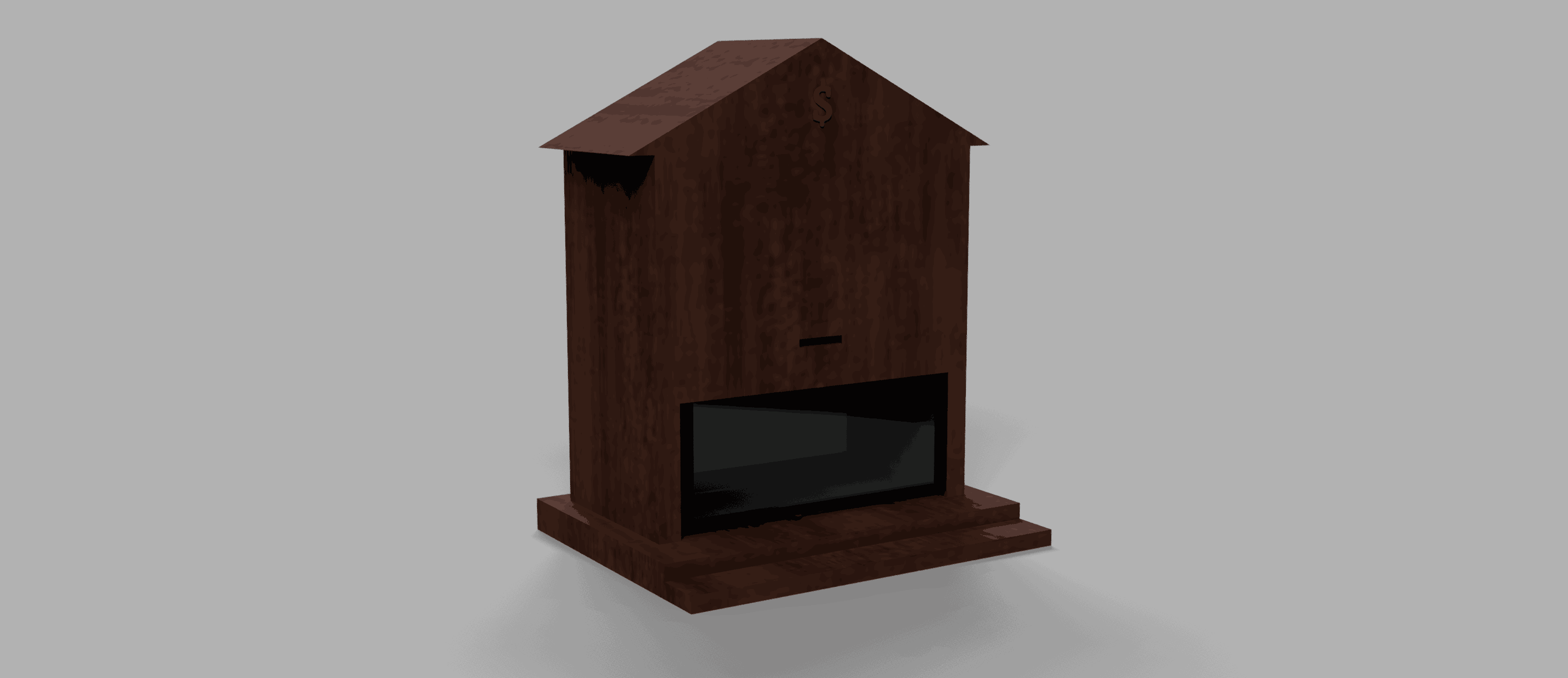
From the initial sketches I made, I had a rough idea of what the model should eventually look like. I started with a basic rectangle in SketchUp and extruded it to create a plinth, then used an offset to define the walls. I later extruded the walls on three sides, excluding the front. I made small containers to hold coins, which I created by extruding a circle. On top of the coins, I used the 3D Text Maker tool to add a dollar sign. I extruded the outer border of the circle with a slight offset to give it a more coin-like feel. Afterward, I made several copies of the same coin, adjusted their orientation using the Rotate tool, and stacked them in different ways in each container to show randomness.
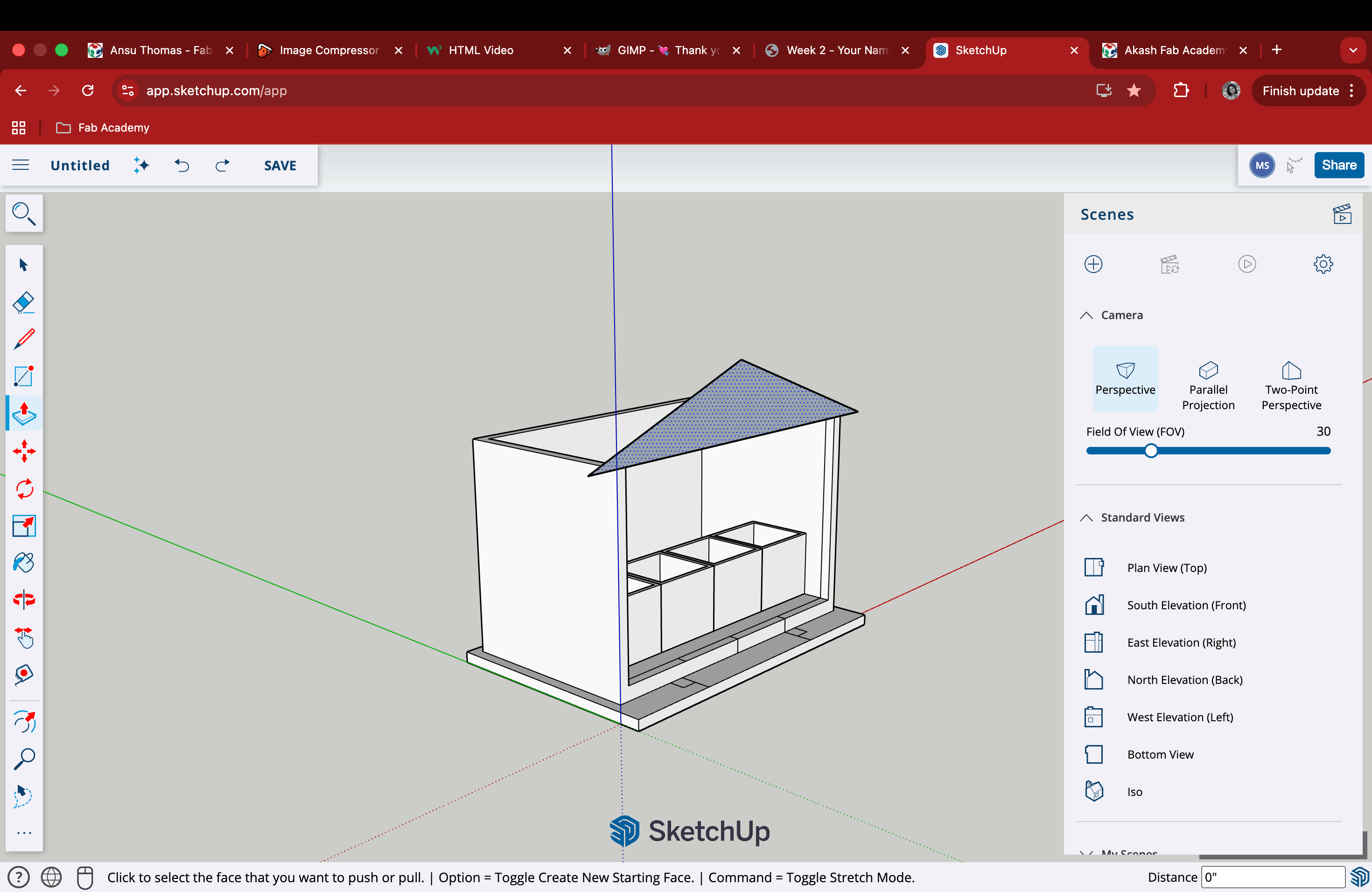
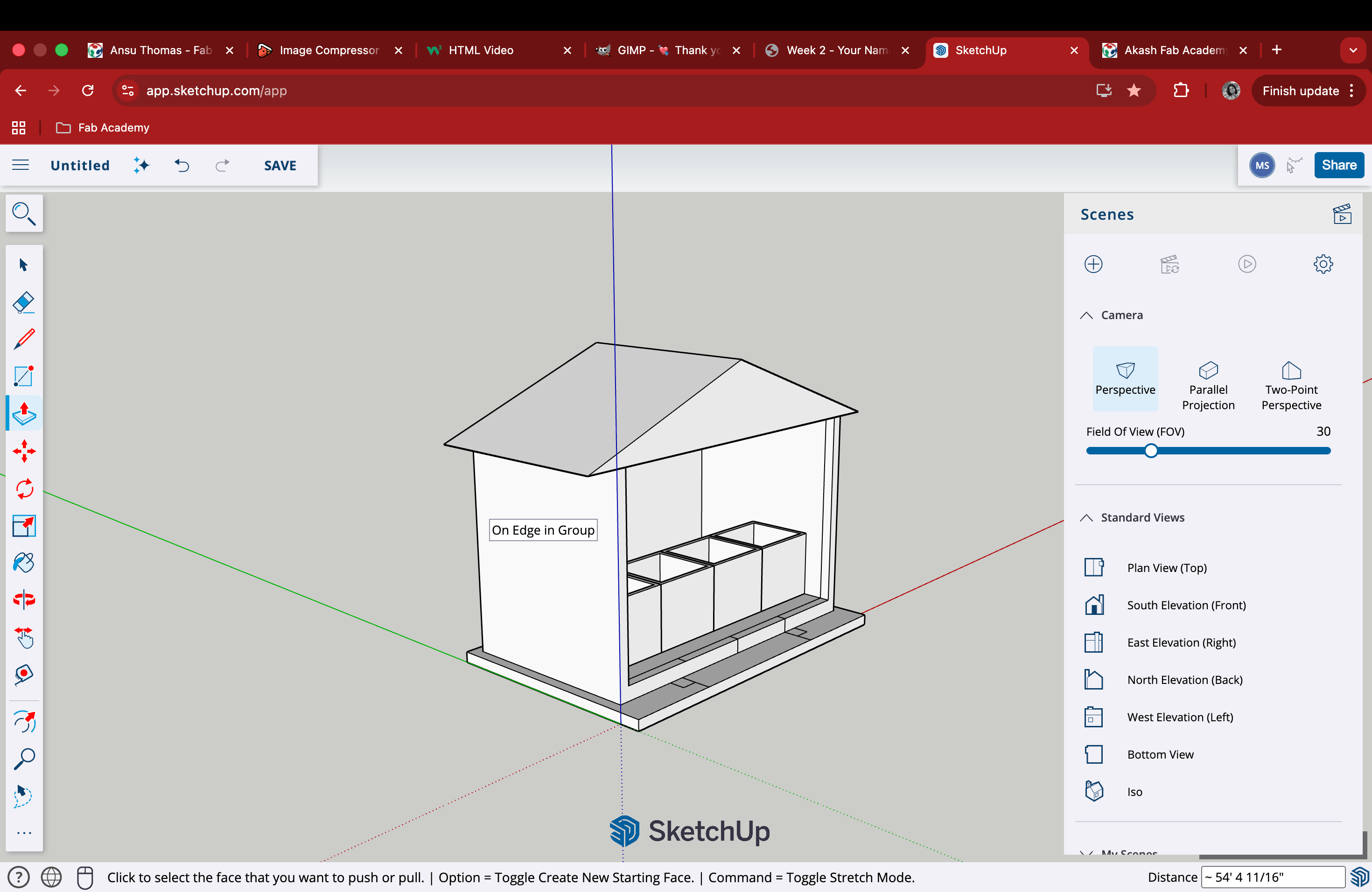
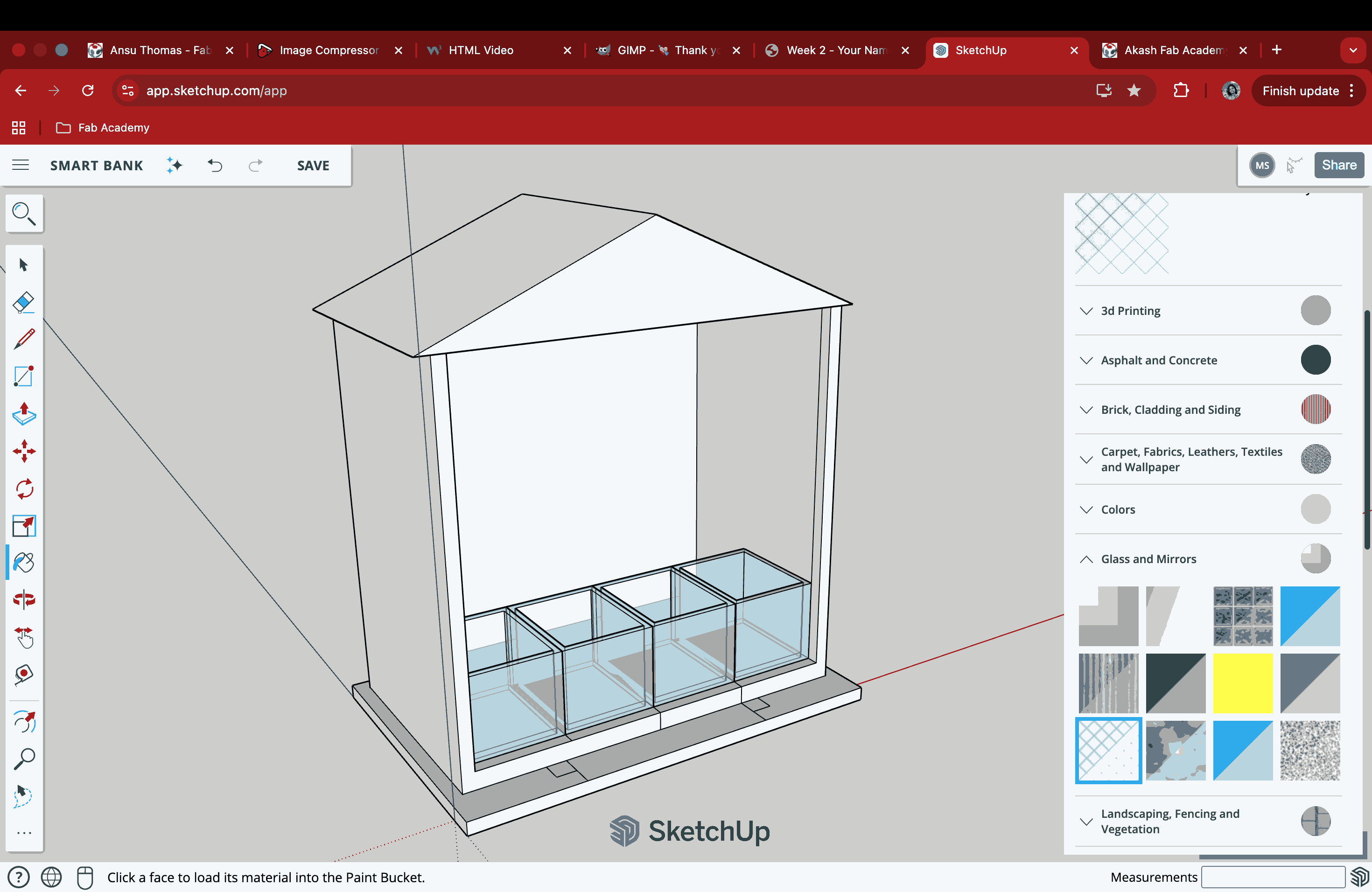
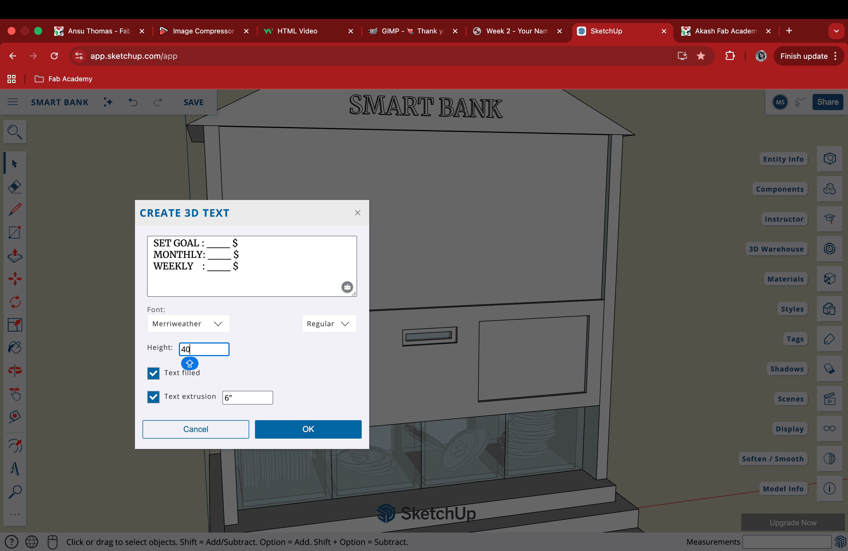
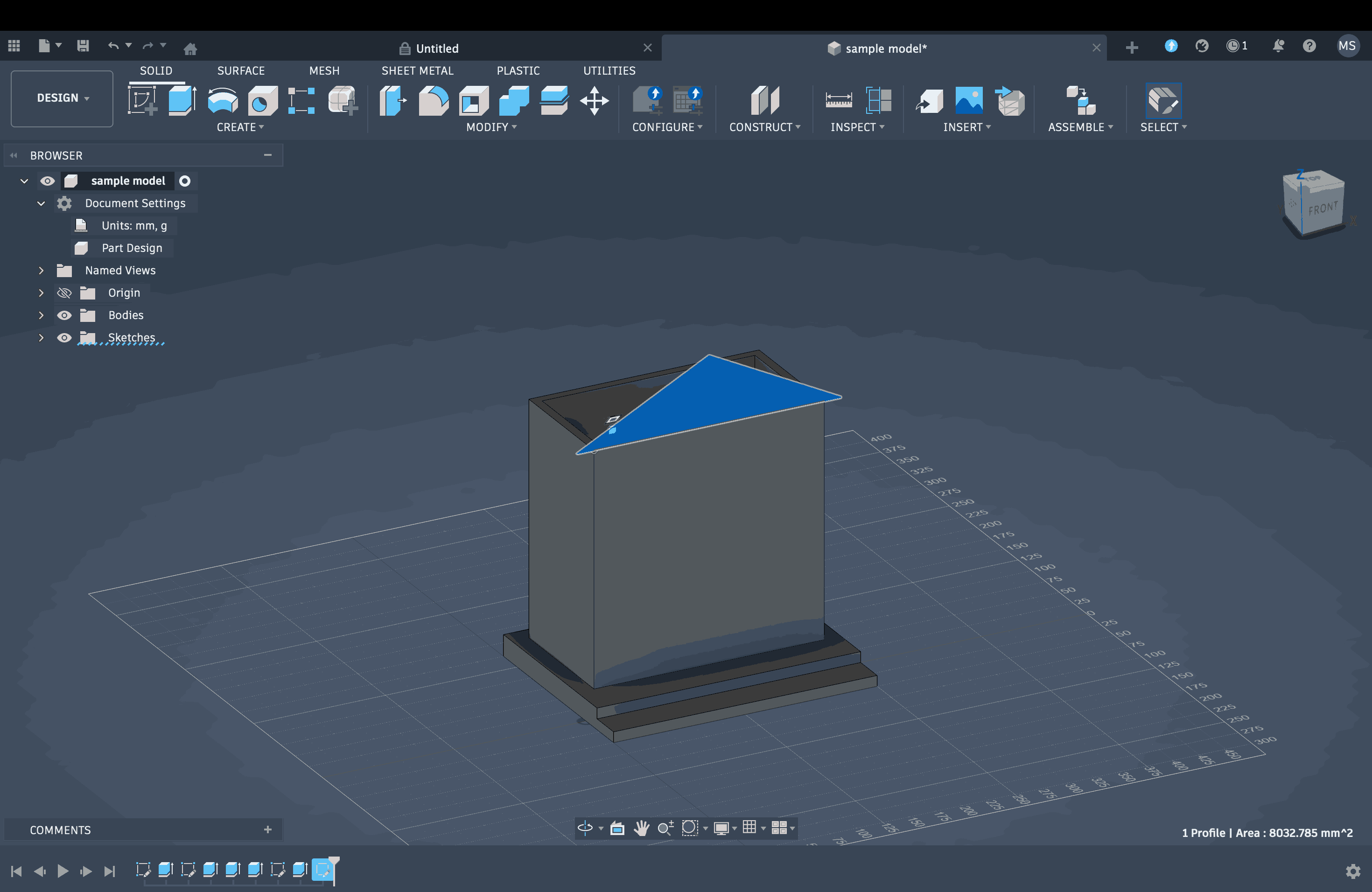
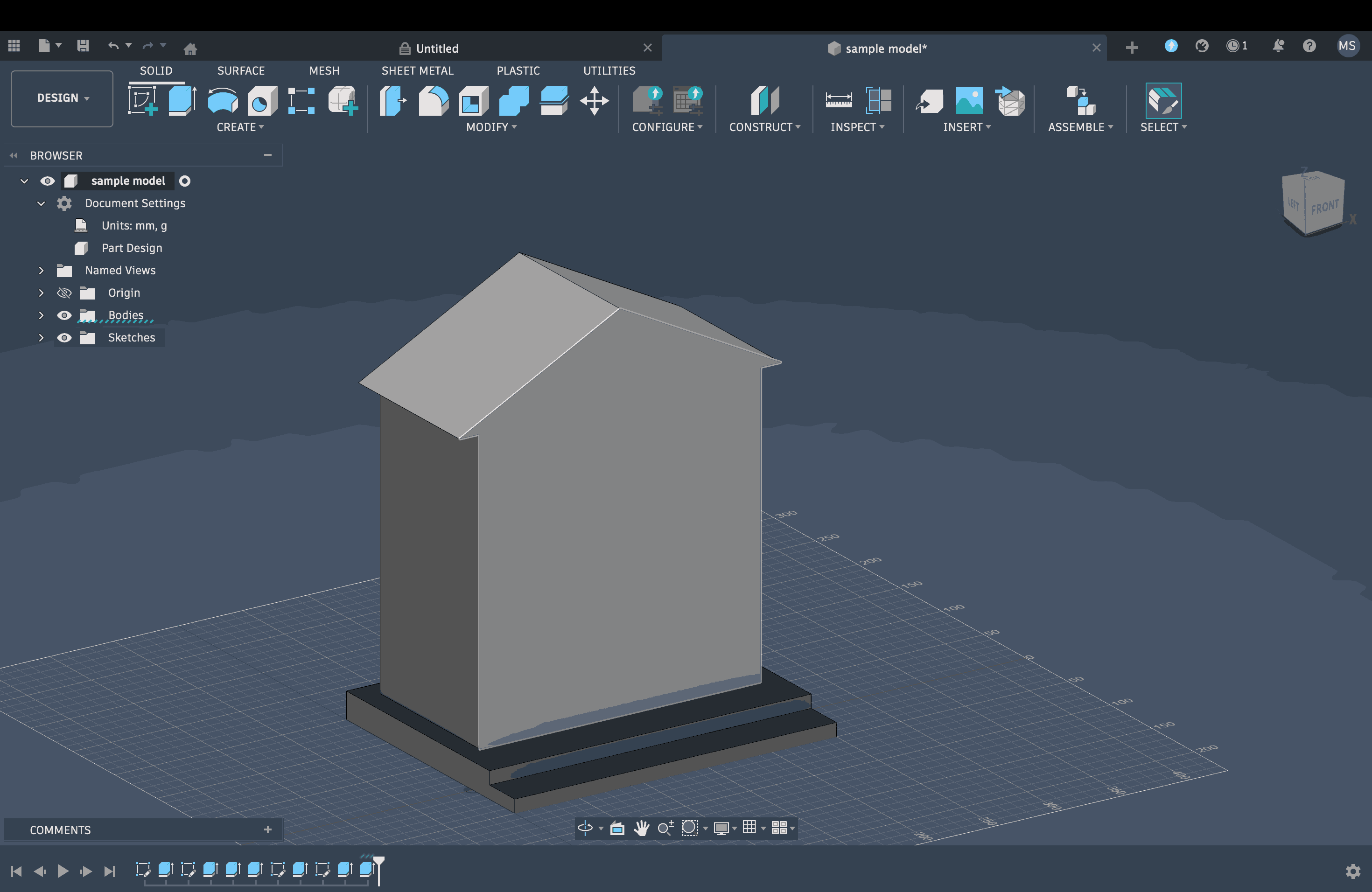
I created a simple triangular roof and extruded it into a prism to cover the area, then added a wall above the container to close off the structure. Once the façade of my little smart bank was ready, I went ahead and added small details using the 3D Text Maker tool. I tried different font options and played with size and scale to get a sense of the right placement. I also made a large dollar sign to place on top of the wall, just below the roof.
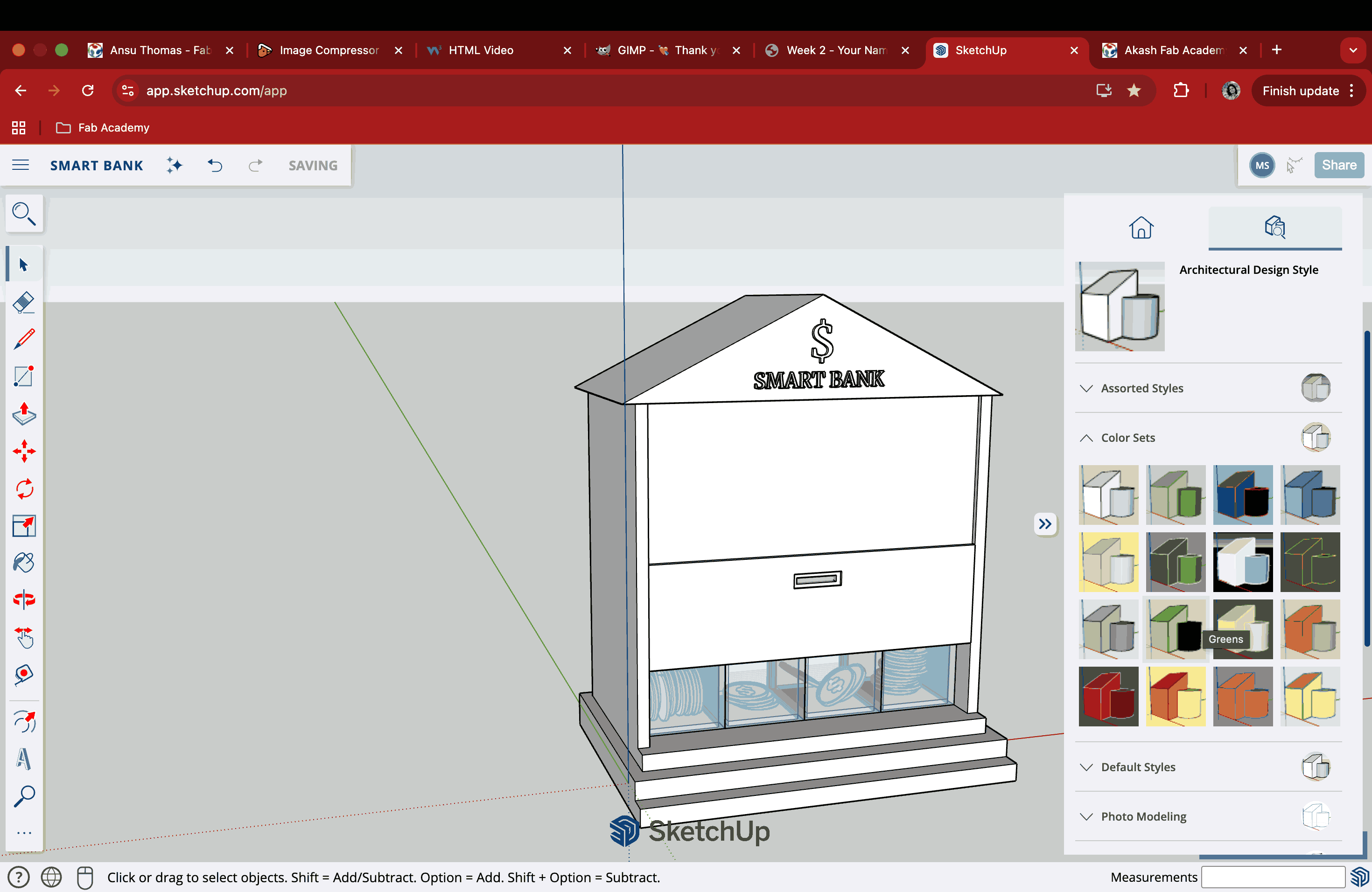
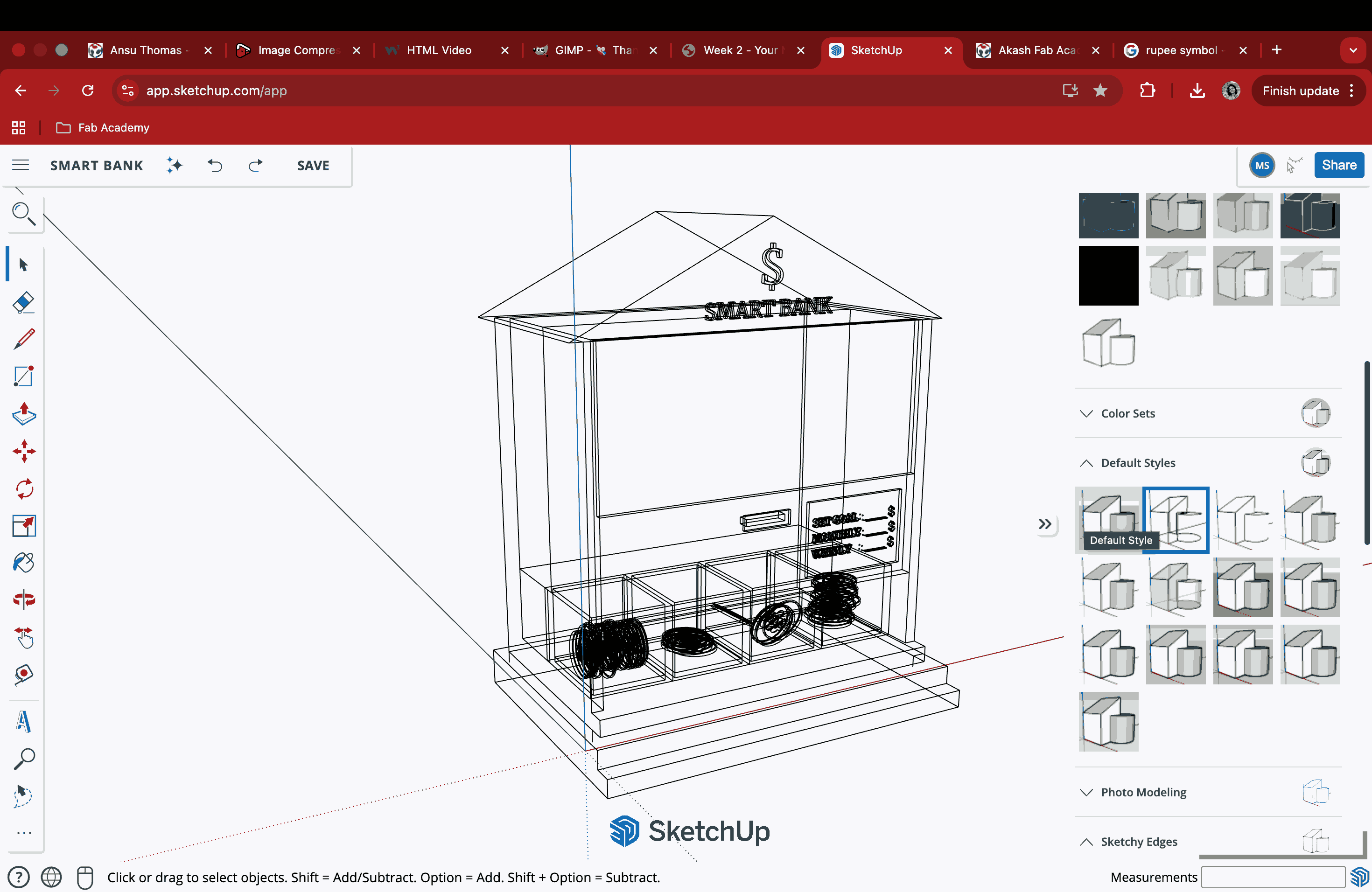
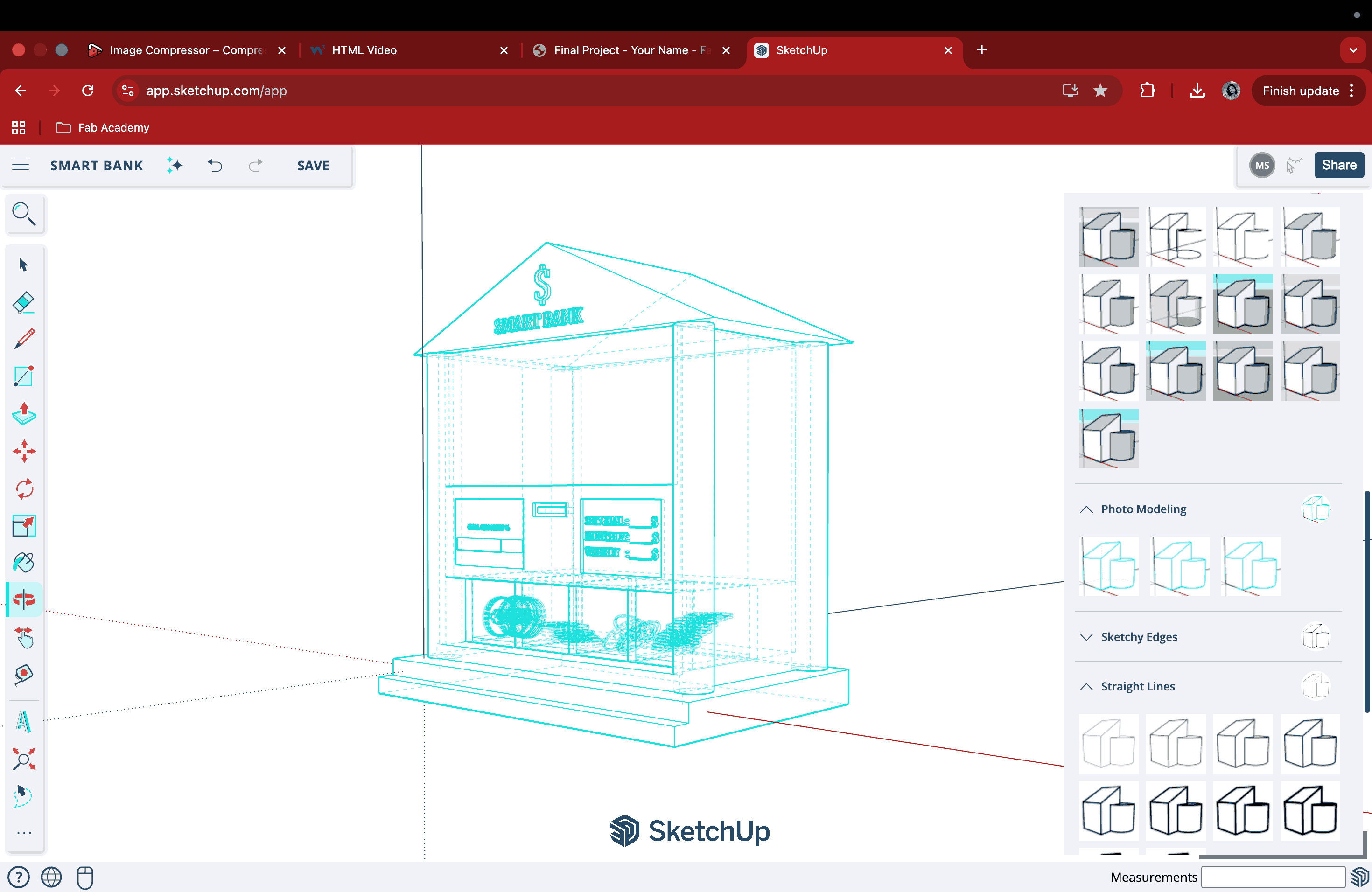
SketchUp has an amazing variety of viewport styles to choose from, including X-ray–like views and sketch-style views. I tried out a few of them to see how I could manipulate the 3D model back into a 2D concept sketch. I also managed to screen-record a short video to show the sketch-like 3D effect that can be generated in SketchUp. Another reason I was able to approach the structure in this way is my background in architecture, which makes thinking about and building forms like this feel more natural to me.
Rhino
Robert McNeel & Associates created Rhino 3D, also known as Rhinoceros, a professional-grade 3D computer graphics and computer-aided design (CAD) program. Rhino employs NURBS (Non-Uniform Rational B-Splines), as opposed to the majority of modelling programs that use polygon meshes, which can appear "jagged" up close. This mathematical model provides precise, smooth curves and surfaces required for real-world manufacturing.
I had previously used Rhino for a short period and hence the interface felt familiar although I had forgotten most of it. I downloaded a 90 day free trial version this time to explore and brush up 3d modeling.
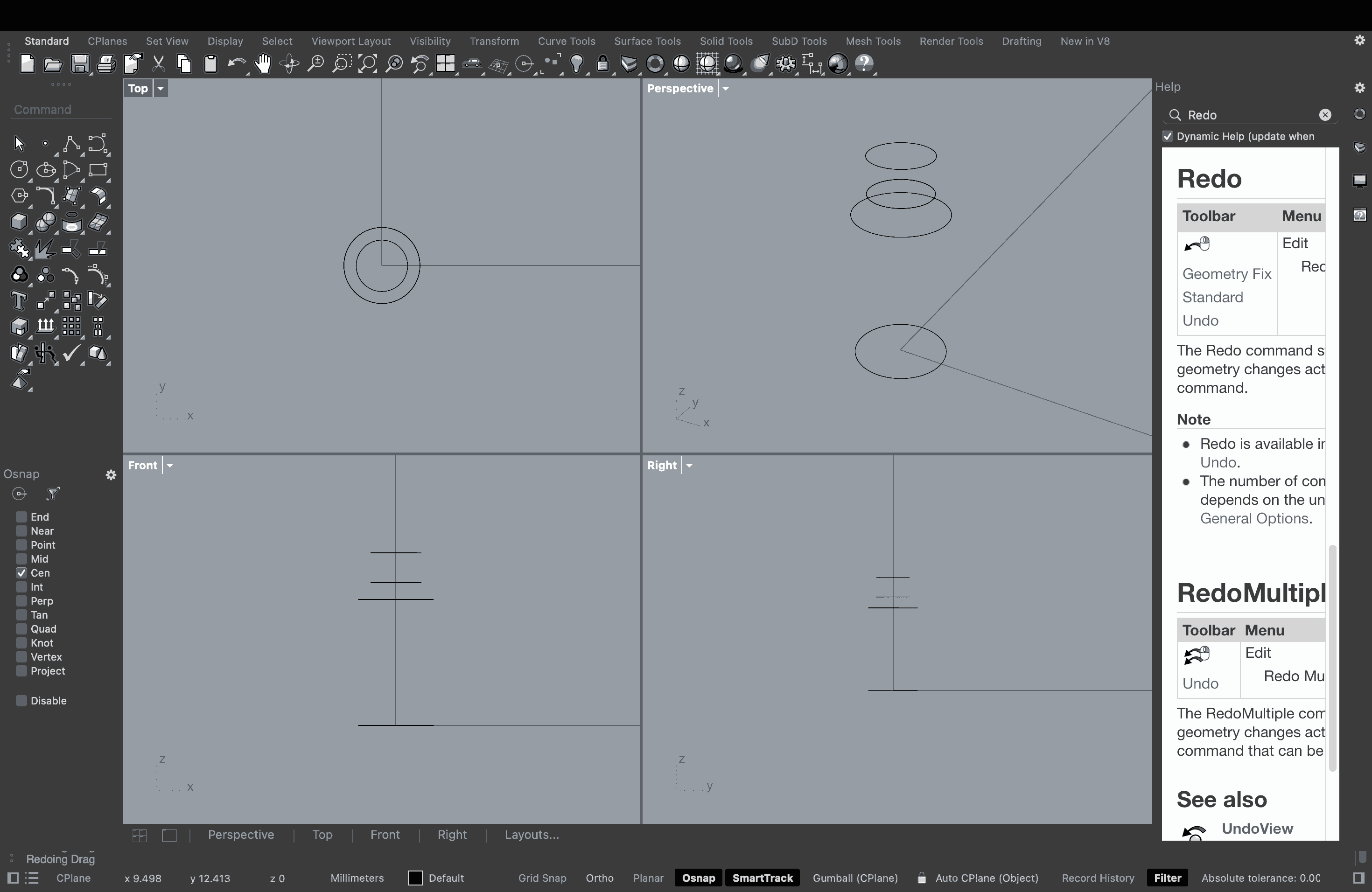
The interface of Rhino comprises four quadrants that show the Top view, Front view, Right view, and Perspective view. What I tried doing here was to make a vase using Loft, since that was the command I recalled first. The Loft command in Rhino provides a smooth surface that fits through a succession of chosen profile curves. It is among the most basic surfacing tools for switching between various cross-sections or forms. I drew a circle in the Top view and then made a copy of it. Then, I selected the copied circle in the Front view and moved it upwards to position it at the height I required the vase to be. I repeated this method while scaling the diameter of the circle to create a narrow neck and opening. The idea was to create this frame around a central axis so that the Loft method could be utilised later.
Once I had the circular framework ready along the central axis, I typed in the Loft command and the cursor changed to select the points required for this action. Points along the central axis were selected, and a wireframe of the vase was created in the viewport, while a shaded model was shown in the Perspective viewport.
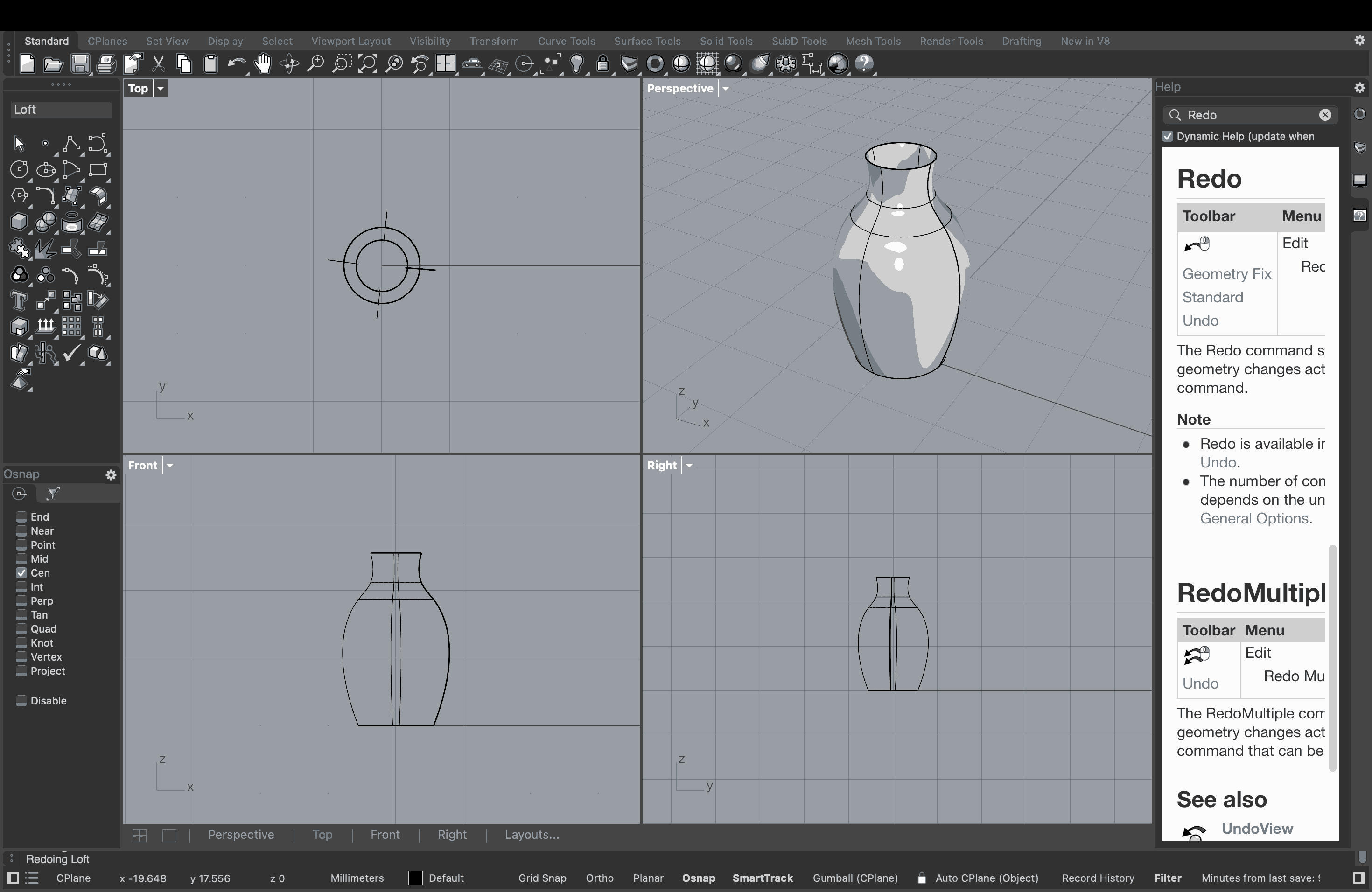
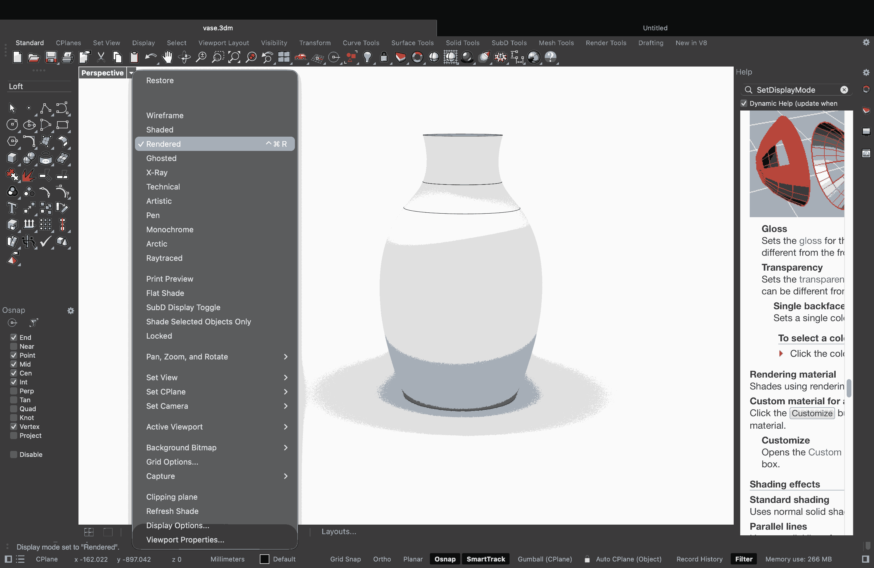
Maximised the PERSPECTIVE viewport and selected the RENDERED option to get the view shown in the image above.
Blender
Blender is a free and open-source 3D development package that covers the full 3D pipeline. It’s used by everyone from individual hobbyists to large studios for modeling, animation, rendering, and visual effects. When it comes to modeling and sculpting, Blender has a ton of tools for both polygon modeling and digital sculpting. You can create anything from simple objects to really detailed characters. For animation and rigging, it also has some powerful features like skeletons and automatic skinning, which are used in award-winning short films.
Blender was difficult. It made sense in the very beginning, but pretty soon I felt a kind of brain fog. Whatever the instructors said felt like it was bouncing off my head instead of actually going through it. Blender is an amazing software-why? Because I saw an Academy Award-winning animated movie (Flow) that was made using Blender. But honestly, I still have no idea how it works, why it works, or how to make it work.
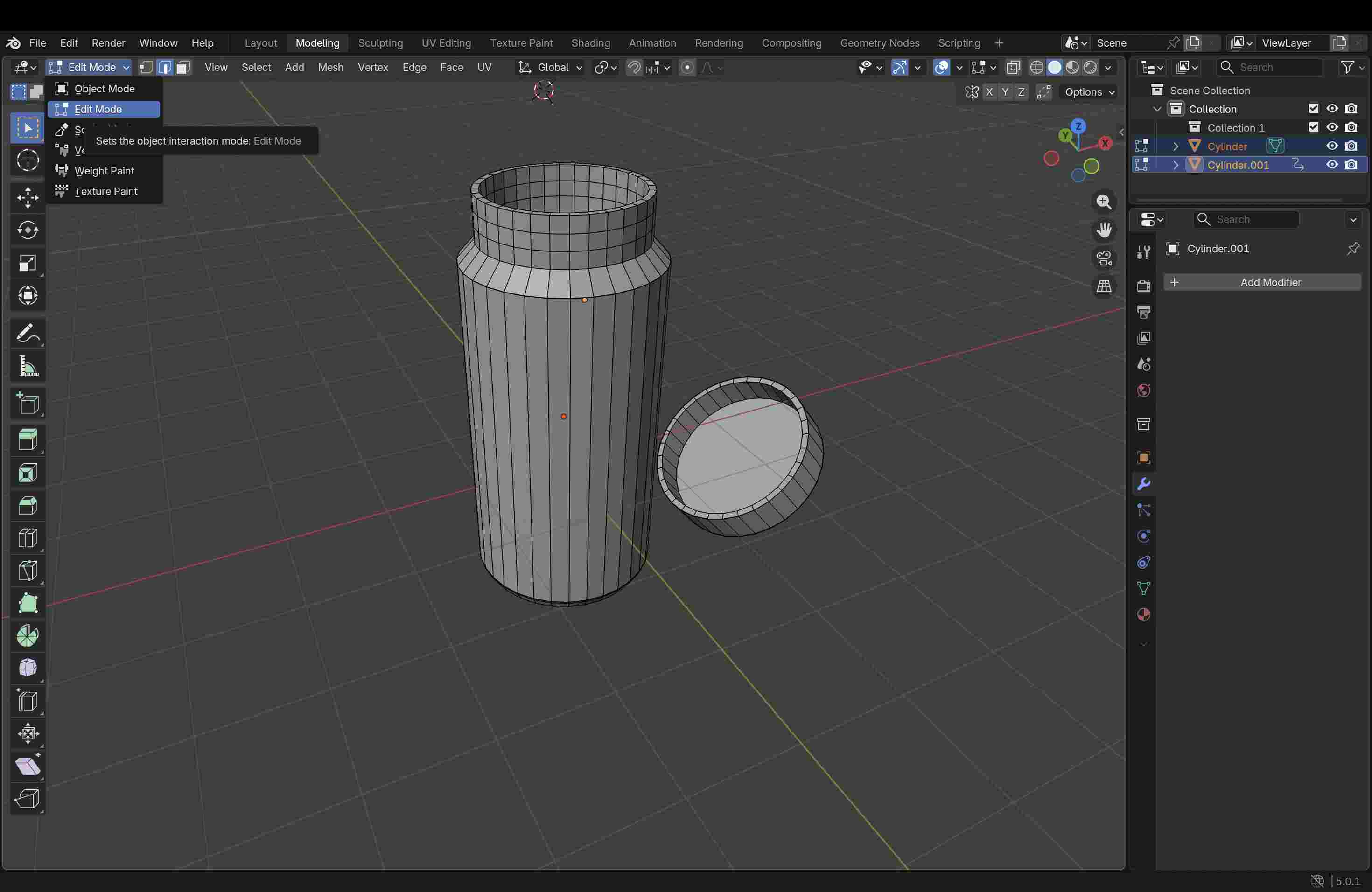
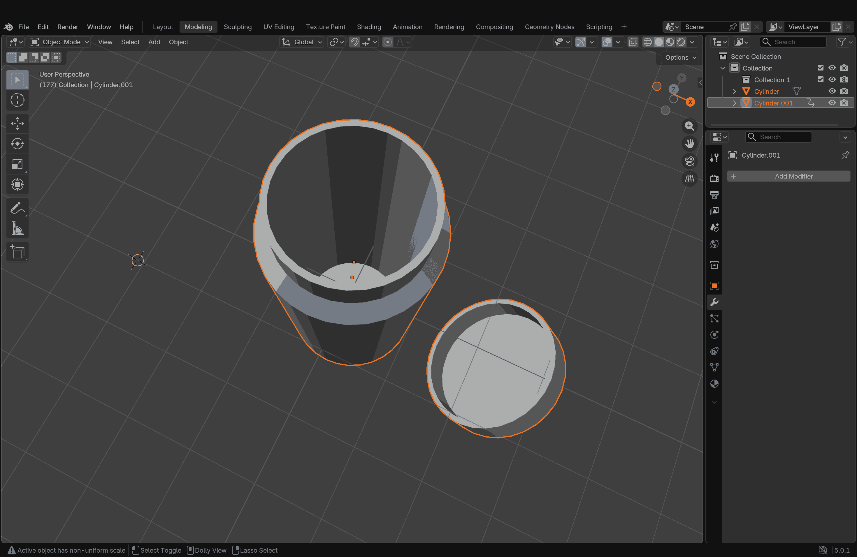
From our little exploration, this is what I understood so far: there is an Object Mode and an Edit Mode. You create objects in Object Mode, but to edit them, you switch to Edit Mode. If you create new objects or copy something while in Edit Mode, those objects somehow end up being linked. So, if you want your copied object to behave independently, you need to come out to Object Mode first. How do I know this? I made that mistake. But there are fixes for it too.
Blender also allows animation. I tried to sculpt a bottle and its cap, made them as separate objects, and wanted to show the bottle cap flying off or falling down from the top. At least, that was the idea. I tried following the instructions, but I got completely lost midway and couldn’t even complete the task.
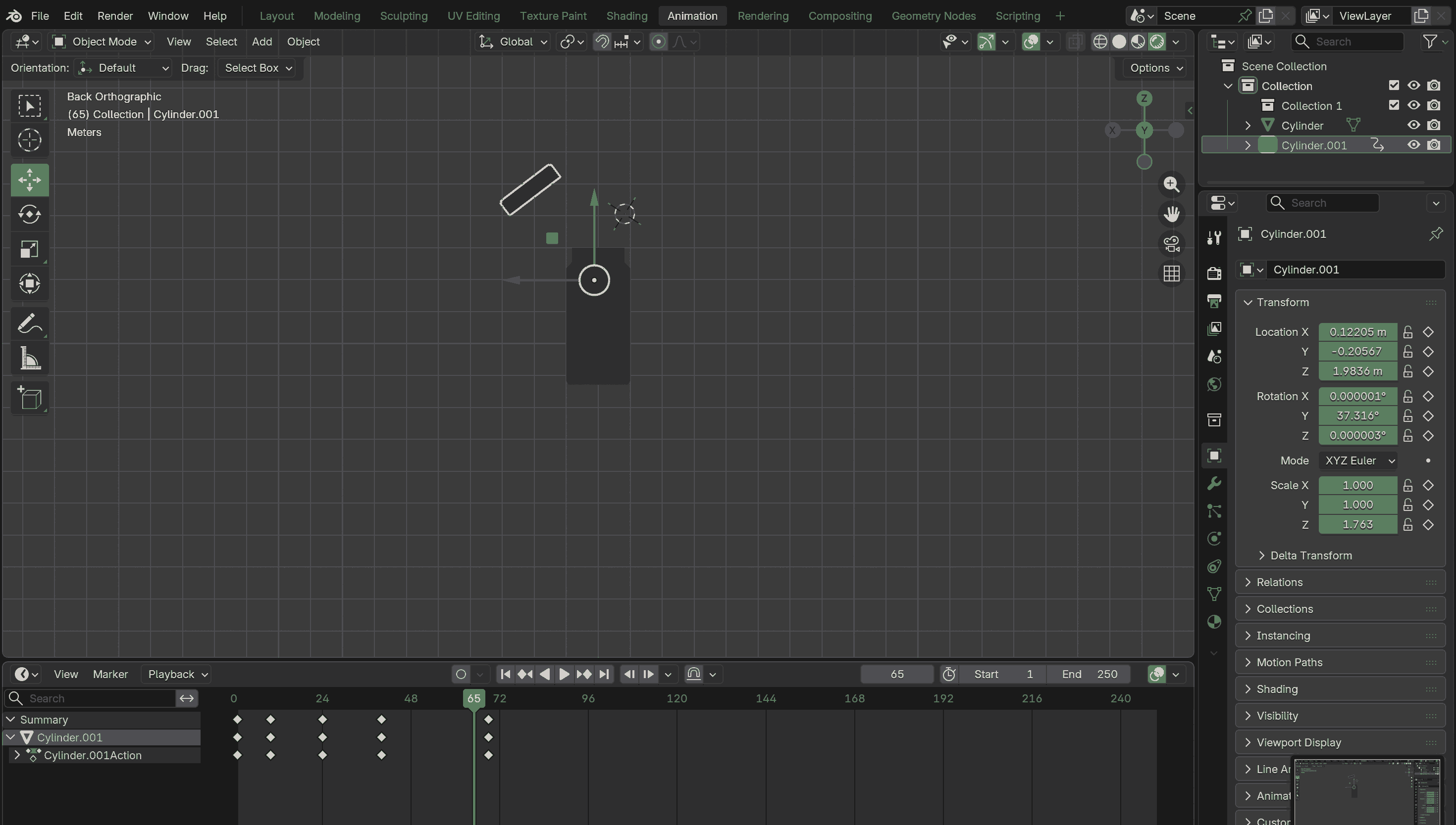
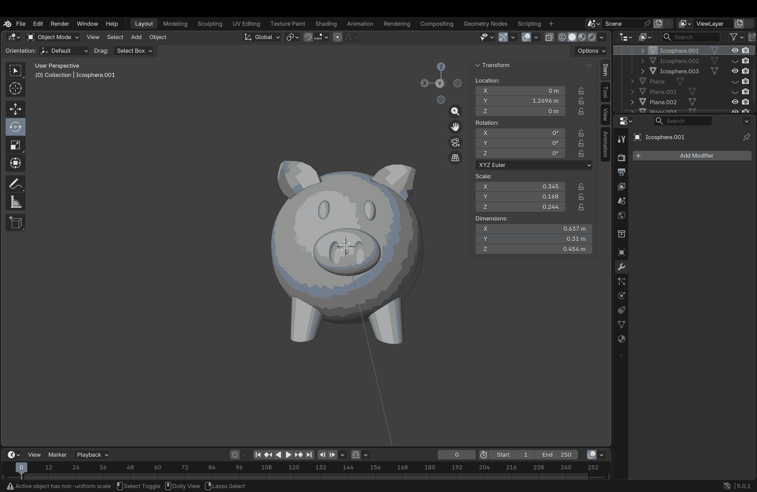
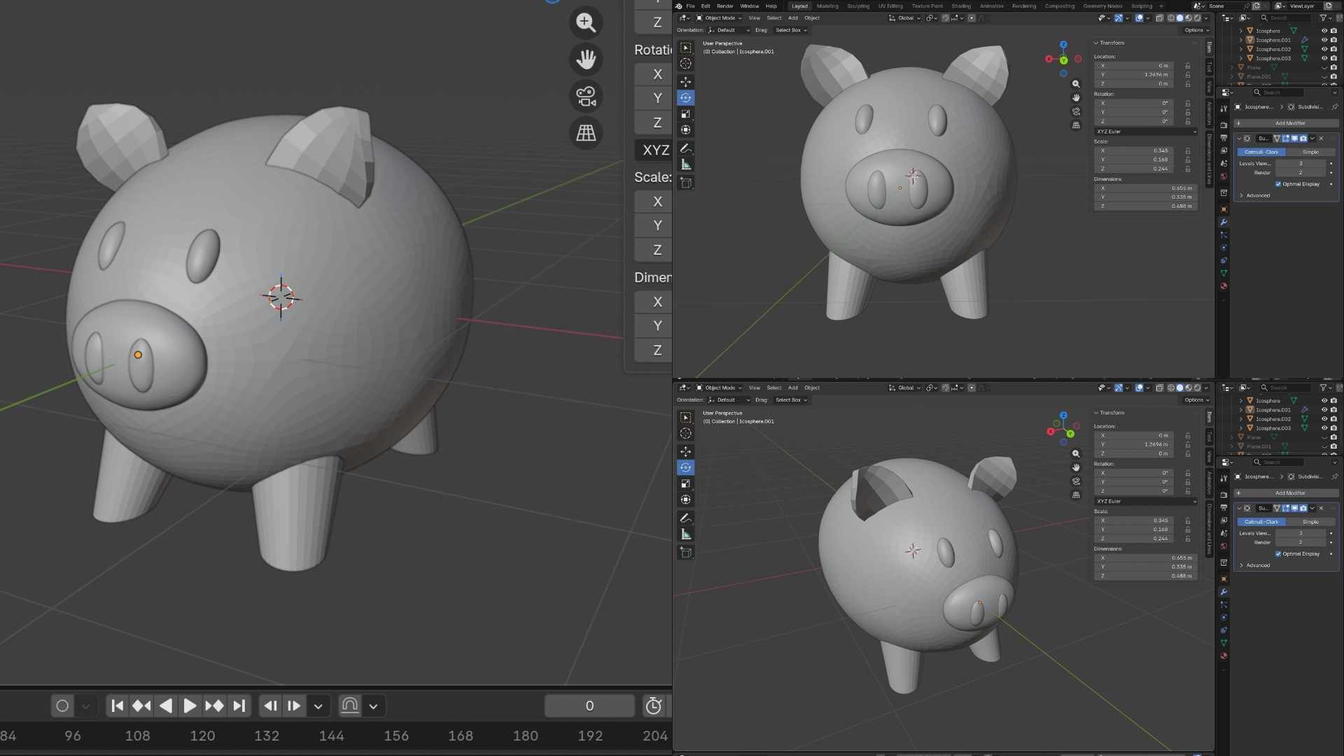
Later, one day, Rico explained Blender again and gave us a quick 10-minute tutorial, and he made it look so easy. I was genuinely impressed. Now I really want to give it another try. During the regional review, Rico also commented on my final project model and suggested that the piggy bank for kids would be more fun if it maintained a traditional look with modern technology integrated. I took this opportunity to model a piggy bank in Blender with the help of our instructor at Kochi Super Fab Lab.
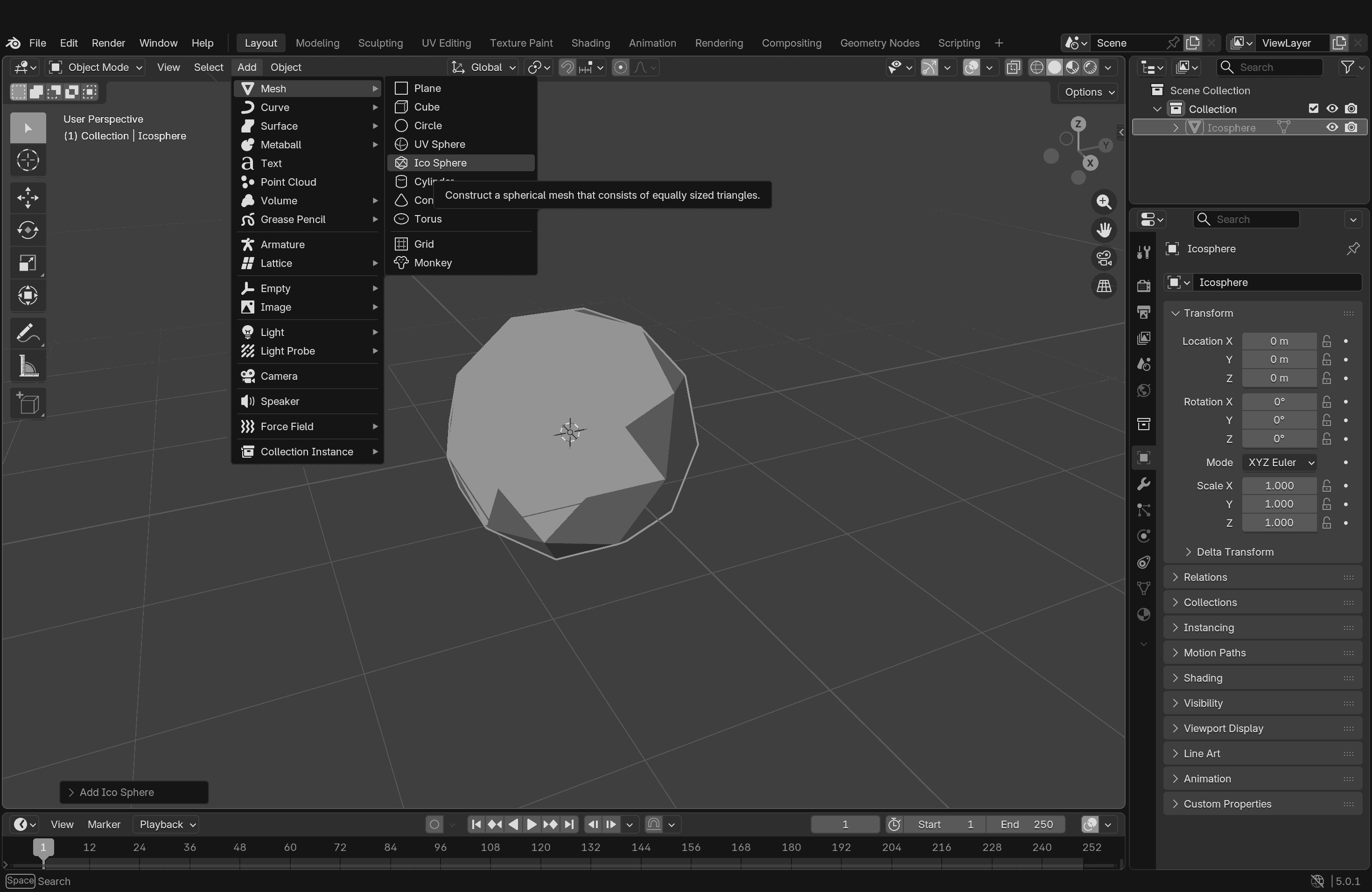
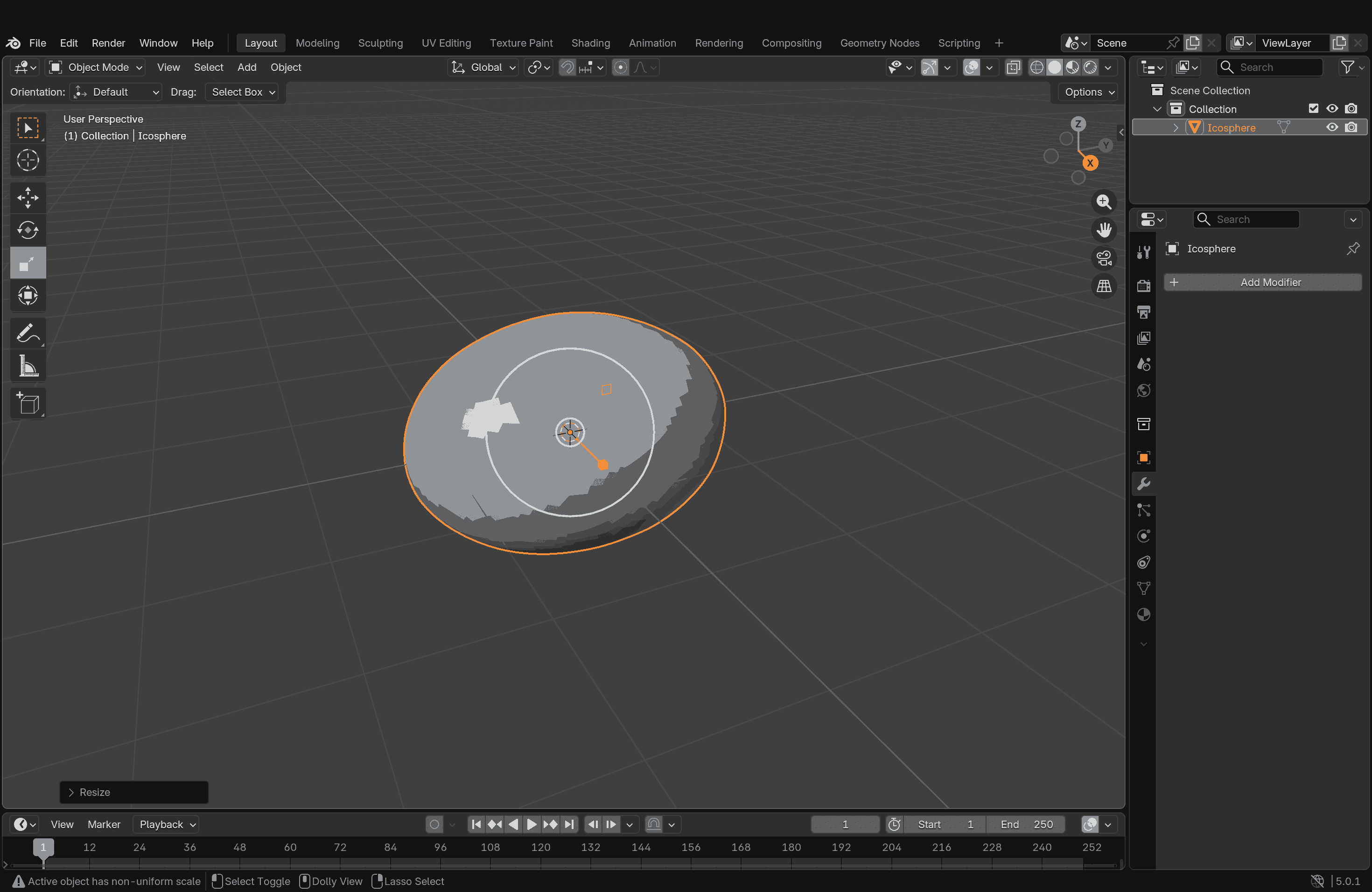
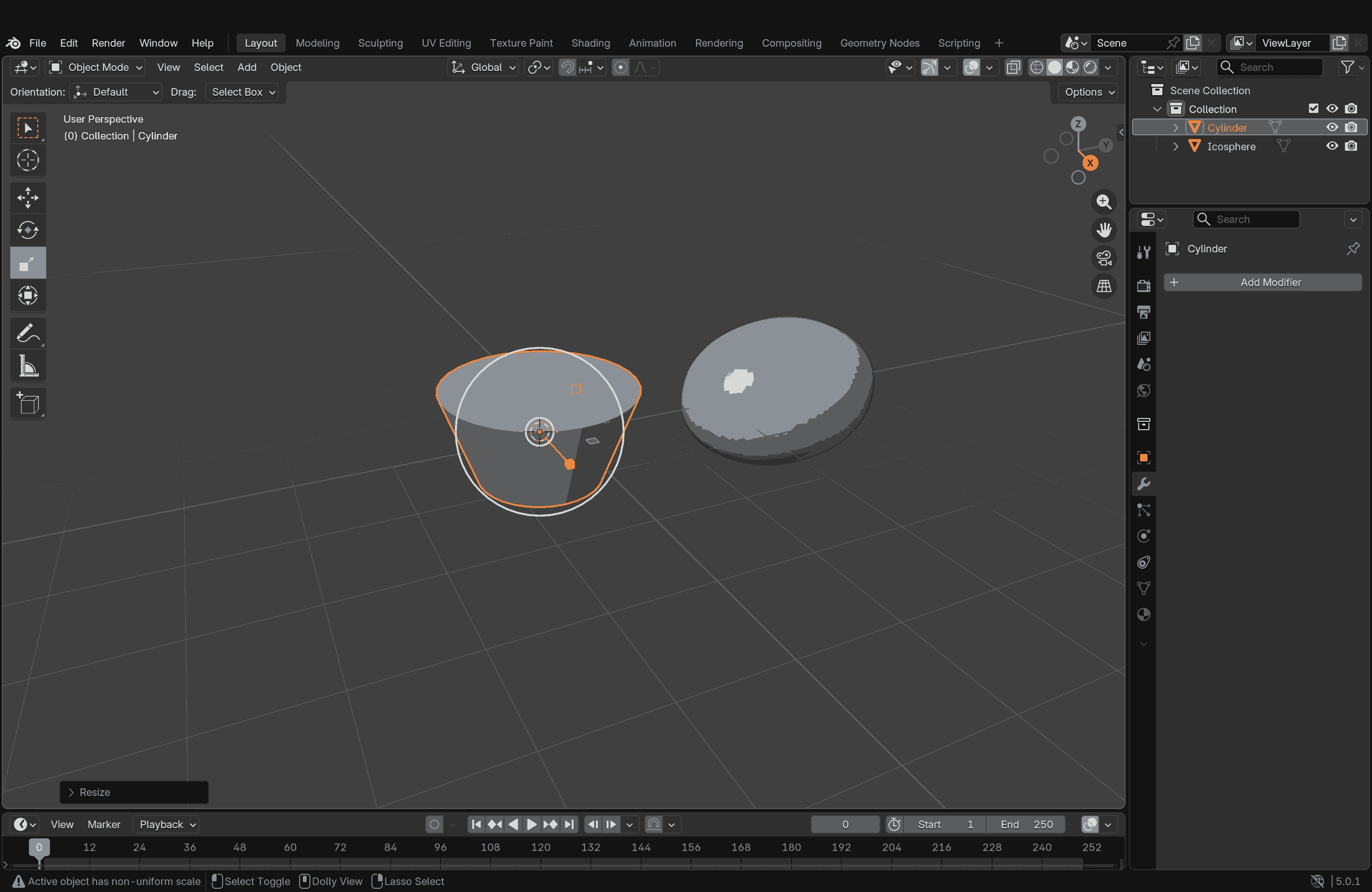
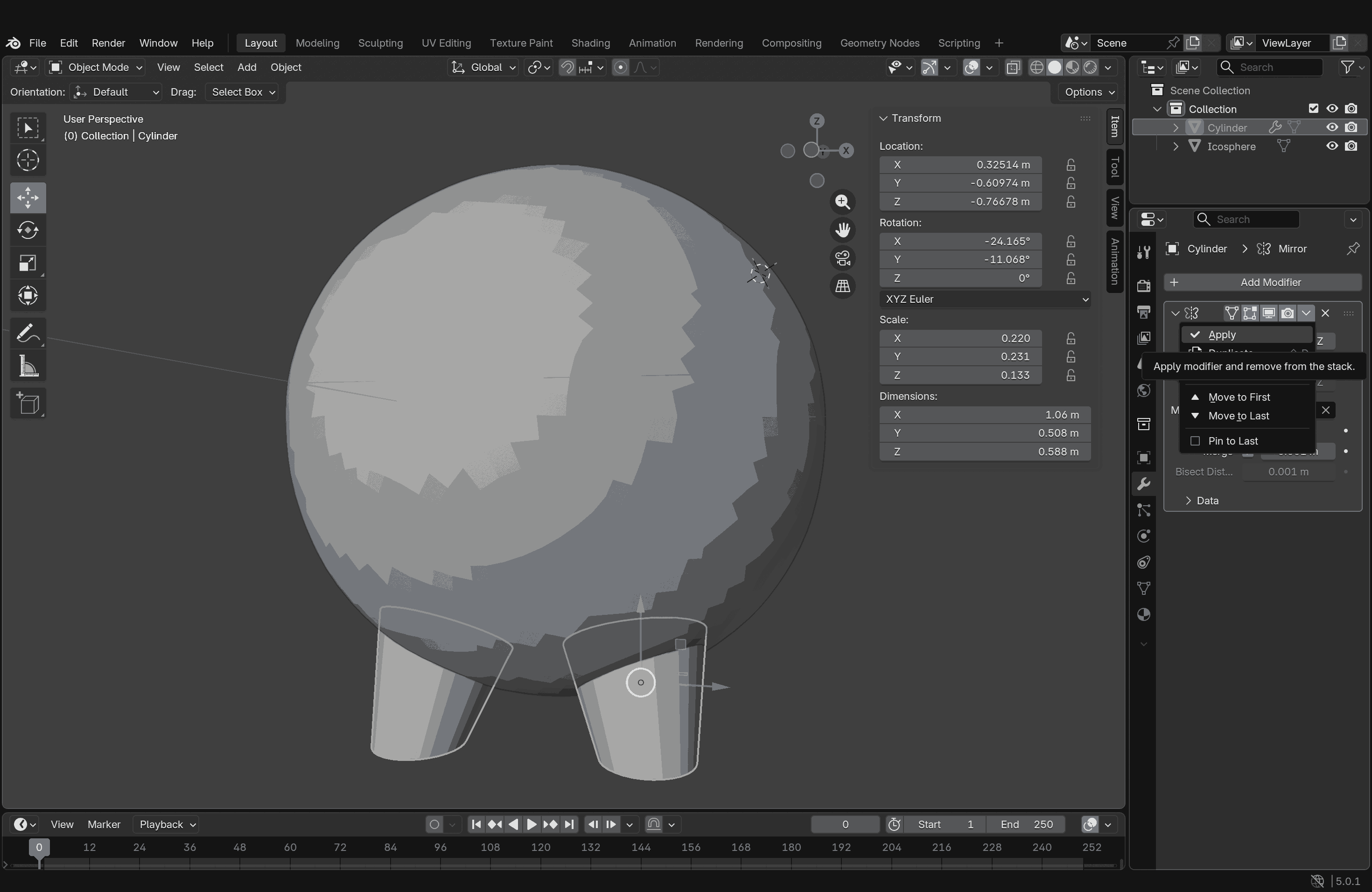
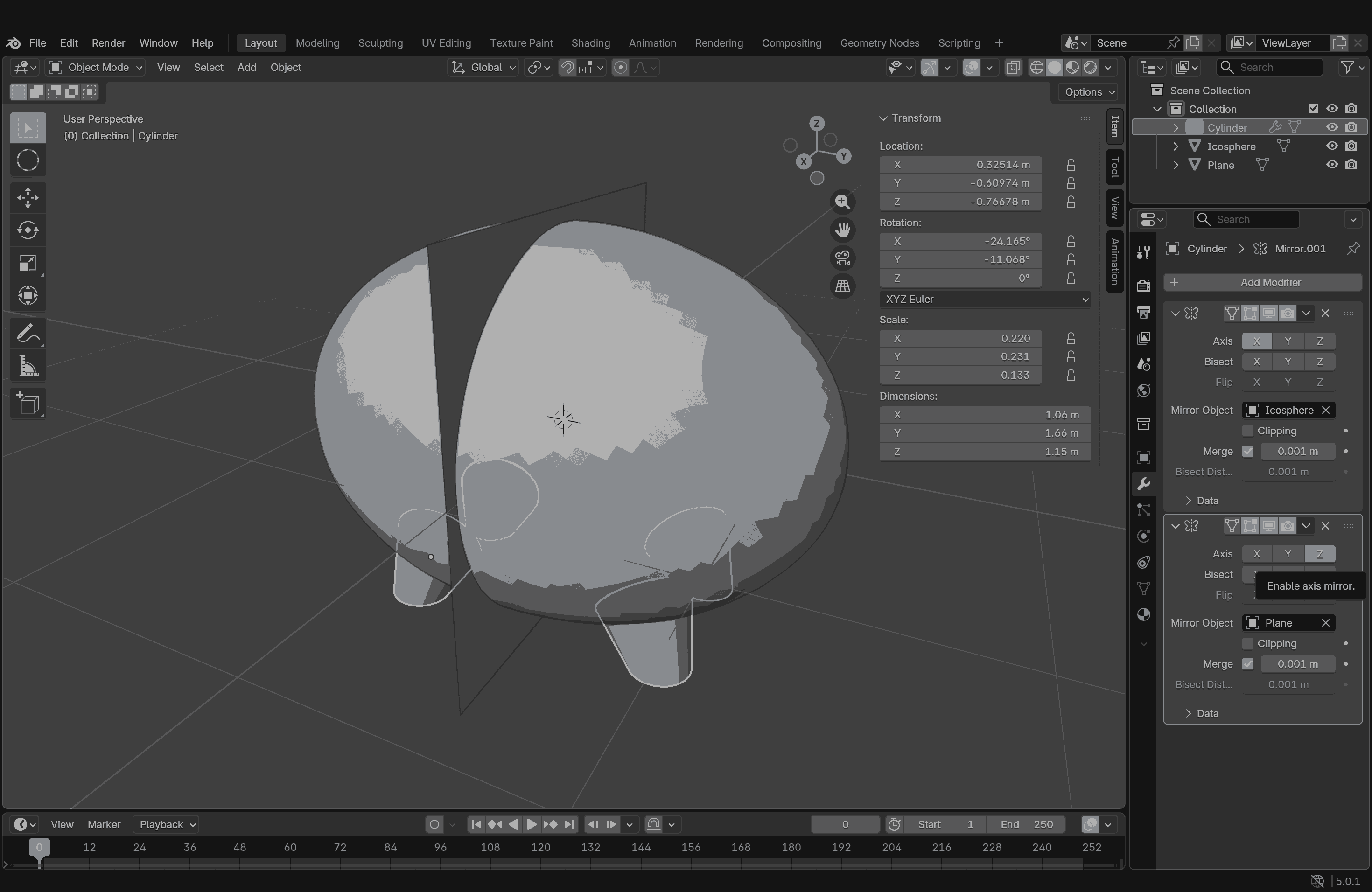
This time, I started with an Ico sphere and subdivided it for a smoother surface. I elongated the sphere along one axis, this formed the main body of the piggy bank. To give it legs, I started with a cylinder and, in Edit Mode, manipulated its diameter on one end to make it narrower, then scaled it down to match the piggy bank leg profile. Once I finished one leg piece, I used a Mirror modifier to replicate the second leg, keeping the main body (the elongated sphere) as the mirror object.
To replicate the back legs, I had to draw a plane and use it as the object reference for mirroring. Once all four legs were positioned correctly, I applied the modifier.
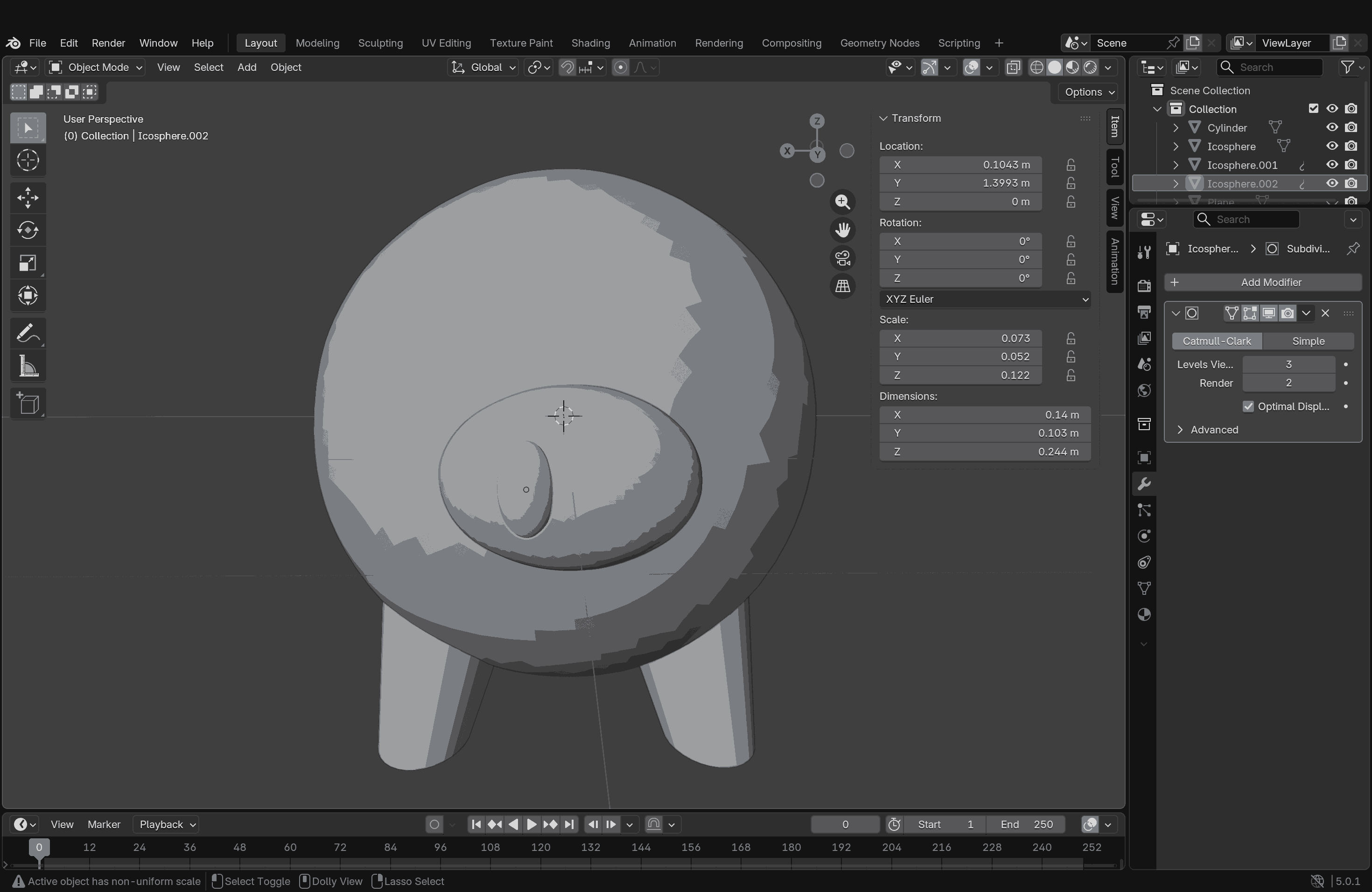
After this, I moved on to creating the nose, nostrils, and eyes, all using manipulated icospheres-mostly using the Scale tool—and then did a Boolean operation to subtract them from and add them to the main body.
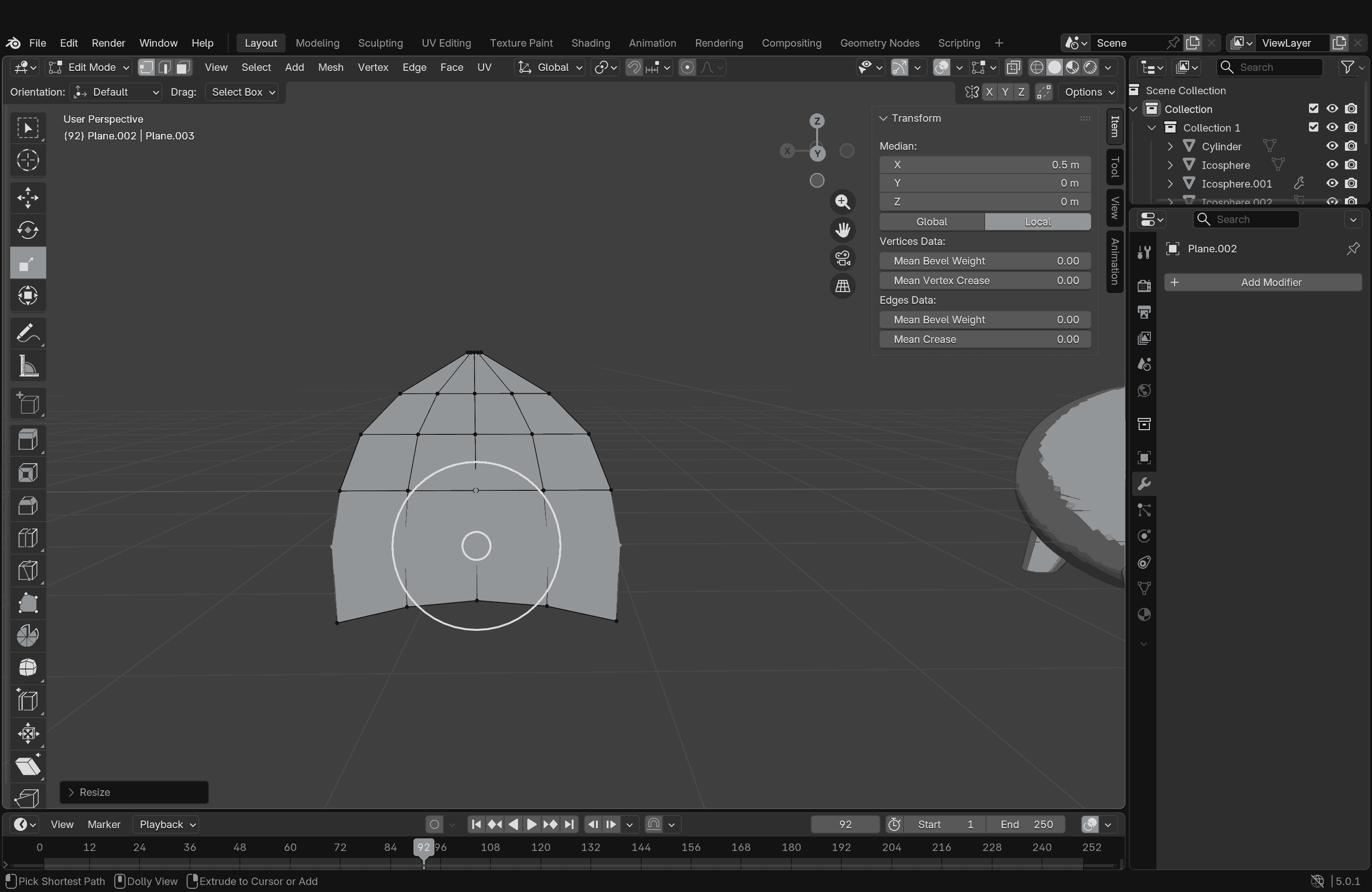
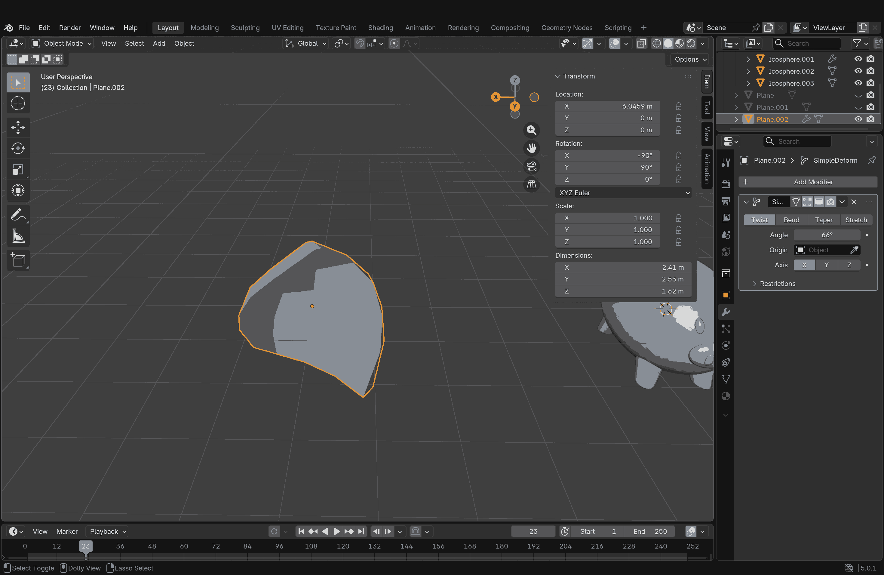
The tricky parts were the ears. I didn’t want them to look very static and wanted some organic flow. After playing around with a few Deform modifier options, I settled on the Twist Deform option applied to a plane that I manipulated and extruded. It worked well; a copy was made by mirroring and placed on the head.
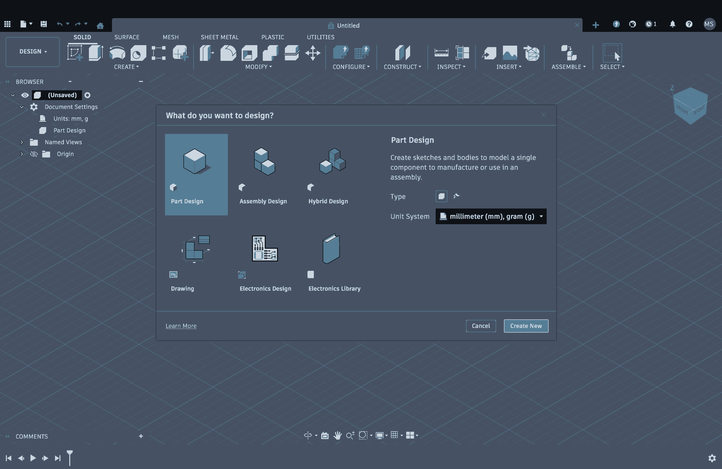
Fusion 360
Autodesk Fusion (formerly Fusion 360) is a comprehensive, cloud-based platform that combines CAD, CAM, CAE, and PCB software for 3D product design and manufacturing. It enables parametric modeling, simulation, and collaborative workflows from design to 3D printing or CNC machining. It is widely used for professional engineering, with a limited free version available for personal use.
This was my first time using Fusion, and so far, I have a love-hate relationship with it. The interface looked very familiar, but the way it worked gave me a headache at first. Slowly, some things did start to make sense, but I am not fully comfortable with it yet. While I truly understand that no software can be learned overnight, and that it takes a certain amount of time, effort, and practice to become proficient at anything, I am looking forward to learning and practicing more with it.
I had already tried sketching my final project model on paper and on SketchUp first, so I had a better idea of what I was trying to replicate in Fusion, even with my bare minimum knowledge of how this software works. The interface is actually quite self-explanatory, but the whole body-sketch-solid relationship is still confusing to me. I still haven’t figured out how layering works or how to move between things seamlessly. Some options feel very limiting or restrictive, but somehow, things still make sense in the end. That’s why I say it’s a love-hate relationship, I don’t fully know how it works yet, but it works for now.
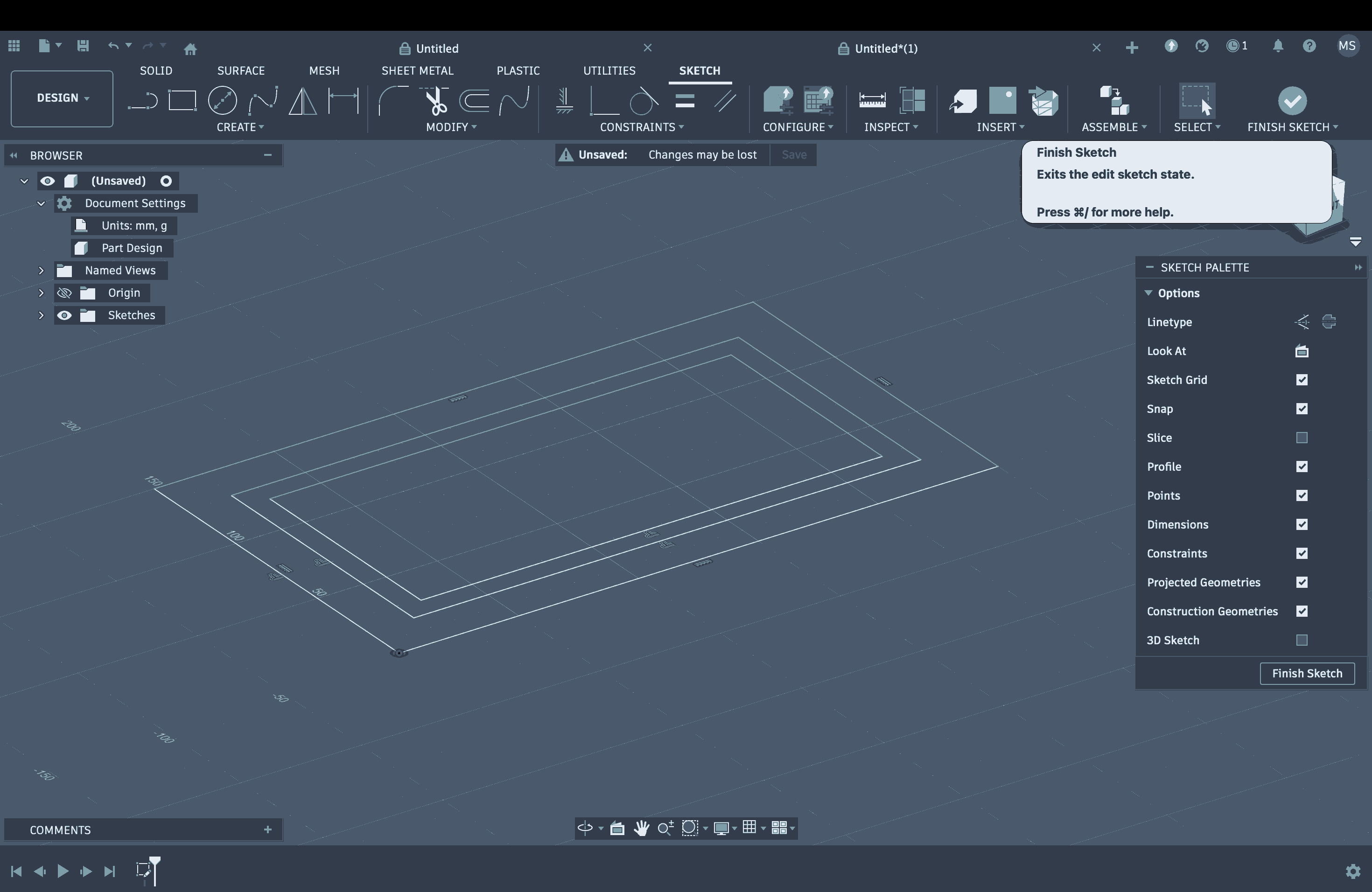
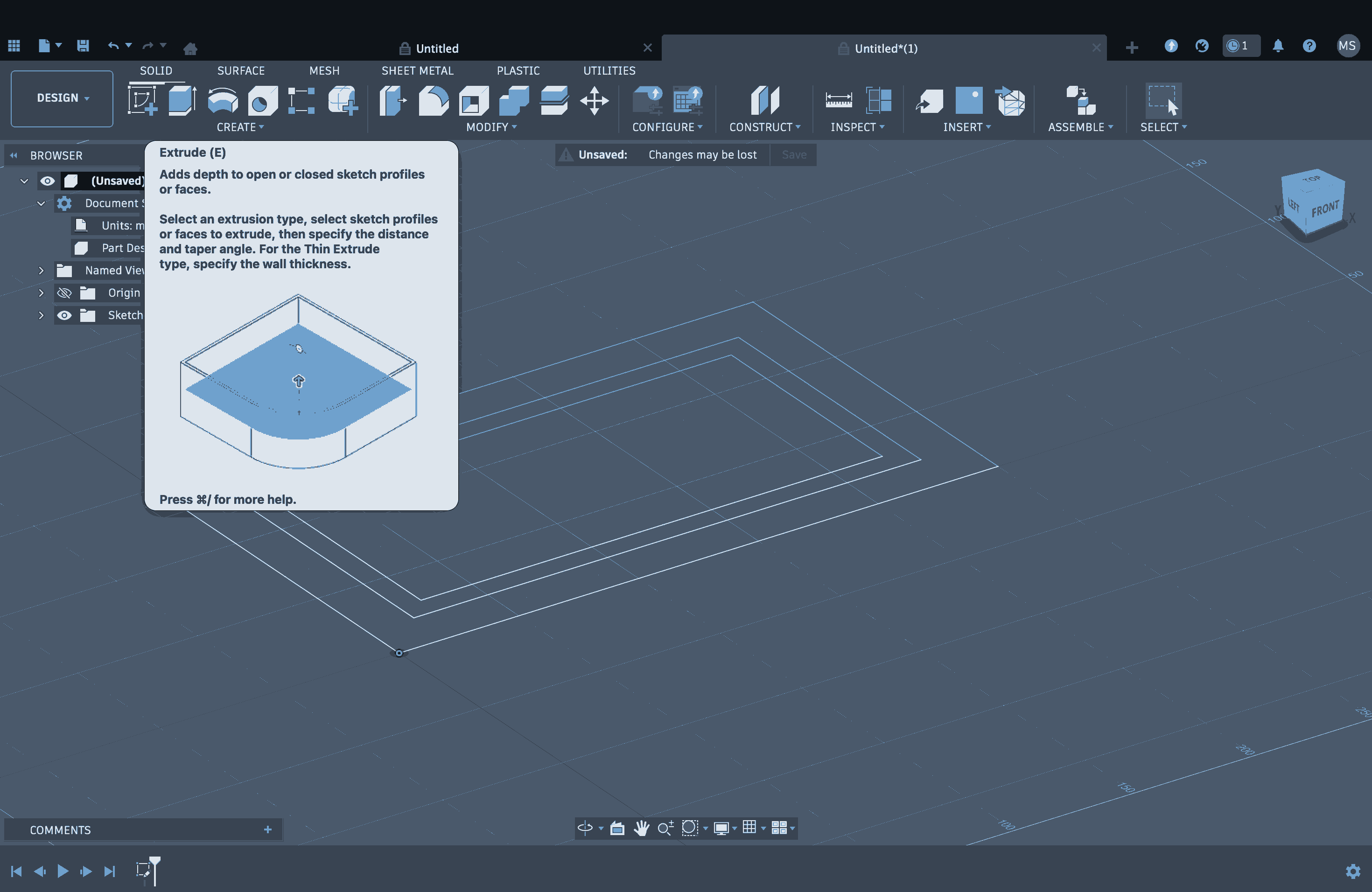
Fusion has various modes such as Design, Render, Animation, and Manufacturing. I worked in Design mode, which begins with creating a sketch, essentially basic 2D drafting. I started with a rectangle for the base of my model, and this is where it got slightly irritating. To extrude the rectangle, you first have to finish the sketch by clicking the tick mark in the top-right corner, and only then are you allowed to extrude it. But I got used to this fairly quickly.
Once you exit sketch mode, the software allows you to extrude. All the tools are displayed in the taskbar above, with clear descriptions of what each tool does and how it works, which appear when you hover over them. To extrude, you can select a surface and pull or push it, adding values according to your requirements.
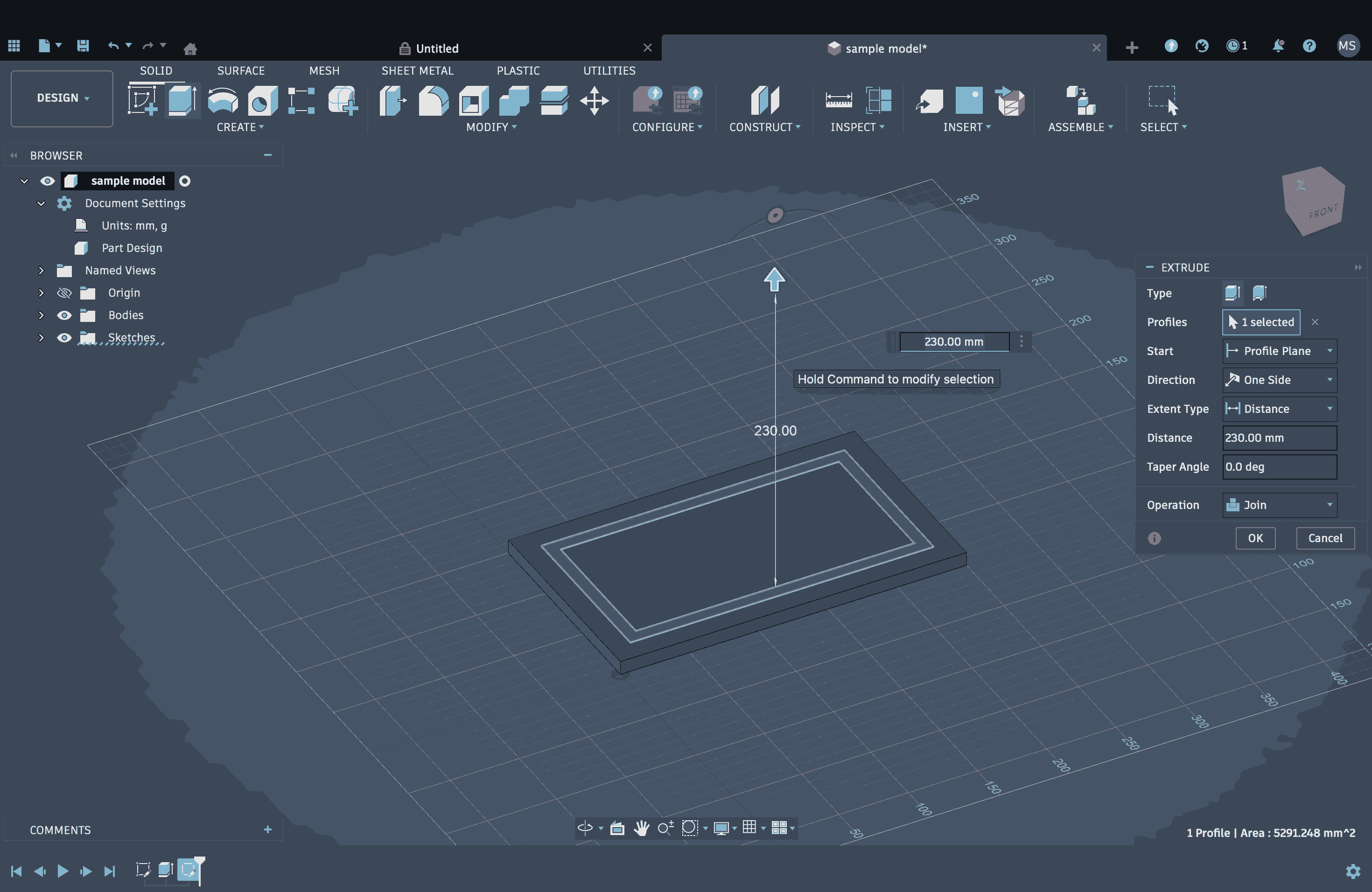
These steps were repeated to create the basic structure. Next, I needed to work on the roof. For this, I selected the Front view, as my plan was to draw a triangle in this view and then extrude it into a prism.
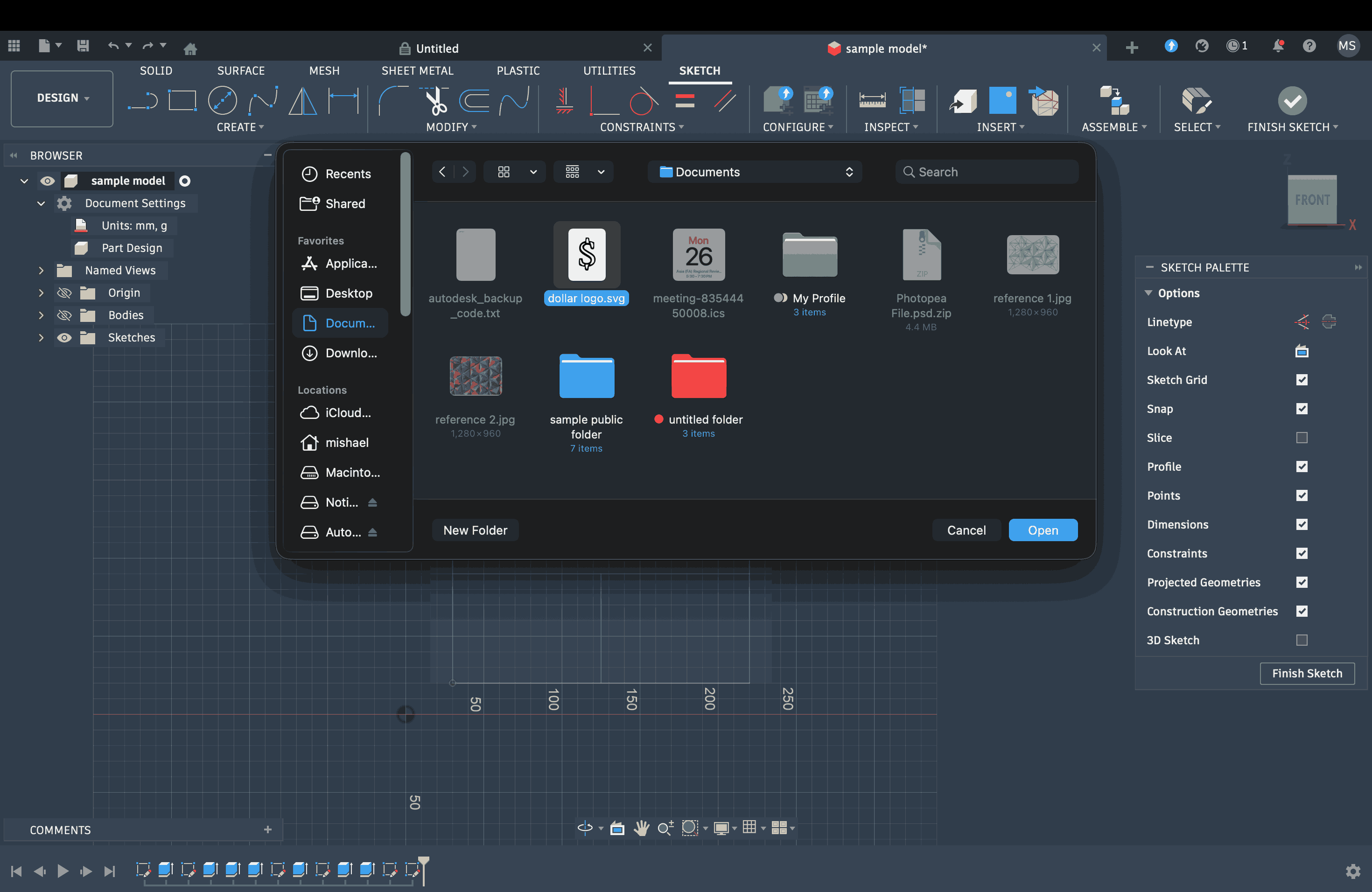
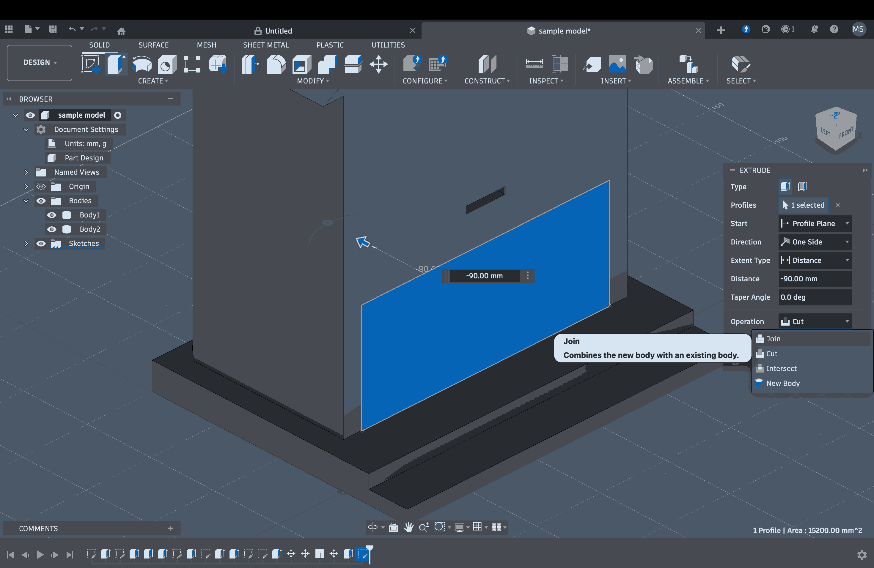
Once that was done, I decided to import an SVG file of a logo I had made in Inkscape and use it as an extruded emblem on the façade. I opened the SVG file of the dollar sign, extruded it, and then positioned it on the face.
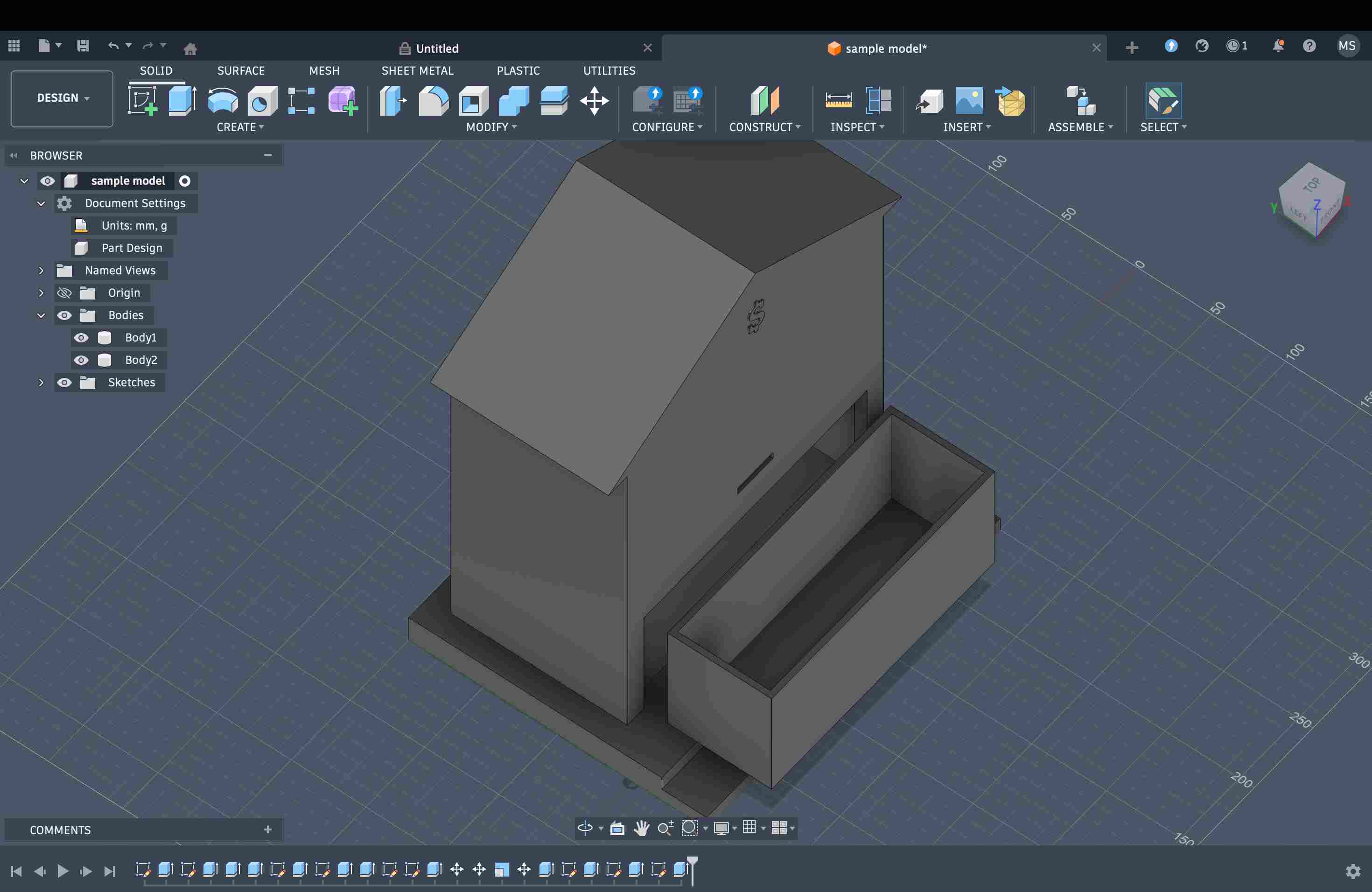
Later, I wanted to create a cut-out at the bottom front to insert a transparent tray for collecting coins. To do this, I first marked the division up to where I needed the cut and then used extrusion to create the cut-out. After that, I created another rectangular box with an open lid, matching the dimensions of the cut-out, and made it slide into the opening.
Applying Material and Rendering
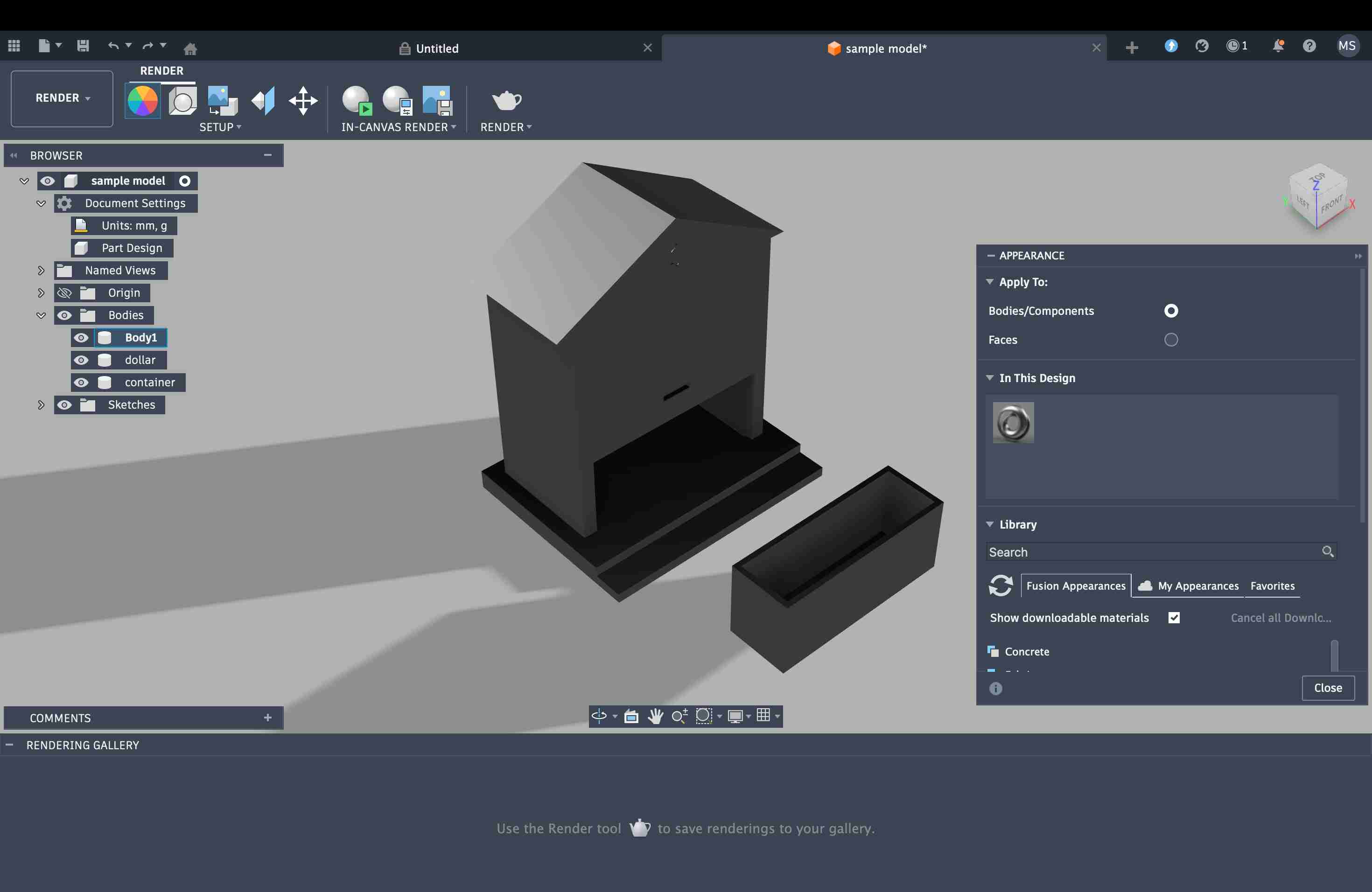
To apply materials, I switched to Render mode and selected Appearance. In this mode, materials can be applied and previewed, and the environment can also be changed. For example, I tried using soft light. I applied glass material to the transparent tray and a wood finish to the rest of the model, while keeping the dollar sign in a metallic copper finish.
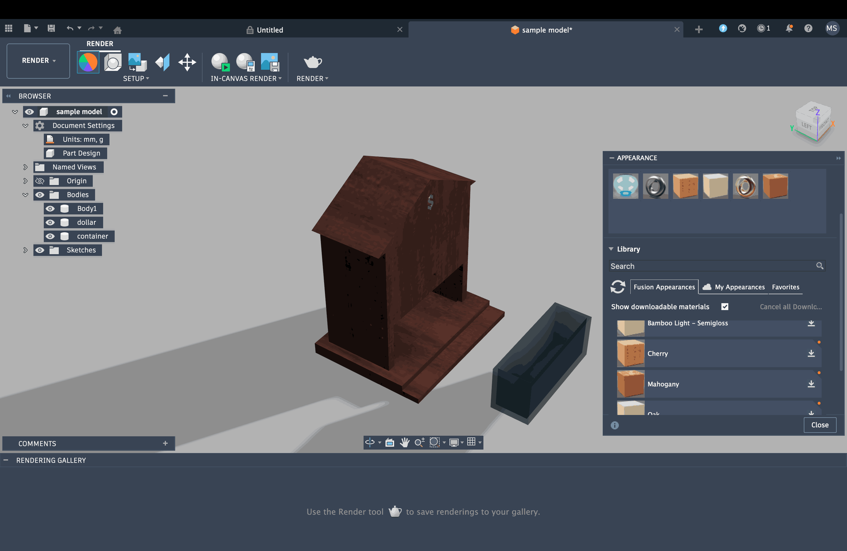
Once I hit render, the system allowed me to take snapshots and save them as rendered images. Overall, I barely managed to finish this model, but I can clearly see the potential of the software. I know I need to put in much more time and practice to truly use Fusion to my advantage.
Origami Simulator Experience
I had tried this a few years ago during an internship, and I've been folding for over 8 years now. Therefore it was easy to draft a simple V fold pattern on AutoCAD and test it online on OrigamiSimulator
.
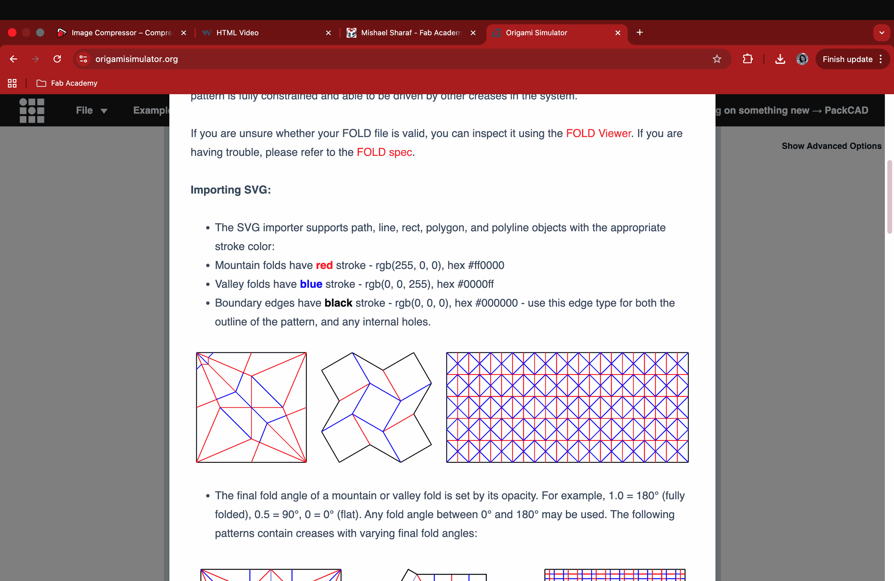
First, a simple V fold pattern was drawn and then i tried mirroring it on the other end and created a diamond pattern somewhere near the midline. After the pattern was completed, I assigned red colour for mountain folds and blue colour for valley folds according to the instructions provided on the Origami Simulator website.
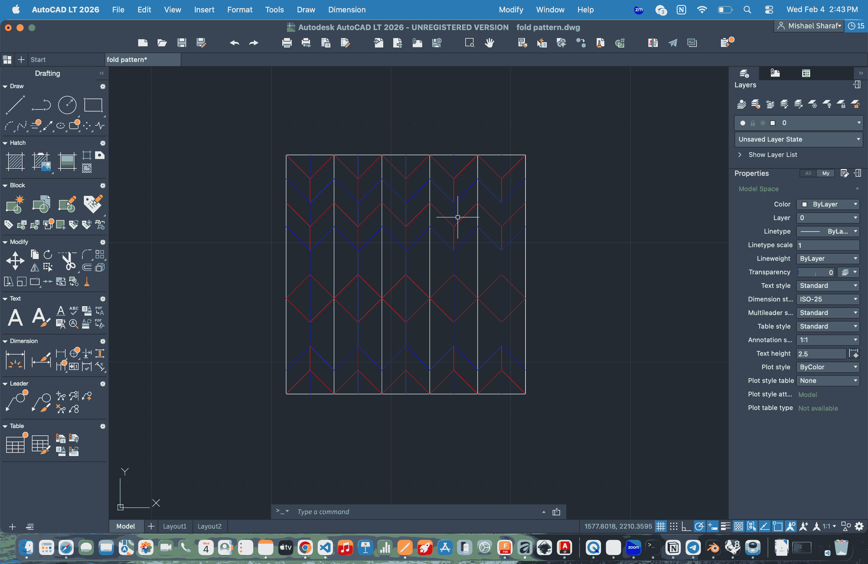
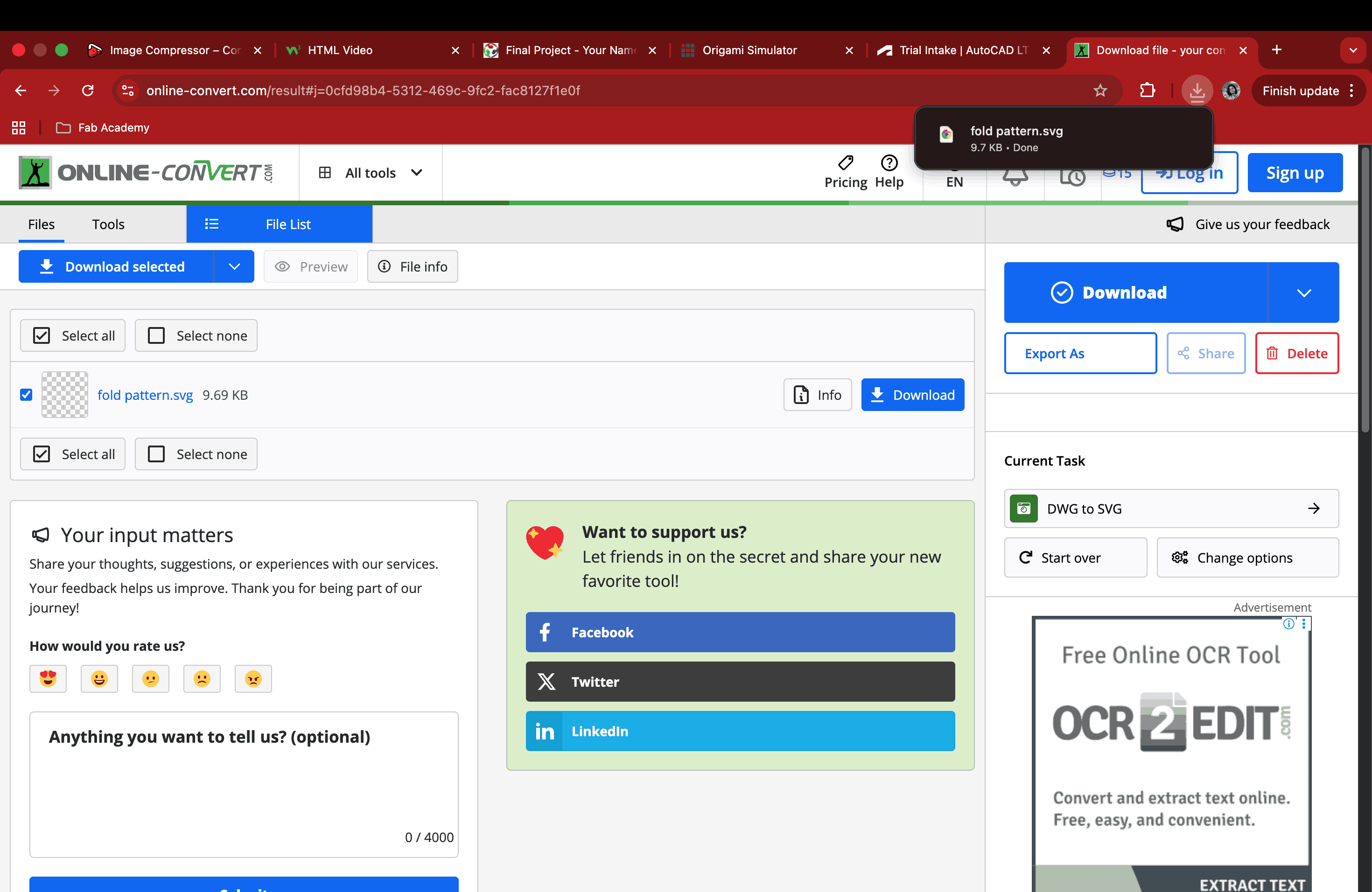
Since I was using a trial version of AutoCAD, it didn't have the option to save in svg format. So, I saved it in dwg format and used an Online Converter to convert dwg to svg.
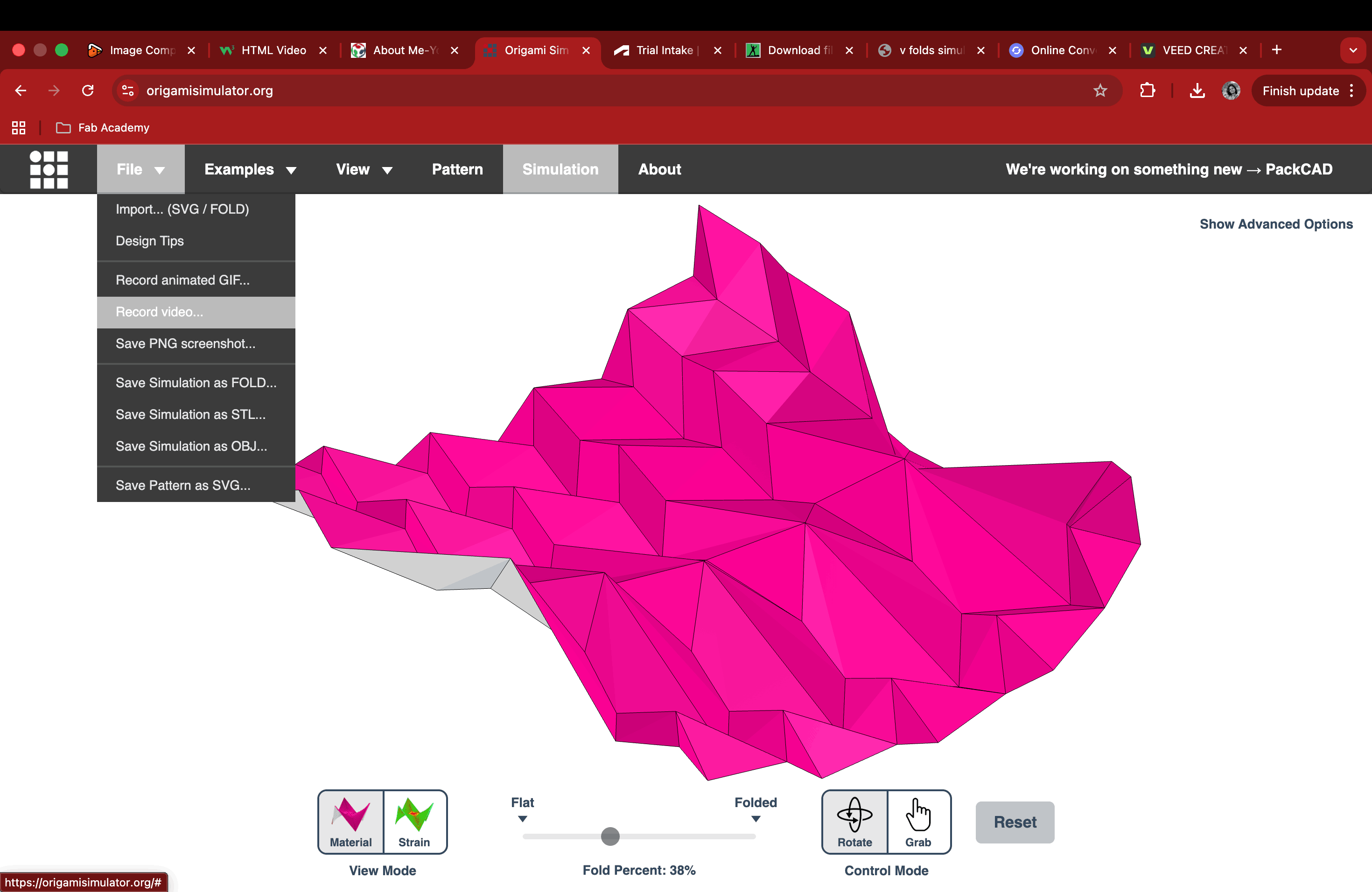
Then I finally uploaded my svg fold pattern on the Origami Simulator platform and it showed the folded version with a fold percent bar at the bottom to simulate the degree of folds.
Overall Analysis
This week’s exploration of 2D and 3D software helped me better understand how different tools support different stages of the design process. While I initially intended to work entirely in Fusion 360, the learning curve made it difficult for me to work efficiently within a limited timeframe. This pushed me to reflect more on workflow than on software choice, and I realized that using SketchUp allowed me to translate my ideas into form much faster at this stage.
Working in SketchUp felt more intuitive, especially given my background in architecture. Thinking in terms of volumes, walls, and structural elements came naturally to me. The flexibility of SketchUp’s styles also helped me move between 3D modeling and 2D representation, demonstrating how a single model can function both as a design tool and as a visual communication tool.
The shift into 2D software using Inkscape added another layer to this workflow. By converting raster screenshots from SketchUp into vector graphics through bitmap tracing, I was able to better understand the strengths and limitations of raster and vector formats. This process made it clear how 2D tools can be used not only for presentation, but also for refining and repurposing elements created in 3D.
I also had a hard time understanding Blender, as it is very different from the 3D software I have used so far, such as 3ds Max, SketchUp, and Rhino. Blender does not rely on technical dimensioning, which confused me because I am used to working precisely within set dimensions. Additionally, the interface felt overwhelming and difficult to navigate at first.
On the other hand, Fusion 360 began to make more sense once I started learning it step by step. Although it is different from the tools I have used before, it shares certain similarities with other CAD software, which made parts of it feel familiar. This gave me confidence that, with practice, I will be able to become more comfortable with it and achieve better results in the long term.
Overall, this week reinforced the idea that no single tool excels at everything. Instead, combining 3D and 2D software allowed me to move fluidly between concept development, modeling, and graphic refinement. The experience also highlighted areas where I want to improve, particularly in learning Fusion 360, while giving me confidence in building a workflow that plays to my current strengths and gradually expands my skill set.
In terms of 2D software, although I could only use the trial version of AutoCAD, it felt like home because I had used it extensively during my college days. It was also very easy to assign colors to lines in AutoCAD, something I could not figure out in Inkscape or Fusion. Since this step was absolutely necessary for the origami simulation and would not work without color coding, I decided to download the trial version. Simulating the fold always feels like magic to me. I am usually a hands-on person, and I would normally sit, draw, and crease every single fold by hand to understand what works and what does not. Doing it this way, digitally, truly feels like magic.
Image and Video Compression
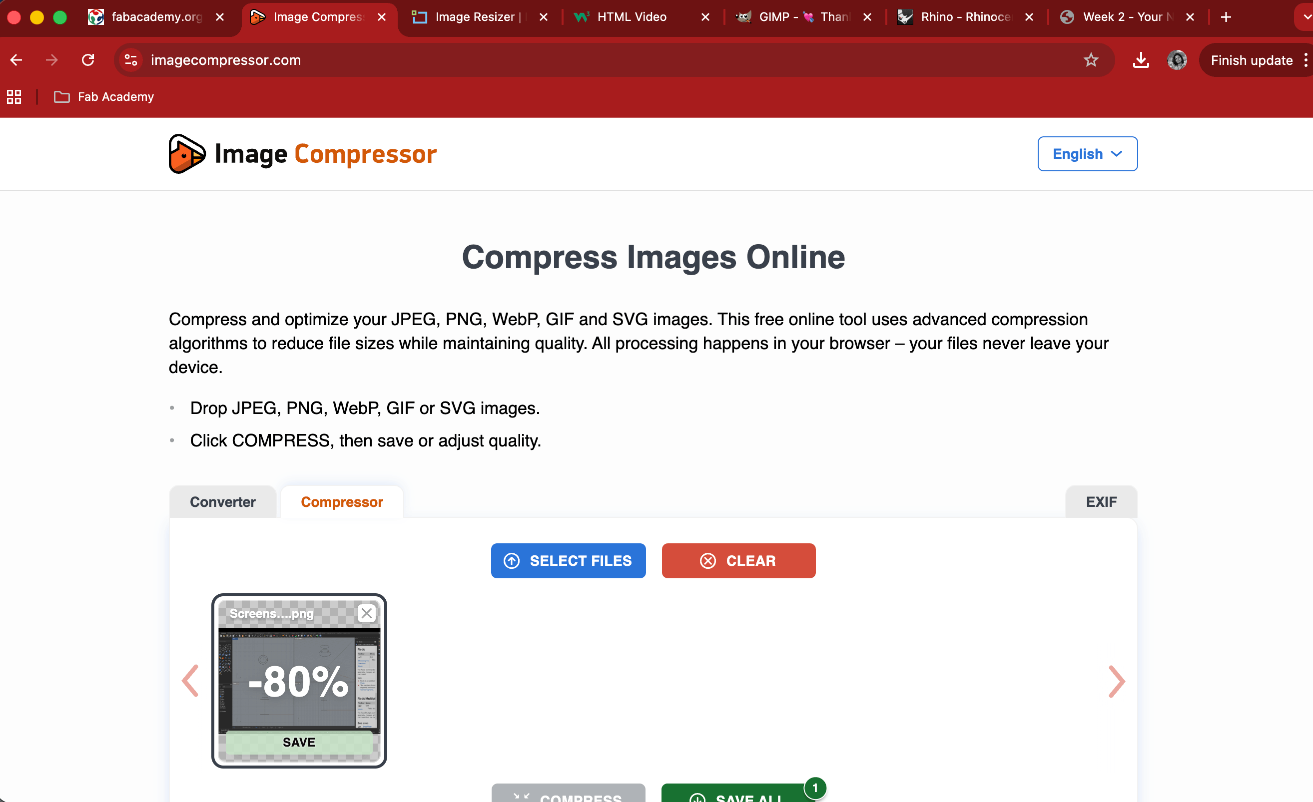
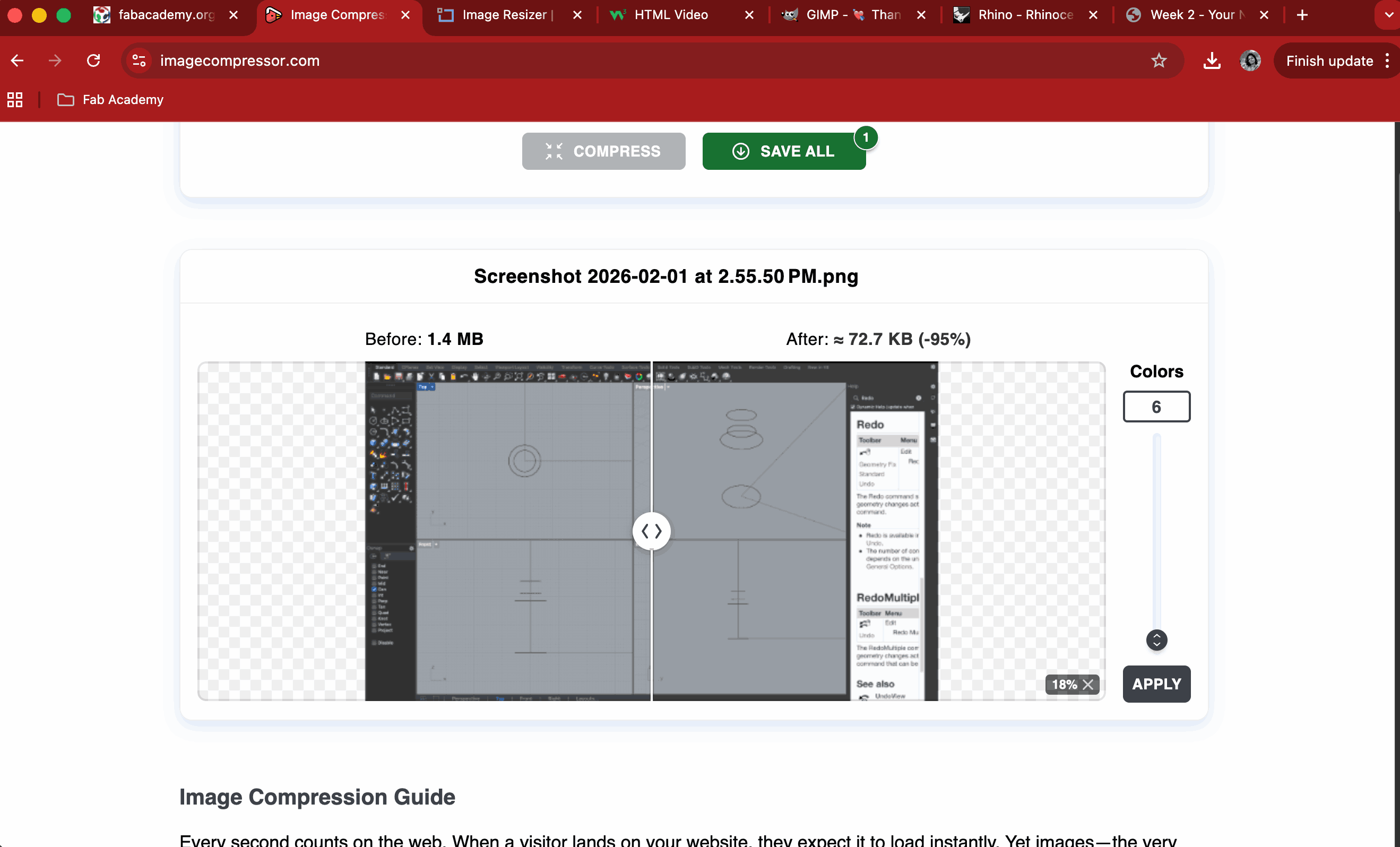
I used a free online tool called Image Compressor that uses advanced compression algorithms to reduce file sizes while maintaining quality.
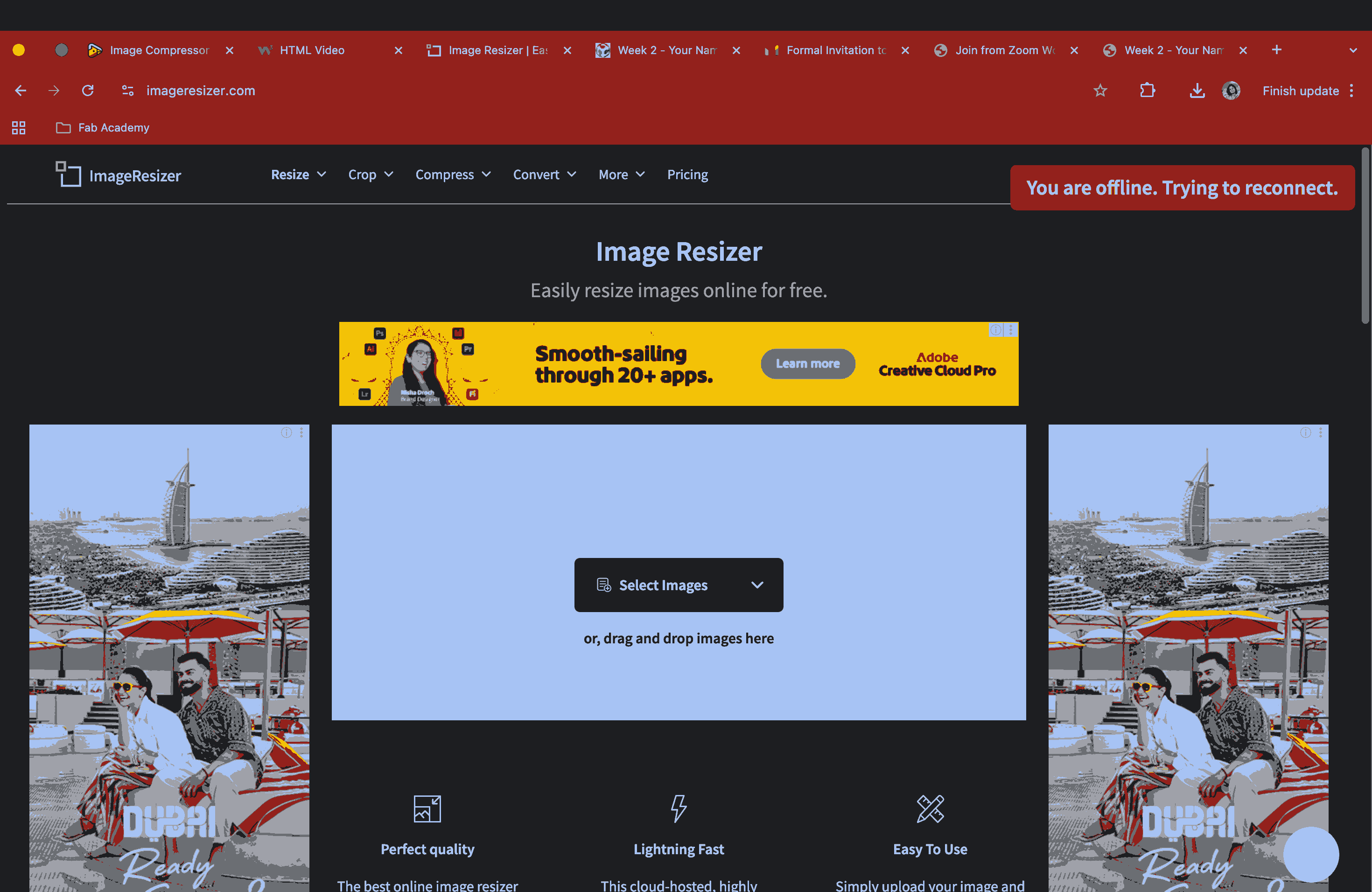
I also tried another online tool called ImageResizer. But it only allows a few free trials and then goes back to payment mode.
For Video compression, I used VEED, an online tool.
Possible Design Model for Final Project
At this stage, I explored a conceptual directions for the final smart banking companion: one inspired by a traditional piggy bank, where I experimented with modelling a pig in Blender.