11. Networking and Communication
- Group assignment
- send a message between two projects
- Individual assignment
- design, build, and connect wired or wireless node(s) with network or bus addresses and local input &/or output device(s)
Individual Assignment
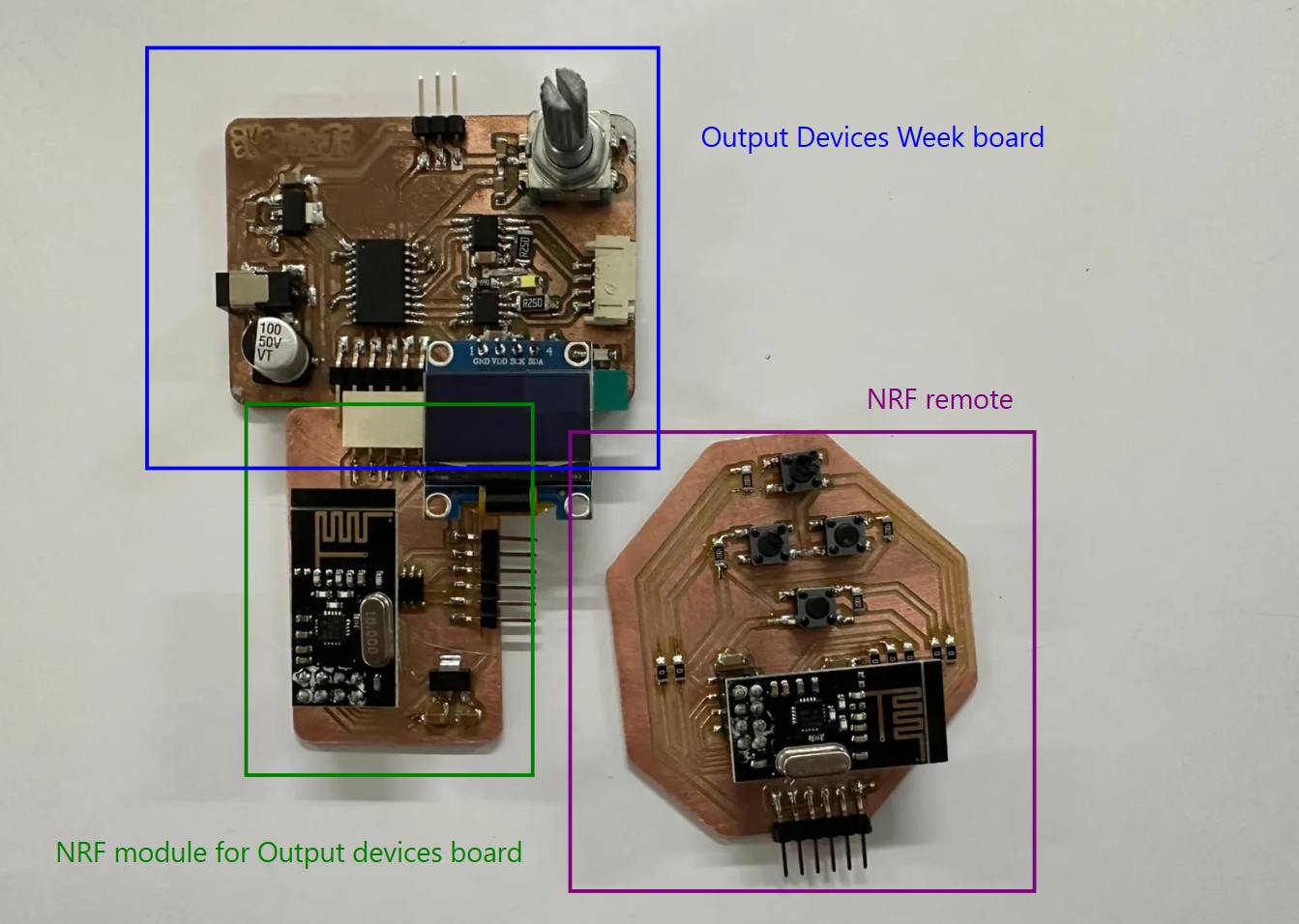
Output Week Board
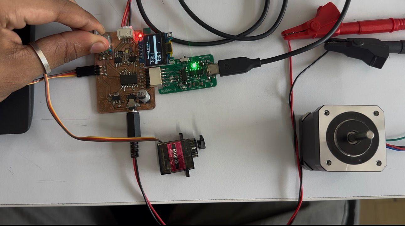
This is the Output Week board. It has a display that shows five track options connected to a servo motor and a stepper motor.
Communication Week Plan
Many of the goals I set during Output Devices Week could not be completed, so I carried those objectives forward into Communication Week.
The goals of this week are as follows:
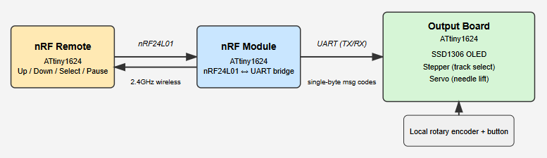
My initial plan was to redesign the Output Week board to accommodate an additional nRF module that would receive instructions from an nRF-based remote. However, I decided against redesigning the existing board. Instead, I designed a separate nRF module using another ATtiny1624, which communicates with the main output board using RX/TX serial lines.
After completing that, I designed the nRF remote module. The remote allows the user to select which track to play and pause playback simply by lifting the needle. The remote therefore includes:
- Up track
- Down track
- Select
- Pause
Block Diagram
nRF24L01
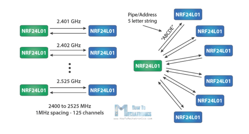
The nRF24L01 operates in the 2.4 GHz ISM band and supports data rates from 250 kbps up to 2 Mbps. Under open-space conditions and lower data rates, communication ranges can reach approximately 100 meters.
The module supports 125 RF channels, allowing multiple wireless systems to operate simultaneously within the same area. Each channel supports up to six logical addresses, enabling communication with multiple devices at once.
Communication with microcontrollers such as Arduino or ATtiny devices is performed using the SPI protocol.
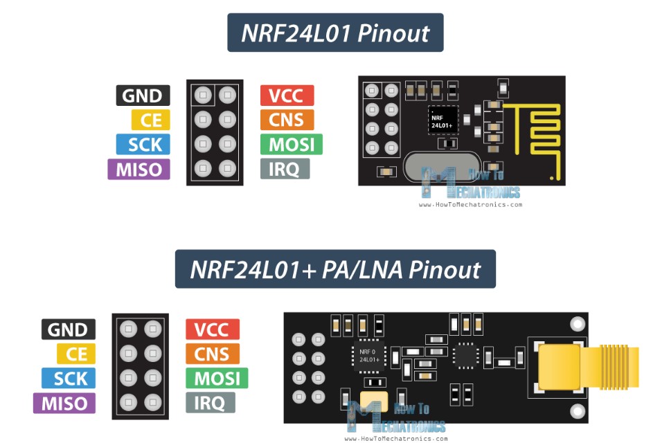
Pinout Configuration
The nRF24L01 module has eight pins:
GND
Ground connection.
VCC
Power supply input (1.9 V – 3.6 V only). Connecting
directly to 5 V will damage the module.
CE (Chip Enable)
Active HIGH pin used to switch between transmit (TX) and receive (RX) modes.
CSN (Chip Select Not)
Active LOW pin used to enable SPI communication.
SCK (Serial Clock)
SPI clock signal generated by the microcontroller.
MOSI (Master Out Slave In)
SPI data input from the microcontroller.
MISO (Master In Slave Out)
SPI data output from the module.
IRQ (Interrupt)
Active LOW interrupt output used to notify transmission or reception events.
How It Works
SPI Communication
The microcontroller operates as the SPI master while the nRF24L01 acts as the slave device. Radio configuration and payload transfer are handled through SPI commands.
Addressing
Each module uses a unique 5-byte address. Receivers listen only for matching addresses, allowing multiple devices to coexist within the same wireless network.
Operation Modes
- Standby / Idle Mode — Low power waiting state.
- TX Mode — Transmits packets from the transmit buffer.
- RX Mode — Continuously listens for incoming packets.
Auto-Acknowledgment
After successful reception, the module can automatically send an acknowledgment packet. If no acknowledgment is received, the transmitter automatically retries transmission, improving reliability without additional firmware complexity.
The operating voltage range of the nRF24L01 is 1.9 V to 3.6 V, with 3.3 V being typical. Although most communication pins tolerate 5 V logic levels, the power pin must never be connected directly to 5 V.
Power supply noise is a common cause of unstable communication. RF circuits are sensitive to ripple and transient noise, which may cause packet loss or initialization failures. Therefore, a decoupling capacitor should always be placed close to the module’s power pins.
A Low-Dropout (LDO) regulator, such as the AMS1117-3.3, is commonly used to provide a clean 3.3 V rail from a 5 V system supply dedicated to the nRF module.
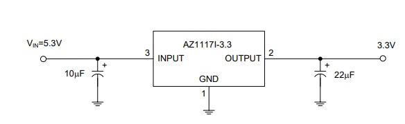
The AZ1117I linear regulator is available in fixed output voltages including 1.2 V, 1.5 V, 1.8 V, 2.5 V, 3.3 V, and 5.0 V, along with an adjustable version.
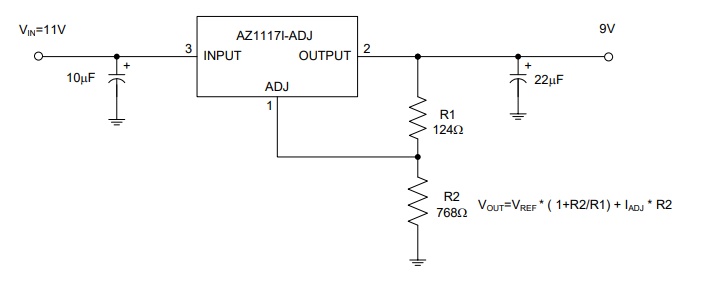
Fixed versions integrate adjustment resistors internally, simplifying design. The adjustable version allows output voltage configuration using two external resistors forming a voltage divider.
Adjustable Output Setup
https://nerdralph.blogspot.com/2014/01/nrf24l01-control-with-3-attiny85-pins.html
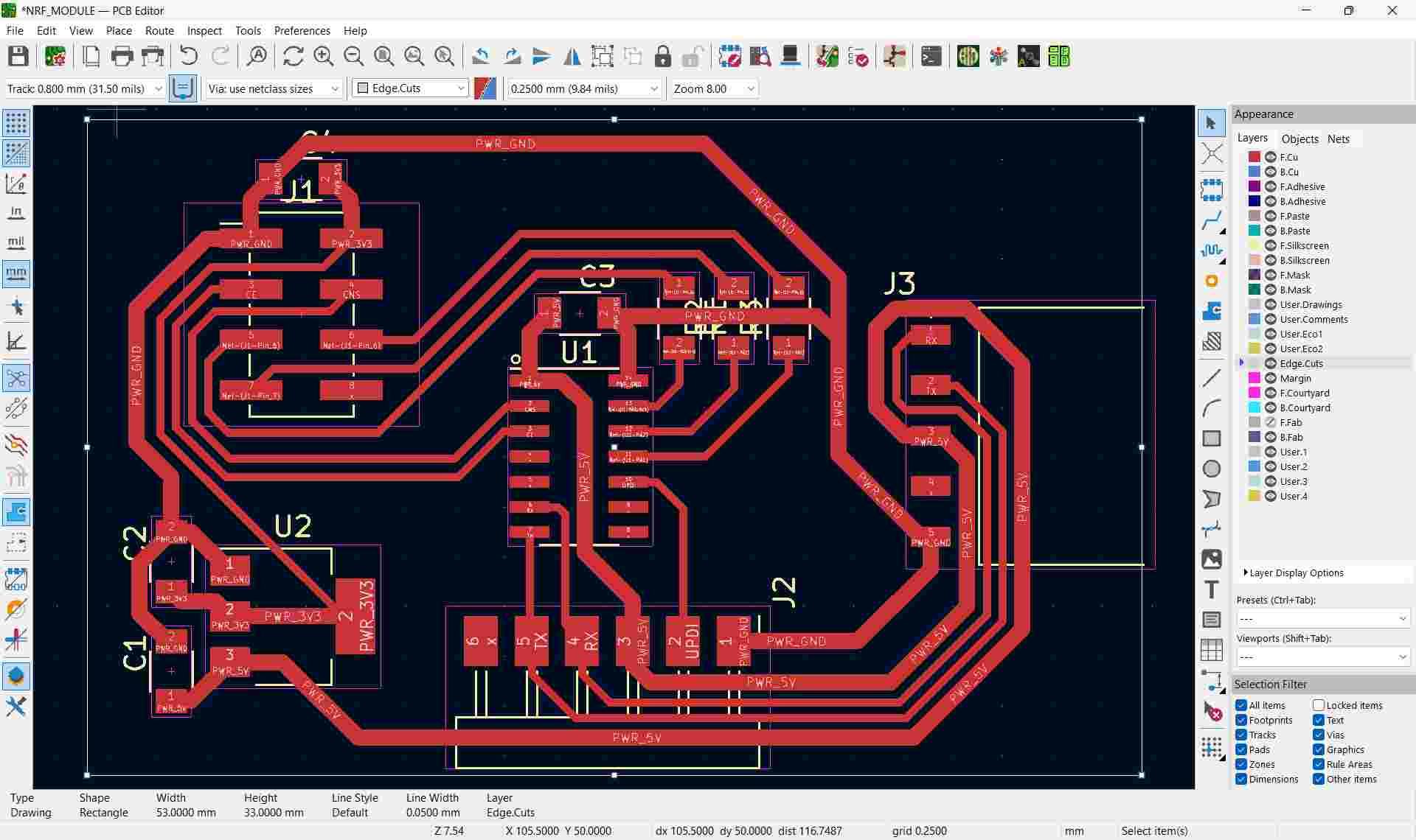
The schematic design of the nRF module for the output board
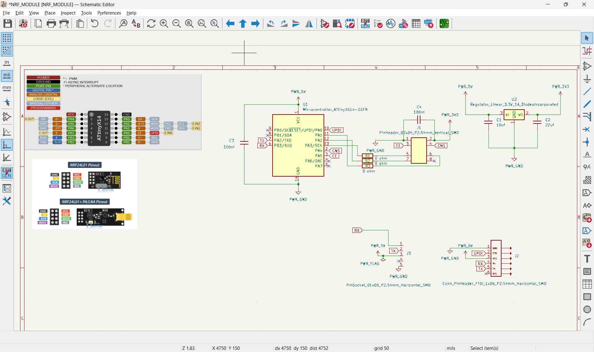

The IRQ pin was left unconnected, but it can be attached to any available microcontroller pin if interrupt functionality is required.
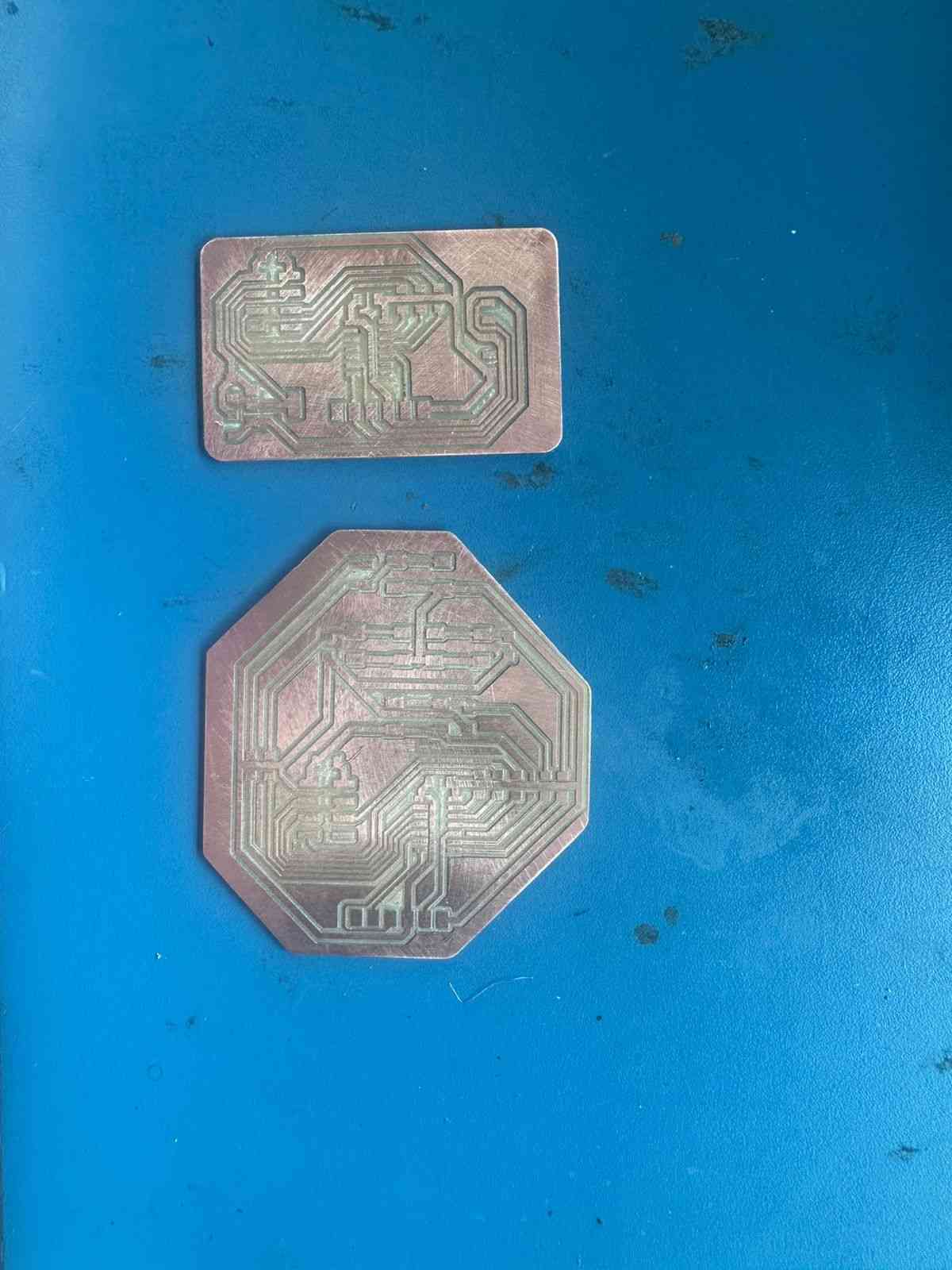
The PCB Design
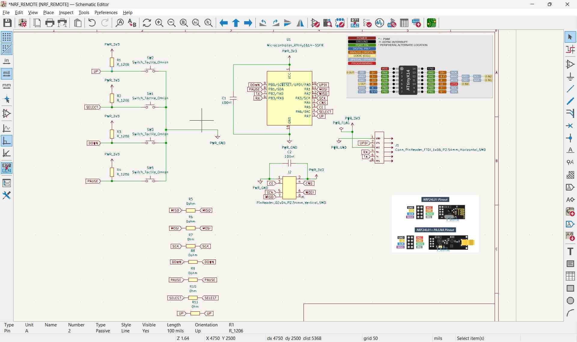
The schematic design of the nRF remote
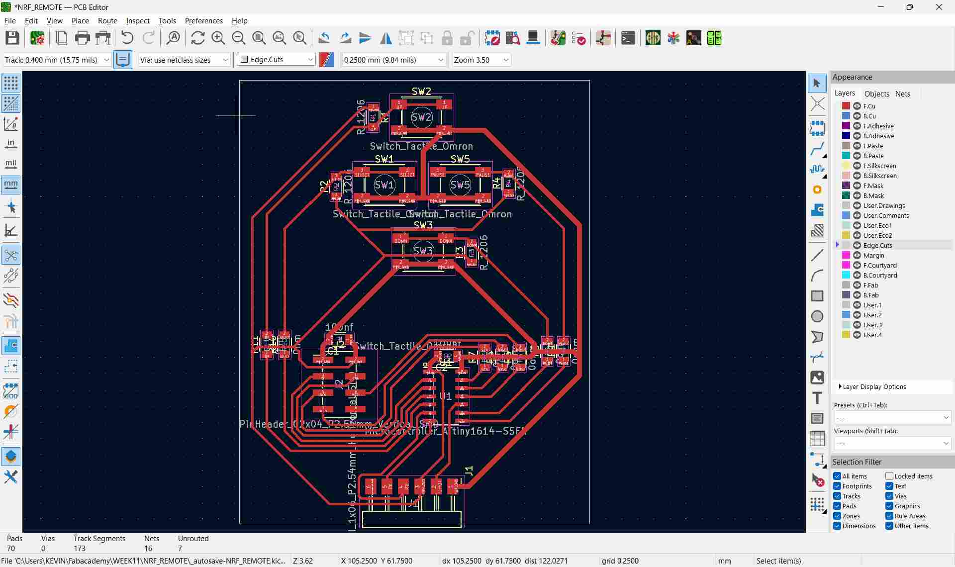
PCB design of the nRF remote
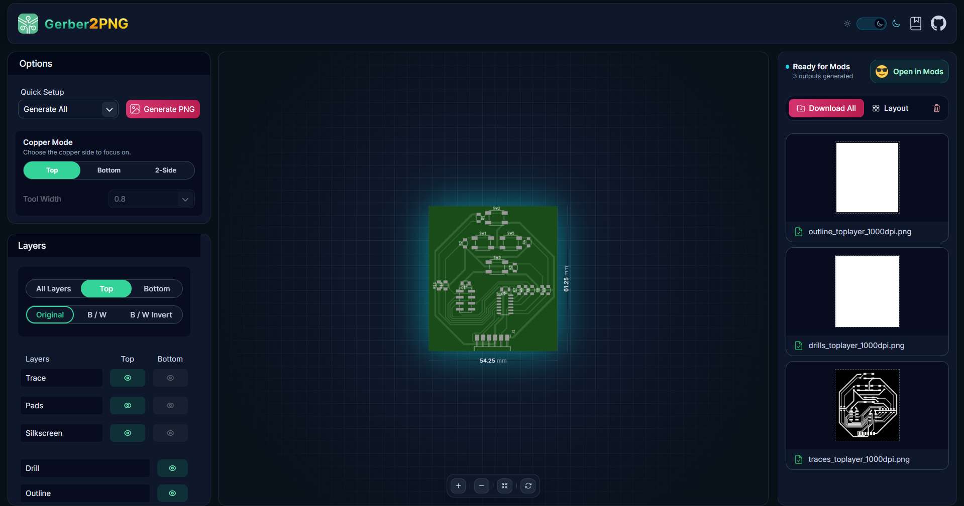
Both designs were exported using Gerber2PNG to generate Gerber files for milling. Multiple zero-ohm resistors were used to maintain a single-sided PCB layout, although a double-sided board would provide a more reliable design.
The milled board:
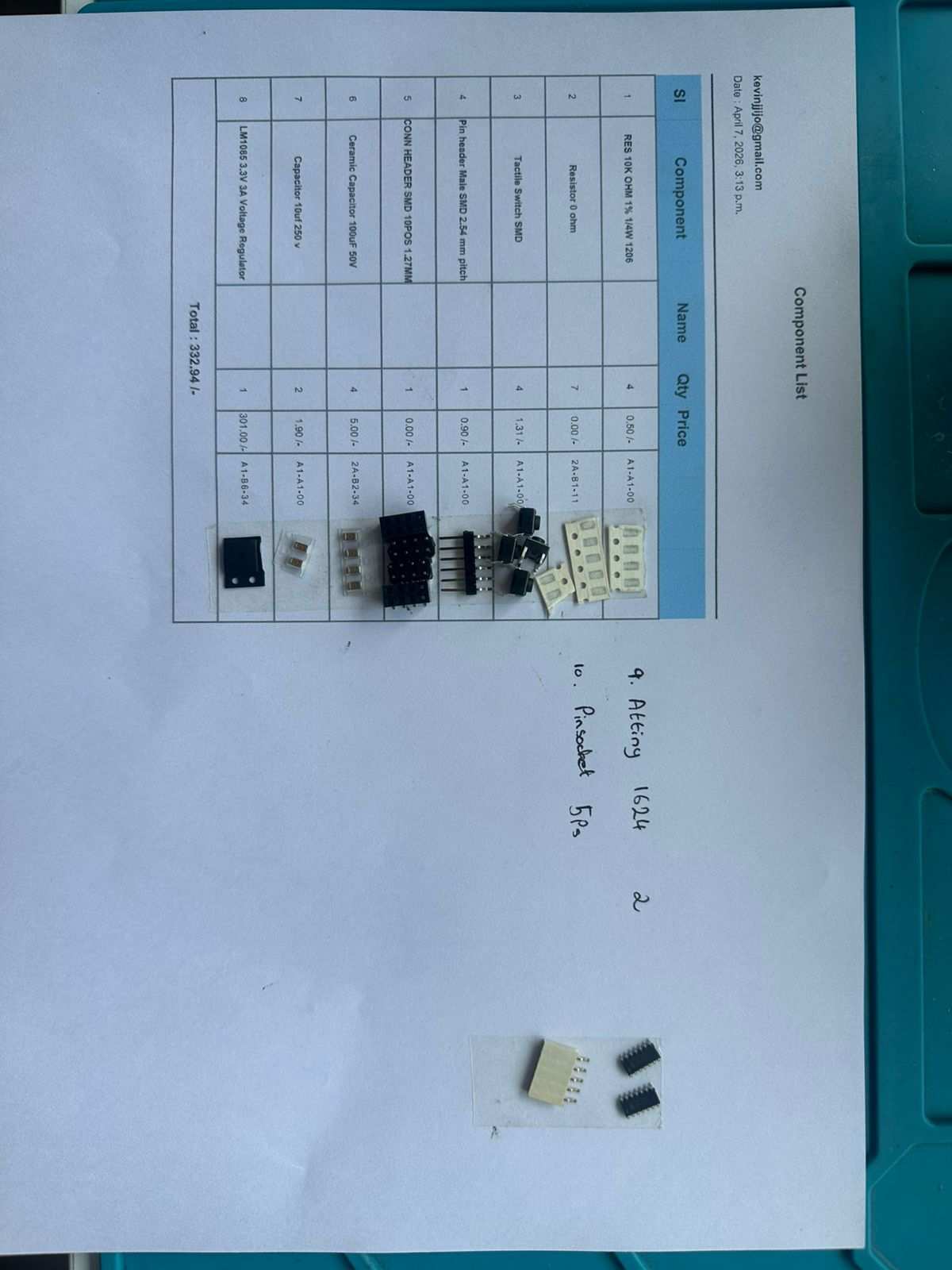
All required components:
All components soldered:
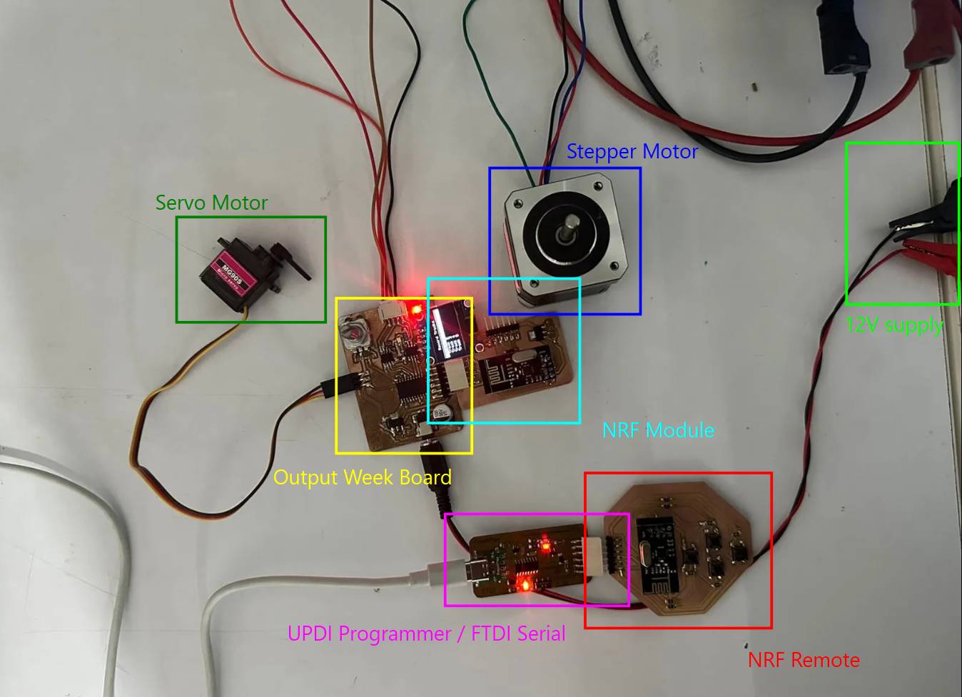
The final powered and connected circuit:
Coding the NRF Module and NRF Remote
First, I verified that both boards could communicate with the computer’s serial monitor to confirm correct operation.
Code used to test UART:
void setup() {

  Serial.begin(115200);

  delay(1000);

  Serial.println("ATtiny1624 UART Test Started");
}

void loop() {

  Serial.println("Hello from ATtiny1624");
  delay(1000);

  if (Serial.available()) {
    char c = Serial.read();

    Serial.print("Received: ");
    Serial.println(c);
  }
}
After confirming UART communication on both boards, one board was configured as a transmitter and the other as a receiver to test nRF communication. The transmitter continuously sent messages while the receiver listened and displayed received data on the serial monitor.
Transmitter Code
#include <SPI.h>
#include <RF24.h>

RF24 radio(PIN_PA3, PIN_PA7);

const byte address[6] = "00001";

void setup() {

  Serial.begin(115200);
  delay(1000);

  if (!radio.begin()) {
    Serial.println("NRF not found");
    while (1);
  }

  radio.openWritingPipe(address);
  radio.setPALevel(RF24_PA_LOW);
  radio.stopListening();

  Serial.println("Transmitter Ready");
}

void loop() {

  const char text[] = "Hello";

  bool ok = radio.write(&text, sizeof(text));

  if (ok)
    Serial.println("Sent");
  else
    Serial.println("Failed");

  delay(1000);
}
Receiver Code
#include <SPI.h>
#include <RF24.h>

RF24 radio(PIN_PA3, PIN_PA7);

const byte address[6] = "00001";

void setup() {

  Serial.begin(115200);
  delay(1000);

  if (!radio.begin()) {
    Serial.println("NRF not found");
    while (1);
  }

  radio.openReadingPipe(0, address);
  radio.setPALevel(RF24_PA_LOW);
  radio.startListening();

  Serial.println("Receiver Ready");
}

void loop() {

  if (radio.available()) {

    char text[32] = "";

    radio.read(&text, sizeof(text));

    Serial.print("Received: ");
    Serial.println(text);
  }
}
Successful testing confirmed both UART and nRF communication were working. UART is used between the output device board and the nRF module, while nRF communication links the module and remote.
Prompt used to generate these codes: Give me simple code for an NRF working on SPI to an ATtiny1624 for a transmitter and receiver. I have both; I will upload to both and read.
Final NRF Module Code
#include <SPI.h>
#include <RF24.h>

#define CE_PIN   PIN_PA5
#define CSN_PIN  PIN_PA4

RF24 radio(CE_PIN, CSN_PIN);
const byte address[6] = "00001";

#define MSG_UP      1
#define MSG_DOWN    2
#define MSG_SELECT  3
#define MSG_PAUSE   4

void setup() {
  Serial.begin(9600);

  radio.begin();
  radio.openReadingPipe(0, address);
  radio.setPALevel(RF24_PA_LOW);
  radio.startListening();
}

void loop() {
  if (radio.available()) {
    uint8_t msg;
    radio.read(&msg, sizeof(msg));

    Serial.write(msg);
  }
}
AI Prompt used: "Write firmware for a handheld remote with four pushbuttons (up, down, select, pause) on an ATtiny1624, debounced, that sends a single-byte message code over nRF24L01 each time a button is pressed."
Final NRF Remote Code
#include <SPI.h>
#include <RF24.h>

#define CE_PIN   PIN_PA5
#define CSN_PIN  PIN_PA4

RF24 radio(CE_PIN, CSN_PIN);
const byte address[6] = "00001";

#define BTN_UP      PIN_PA7
#define BTN_DOWN    PIN_PB0
#define BTN_SELECT  PIN_PA6
#define BTN_PAUSE   PIN_PB1

#define MSG_UP      1
#define MSG_DOWN    2
#define MSG_SELECT  3
#define MSG_PAUSE   4

void setup() {
  pinMode(BTN_UP,     INPUT_PULLUP);
  pinMode(BTN_DOWN,   INPUT_PULLUP);
  pinMode(BTN_SELECT, INPUT_PULLUP);
  pinMode(BTN_PAUSE,  INPUT_PULLUP);

  radio.begin();
  radio.openWritingPipe(address);
  radio.setPALevel(RF24_PA_LOW);
  radio.stopListening();
}

void loop() {
  if (digitalRead(BTN_UP) == LOW) {
    sendMessage(MSG_UP);
    waitRelease(BTN_UP);
  }
  if (digitalRead(BTN_DOWN) == LOW) {
    sendMessage(MSG_DOWN);
    waitRelease(BTN_DOWN);
  }
  if (digitalRead(BTN_SELECT) == LOW) {
    sendMessage(MSG_SELECT);
    waitRelease(BTN_SELECT);
  }
  if (digitalRead(BTN_PAUSE) == LOW) {
    sendMessage(MSG_PAUSE);
    waitRelease(BTN_PAUSE);
  }
}

void sendMessage(uint8_t msg) {
  delay(20);
  radio.write(&msg, sizeof(msg));
}

void waitRelease(uint8_t pin) {
  while (digitalRead(pin) == LOW);
  delay(20);
}
Modified Output Devices Board Code (NRF Enabled)
AI Prompt used: "Add remote-control support to my existing output board firmware. It should listen on UART for single-byte messages (up, down, select, pause) and reuse my existing track-selection and stepper/servo movement logic, without changing how the local rotary encoder already works."
#include
#include
#include
#include

#define SCREEN_WIDTH 128
#define SCREEN_HEIGHT 64
#define OLED_RESET    -1

Adafruit_SSD1306 display(SCREEN_WIDTH, SCREEN_HEIGHT, &Wire, OLED_RESET);

// Rotary encoder & button
#define ROTARY_A    PIN_PA2
#define ROTARY_B    PIN_PA1
#define ROTARY_SW   PIN_PB4

// Stepper pins
#define IN1 PIN_PC0
#define IN2 PIN_PC1
#define IN3 PIN_PC2
#define IN4 PIN_PC3

// Servo pin
#define SERVO_PIN   PIN_PA3

// Remote Controls

#define MSG_UP      1
#define MSG_DOWN    2
#define MSG_SELECT  3
#define MSG_PAUSE   4

bool paused = false;

Servo myServo;

int selectedTrack  = 1;
int activeTrack    = 0;   // 0 = none selected yet
int lastA          = HIGH;
int lastButton     = HIGH;
int stepDelay      = 2;

// 5 equal stepper positions across 200 steps (0 to 200)
const int trackPositions[6] = {0, 0, 50, 100, 150, 200};
int currentStepperPos = 0;

void setup() {
  pinMode(ROTARY_A,  INPUT_PULLUP);
  pinMode(ROTARY_B,  INPUT_PULLUP);
  pinMode(ROTARY_SW, INPUT_PULLUP);
  lastA = digitalRead(ROTARY_A);

  pinMode(IN1, OUTPUT);
  pinMode(IN2, OUTPUT);
  pinMode(IN3, OUTPUT);
  pinMode(IN4, OUTPUT);

  myServo.attach(SERVO_PIN);
  myServo.write(90);        // start at 90 (open/lifted position)

  Wire.begin();
  display.begin(SSD1306_SWITCHCAPVCC, 0x3C);
  updateDisplay();
}

void loop() {
  handleEncoder();
  handleButton();
  handleRemote();
}

// ── Rotary encoder ────────────────────────────────────────
void handleEncoder() {
  int a = digitalRead(ROTARY_A);
  if (a == LOW && lastA == HIGH) {
    if (digitalRead(ROTARY_B) == LOW) {
      selectedTrack++;
    } else {
      selectedTrack--;
    }
    if (selectedTrack > 5) selectedTrack = 1;
    if (selectedTrack < 1) selectedTrack = 5;
    updateDisplay();
  }
  lastA = a;
  delay(2);
}

// ── Button press ──────────────────────────────────────────
void handleButton() {
  int btn = digitalRead(ROTARY_SW);
  if (btn == LOW && lastButton == HIGH) {
    delay(20);                            // debounce
    if (digitalRead(ROTARY_SW) == LOW) {
      goToTrack(selectedTrack);
    }
  }
  lastButton = btn;
}

// REMOTE CONTROL

void handleRemote() {
  if (Serial.available()) {
    uint8_t msg = Serial.read();

    if (msg == MSG_UP) {
      selectedTrack--;
      if (selectedTrack < 1) selectedTrack = 5;
      updateDisplay();
    }
    else if (msg == MSG_DOWN) {
      selectedTrack++;
      if (selectedTrack > 5) selectedTrack = 1;
      updateDisplay();
    }
    else if (msg == MSG_SELECT) {
      goToTrack(selectedTrack);
    }
    else if (msg == MSG_PAUSE) {
      // pause/resume logic - you can expand this
      paused = !paused;
    }
  }
}

// ── Move to selected track ────────────────────────────────
void goToTrack(int track) {
  // Step 1: lift servo from 0 to 90 (only if already placed)
  if (activeTrack != 0) {
    servoMove(0, 90);
  }

  // Step 2: move stepper to new position
  int targetPos = trackPositions[track];
  if (targetPos > currentStepperPos) {
    int steps = targetPos - currentStepperPos;
    for (int i = 0; i < steps; i++) stepForward();
  } else if (targetPos < currentStepperPos) {
    int steps = currentStepperPos - targetPos;
    for (int i = 0; i < steps; i++) stepBackward();
  }
  currentStepperPos = targetPos;

  // Step 3: lower servo from 90 to 0
  servoMove(90, 0);

  activeTrack = track;
  updateDisplay();
}

// ── Servo slow sweep ──────────────────────────────────────
void servoMove(int from, int to) {
  if (from < to) {
    for (int pos = from; pos <= to; pos++) {
      myServo.write(pos);
      delay(15);
    }
  } else {
    for (int pos = from; pos >= to; pos--) {
      myServo.write(pos);
      delay(15);
    }
  }
}

// ── Stepper ───────────────────────────────────────────────
void stepForward() {
  digitalWrite(IN1, HIGH); digitalWrite(IN2, LOW);
  digitalWrite(IN3, HIGH); digitalWrite(IN4, LOW);  delay(stepDelay);
  digitalWrite(IN1, LOW);  digitalWrite(IN2, HIGH);
  digitalWrite(IN3, HIGH); digitalWrite(IN4, LOW);  delay(stepDelay);
  digitalWrite(IN1, LOW);  digitalWrite(IN2, HIGH);
  digitalWrite(IN3, LOW);  digitalWrite(IN4, HIGH); delay(stepDelay);
  digitalWrite(IN1, HIGH); digitalWrite(IN2, LOW);
  digitalWrite(IN3, LOW);  digitalWrite(IN4, HIGH); delay(stepDelay);
}

void stepBackward() {
  digitalWrite(IN1, HIGH); digitalWrite(IN2, LOW);
  digitalWrite(IN3, LOW);  digitalWrite(IN4, HIGH); delay(stepDelay);
  digitalWrite(IN1, LOW);  digitalWrite(IN2, HIGH);
  digitalWrite(IN3, LOW);  digitalWrite(IN4, HIGH); delay(stepDelay);
  digitalWrite(IN1, LOW);  digitalWrite(IN2, HIGH);
  digitalWrite(IN3, HIGH); digitalWrite(IN4, LOW);  delay(stepDelay);
  digitalWrite(IN1, HIGH); digitalWrite(IN2, LOW);
  digitalWrite(IN3, HIGH); digitalWrite(IN4, LOW);  delay(stepDelay);
}

// ── Display ───────────────────────────────────────────────
void updateDisplay() {
  display.clearDisplay();

  display.setTextSize(1);
  display.setTextColor(SSD1306_WHITE);
  display.setCursor(25, 5);
  display.println("Record Tracks");
  display.drawLine(0, 16, 127, 16, SSD1306_WHITE);

  for (int i = 1; i <= 5; i++) {
    int y = 20 + (i - 1) * 9;

    if (i == selectedTrack) {
      display.fillRect(0, y - 1, 128, 10, SSD1306_WHITE);
      display.setTextColor(SSD1306_BLACK);
    } else {
      display.setTextColor(SSD1306_WHITE);
    }

    display.setCursor(10, y);
    display.print("Track ");
    display.print(i);

    // show a marker on the active/loaded track
    if (i == activeTrack) {
      display.setTextColor(i == selectedTrack ? SSD1306_BLACK : SSD1306_WHITE);
      display.setCursor(90, y);
      display.print("<");
    }
  }

  display.display();
}
This is how the output devices are normally controlled:
Now the output board can also be controlled using the nRF remote.
Meeting the Addressing Requirement
My original communication assignment successfully demonstrated wireless communication between two boards using the nRF24L01 modules. However, both boards only acted as a transmitter or a receiver, which did not fully satisfy the requirement that each board must have a unique identity and communicate using an addressing scheme.
To meet this requirement, I updated the project so that both boards act as transceivers, meaning they can both transmit and receive data. Each board is assigned a unique address:
- Board A – Address 1
- Board B – Address 2
Whenever Board A sends a packet, it includes both its own address (sender) and the address of the board it wants to communicate with (receiver). Board B first checks whether the packet is addressed to it. If the receiver address matches its own, it processes the command and sends a response back. If the packet is addressed to a different board, it simply ignores it.
To demonstrate two-way communication, I connected two push buttons to Board A. Pressing the UP button sends a +1 command, while pressing the DOWN button sends a -1 command. Board B receives the command, updates an internal counter, and immediately sends the new counter value back to Board A. Both boards display the communication process through their Serial Monitors, including the packet number, sender, receiver, command, and returned value.
AI Prompt used: "Rewrite my two nRF boards so both act as transceivers with unique addresses instead of a fixed transmitter/receiver pair. Board A should have two buttons that send +1/-1 commands tagged with sender and receiver addresses, and Board B should check the address, update a counter, and send the new value back to Board A. Print sender, receiver, packet ID, and value on both serial monitors."
Assigning a Unique Identity
Each board is given a unique identity using a simple address value. Board A is assigned address 1, while Board B is assigned address 2. These addresses are stored as constants and are used whenever a packet is sent or received.
// Board A
const byte TX_PIPE[6] = "NODE2";
const byte RX_PIPE[6] = "NODE1";

// Board B
const byte TX_PIPE[6] = "NODE1";
const byte RX_PIPE[6] = "NODE2";

// Board A
const uint8_t MY_ADDRESS = 1;
const uint8_t BOARD_B = 2;

// Board B
const uint8_t MY_ADDRESS = 2;
const uint8_t BOARD_A = 1;
Adding Sender and Receiver Information
Every packet contains both the sender and receiver addresses along with a packet ID and command. This allows the receiving board to identify where the message came from and whether it is the intended destination.
struct Packet {
    uint8_t sender;
    uint8_t receiver;
    uint16_t packetID;
    int8_t command;
};
Board A Addresses the Packet
Before transmitting, Board A fills in the sender and receiver fields. In this example, Board A sends commands to Board B by setting the sender to its own address and the receiver to Board B's address.
txPacket.sender = MY_ADDRESS;
txPacket.receiver = BOARD_B;
txPacket.packetID = packetNumber++;
txPacket.command = cmd;
Board B Verifies the Address
After receiving a packet, Board B checks the receiver field. If the packet is not addressed to Board B, it ignores the message. This ensures that only the intended board responds, which satisfies the addressing requirement.
if (rxPacket.receiver != MY_ADDRESS) {
    Serial.println("Packet ignored (wrong destination)");
    return;
}
Replying to the Correct Board
After processing the command, Board B sends a response back. The sender and receiver addresses are swapped so the reply is directed specifically to Board A.
txReply.sender = MY_ADDRESS;
txReply.receiver = BOARD_A;
txReply.packetID = rxPacket.packetID;
txReply.counter = counter;
Verifying the Reply
When Board A receives the response, it checks that the reply is addressed to itself before using the returned value. This prevents Board A from processing packets intended for another device.
if (rxPacket.receiver != MY_ADDRESS) {
    Serial.println("Wrong destination");
    return;
}
Result
With this implementation, each board has a unique identity and every packet contains both sender and receiver addresses. Board A only communicates with Board B, while Board B only responds to packets addressed to it. This demonstrates an addressing scheme rather than simple point-to-point communication and satisfies the networking assignment requirement.
Code for Board A
#include <SPI.h>
#include <RF24.h>

// Pin definitions for the nRF24 module (SPI CE/CSN control lines)
#define CE_PIN  PIN_PA5
#define CSN_PIN PIN_PA4

// Pin definitions for the two push buttons used to send UP/DOWN commands
#define BTN_UP   PIN_PA7
#define BTN_DOWN PIN_PB0

// Create the radio object using the CE/CSN pins above
RF24 radio(CE_PIN, CSN_PIN);

// nRF24 pipe addresses - Board A writes to NODE2, listens on NODE1
// (Board B is configured with these swapped so both boards can talk)
const byte TX_PIPE[6] = "NODE2";
const byte RX_PIPE[6] = "NODE1";

// Logical network addresses used inside the packet itself
// (separate from the physical radio pipe addresses above)
const uint8_t MY_ADDRESS = 1;
const uint8_t BOARD_B = 2;

// Packet structure sent FROM Board A TO Board B
struct Packet {
  uint8_t sender;       // who sent this packet
  uint8_t receiver;     // who it's meant for
  uint16_t packetID;    // incrementing ID, used to match replies to requests
  int8_t command;       // +1 = increment, -1 = decrement
};

// Reply structure sent back FROM Board B TO Board A
struct Reply {
  uint8_t sender;
  uint8_t receiver;
  uint16_t packetID;    // echoes the packetID it's replying to
  int counter;          // current counter value on Board B
};

Packet txPacket;   // packet we build and send
Reply rxPacket;    // reply we receive back

uint16_t packetNumber = 0;  // running packet counter, increments with each send

// Button state tracking for edge detection (so a single press = one command)
bool lastUp = HIGH;
bool lastDown = HIGH;

// Builds a packet, sends it to Board B, and waits for an ACK/reply
void sendCommand(int8_t cmd)
{
  // Fill in the packet fields
  txPacket.sender = MY_ADDRESS;
  txPacket.receiver = BOARD_B;
  txPacket.packetID = packetNumber++;
  txPacket.command = cmd;

  Serial.println("----------------------------");
  Serial.print("Sending Packet #");
  Serial.println(txPacket.packetID);

  Serial.print("Command : ");
  if (cmd > 0)
    Serial.println("UP (+1)");
  else
    Serial.println("DOWN (-1)");

  // Must stop listening before writing (radio can't TX and RX at once)
  radio.stopListening();

  bool success = radio.write(&txPacket, sizeof(txPacket));

  // Go back to listening mode to catch the reply
  radio.startListening();

  if (!success)
  {
    Serial.println("Send Failed");
    return;
  }

  // Wait up to 500ms for a reply from Board B
  unsigned long start = millis();

  while (millis() - start < 500)
  {
    if (radio.available())
    {
      radio.read(&rxPacket, sizeof(rxPacket));

      // Make sure this reply is actually addressed to us
      if (rxPacket.receiver != MY_ADDRESS)
      {
        Serial.println("Wrong destination");
        return;
      }

      Serial.println("ACK RECEIVED");

      Serial.print("Packet : ");
      Serial.println(rxPacket.packetID);

      Serial.print("Remote Counter = ");
      Serial.println(rxPacket.counter);

      return;
    }
  }

  // No reply arrived within the timeout window
  Serial.println("Timeout waiting for reply");
}

void setup()
{
  // Buttons wired active-low with internal pullups
  pinMode(BTN_UP, INPUT_PULLUP);
  pinMode(BTN_DOWN, INPUT_PULLUP);

  Serial.begin(115200);

  while (!Serial);  // wait for serial monitor to connect

  Serial.println();
  Serial.println("===== BOARD A =====");
  Serial.println("Address = 1");

  // Initialize the radio - halt if it's not detected
  if (!radio.begin())
  {
    Serial.println("NRF FAILED");
    while (1);
  }

  // Radio configuration - must match Board B exactly
  radio.setPALevel(RF24_PA_LOW);
  radio.setDataRate(RF24_250KBPS);
  radio.setRetries(5,15);

  // Set up TX/RX pipes
  radio.openWritingPipe(TX_PIPE);
  radio.openReadingPipe(1, RX_PIPE);

  radio.startListening();

  Serial.println("Ready");
}

void loop()
{
  bool up = digitalRead(BTN_UP);
  bool down = digitalRead(BTN_DOWN);

  // Detect falling edge (button just pressed) to avoid repeat triggers
  if (lastUp == HIGH && up == LOW)
  {
    sendCommand(+1);
    delay(150);  // simple debounce
  }

  if (lastDown == HIGH && down == LOW)
  {
    sendCommand(-1);
    delay(150);  // simple debounce
  }

  lastUp = up;
  lastDown = down;
}
Code for Board B
#include <SPI.h>
#include <RF24.h>

// Same physical pins as Board A (each board has its own nRF24 module)
#define CE_PIN  PIN_PA5
#define CSN_PIN PIN_PA4

RF24 radio(CE_PIN, CSN_PIN);

// nRF24 pipes - opposite of Board A so TX/RX line up correctly
const byte TX_PIPE[6] = "NODE1";
const byte RX_PIPE[6] = "NODE2";

// Logical network addresses
const uint8_t MY_ADDRESS = 2;
const uint8_t BOARD_A = 1;

// Must match Board A's Packet struct exactly (same byte layout)
struct Packet {
  uint8_t sender;
  uint8_t receiver;
  uint16_t packetID;
  int8_t command;
};

// Must match Board A's Reply struct exactly
struct Reply {
  uint8_t sender;
  uint8_t receiver;
  uint16_t packetID;
  int counter;
};

Packet rxPacket;   // incoming command packet
Reply txReply;     // outgoing reply packet

int counter = 0;   // running total, adjusted by incoming UP/DOWN commands

void setup() {

  Serial.begin(115200);

  while (!Serial);

  Serial.println();
  Serial.println("===== BOARD B =====");
  Serial.println("Address = 2");
  Serial.println("Waiting for packets...");

  if (!radio.begin()) {
    Serial.println("NRF FAILED");
    while (1);
  }

  // Must match Board A's radio settings
  radio.setPALevel(RF24_PA_LOW);
  radio.setDataRate(RF24_250KBPS);
  radio.setRetries(5, 15);

  radio.openWritingPipe(TX_PIPE);
  radio.openReadingPipe(1, RX_PIPE);

  radio.startListening();
}

void loop() {

  // Do nothing until a packet actually arrives
  if (!radio.available())
    return;

  radio.read(&rxPacket, sizeof(rxPacket));

  Serial.println("----------------------------");

  Serial.print("Packet #");
  Serial.println(rxPacket.packetID);

  Serial.print("From Address : ");
  Serial.println(rxPacket.sender);

  Serial.print("To Address   : ");
  Serial.println(rxPacket.receiver);

  // Address filtering - only process packets meant for this board
  if (rxPacket.receiver != MY_ADDRESS) {

    Serial.println("Packet ignored (wrong destination)");
    return;
  }

  // Update local counter based on the received command
  if (rxPacket.command > 0) {

    counter++;
    Serial.println("Command : UP");

  } else {

    counter--;
    Serial.println("Command : DOWN");
  }

  Serial.print("Counter = ");
  Serial.println(counter);

  // Build the reply, echoing back the same packetID so Board A
  // can match this reply to the request it sent
  txReply.sender = MY_ADDRESS;
  txReply.receiver = BOARD_A;
  txReply.packetID = rxPacket.packetID;
  txReply.counter = counter;

  // Switch to TX mode to send the reply, then back to listening
  radio.stopListening();

  bool ok = radio.write(&txReply, sizeof(txReply));

  radio.startListening();

  if (ok)
    Serial.println("Reply Sent");
  else
    Serial.println("Reply Failed");
}
This implementation demonstrates bidirectional wireless communication while also satisfying the addressing requirement, as every packet contains both a sender and receiver identity and each board only responds to messages specifically addressed to it.
Group Assignment
The objective of the group assignment was to demonstrate communication between two independently developed projects. Rather than simply connecting two microcontrollers, the goal was to establish a reliable communication method by agreeing on a common protocol and ensuring both systems could correctly exchange and interpret data.
Reflection
This assignment highlighted that networking extends beyond direct communication between two microcontrollers. It can also be used to connect different hardware platforms, communication protocols, and independently developed projects into a single system.
For our demonstration, we integrated Nadec's custom PCB with Mishael's two-board audio system. The communication chain combined both TCP over Wi-Fi and ESP-NOW, allowing information to travel between multiple devices using different networking technologies.
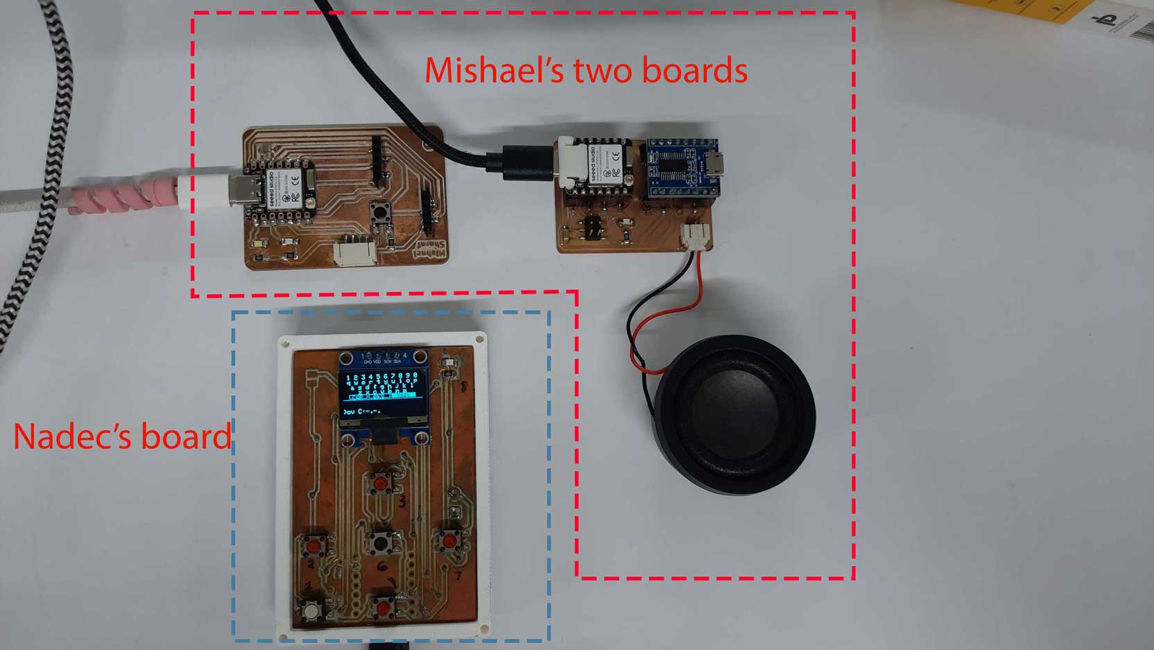
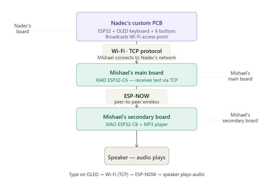
The communication flow began with user input on an OLED interface, which was sent over a TCP connection to an ESP32-C6. The ESP32-C6 then forwarded the command using ESP-NOW to Mishael's secondary board, which received the message and triggered the corresponding audio playback. Each board handled a specific task while communicating seamlessly with the others.
This exercise reinforced the importance of selecting appropriate communication protocols and designing systems that can interoperate with independently developed hardware. Building modular devices that communicate reliably is a key principle in embedded systems design and provides a strong foundation for developing larger, scalable projects.
Results can be found on the group assignment page of our lab.