10. Output Devices
- Group assignment
- Measure the power consumption of an output device.
- Document your work on the group work page and reflect on your individual page what you learned
- Individual assignment
- Add an output device to a microcontroller board you’ve designed and program it to do something.
Group Assignment
As part of the group assignment, we measured the power consumption of a servo motor and NeoPixel LEDs using a bench power supply. Instead of relying solely on datasheet specifications, we measured the actual current drawn by each device under operation and calculated the corresponding power consumption.
The electrical power consumed by a device can be calculated using:
Power (W) = Voltage (V) × Current (A)
NeoPixel Power Consumption
For the NeoPixel measurement, the power supply was set to 5 V, and the current drawn by the LEDs was measured using the bench power supply.
- Supply Voltage = 5 V
- Measured Current = 0.0337 A
- Calculated Power = 5 × 0.0337 = 0.1685 W
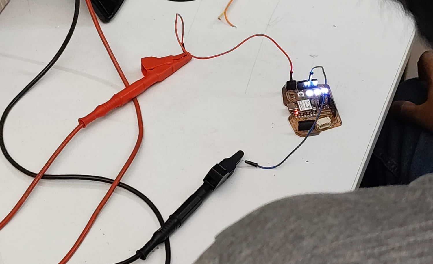
NeoPixel power consumption measurement setup.
Stepper Motor Power Consumption
The same procedure was repeated for the stepper motor by measuring the current while the motor was operating.
- Supply Voltage = 5 V
- Measured Current = 0.011 A
- Calculated Power = 5 × 0.011 = 0.055 W
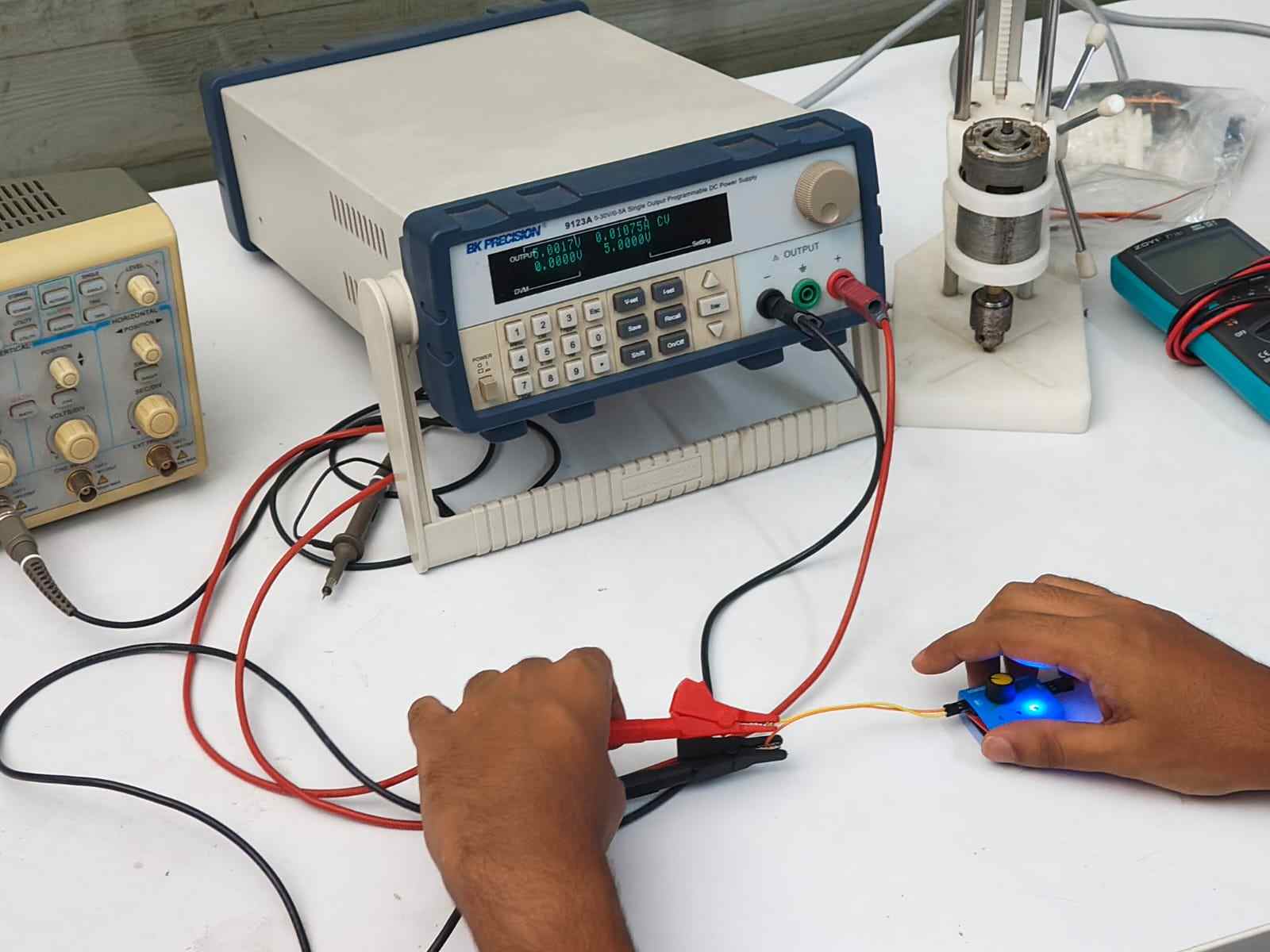
Stepper motor power consumption measurement setup.
This exercise demonstrated how practical current measurements can be used to determine the real power consumption of electronic devices, providing a more accurate understanding of system power requirements than relying solely on theoretical values.
Results can be found on the group assignment page of our lab.
Individual Assignment
This week focused on exploring different output devices and integrating them into a single embedded system. I tested an OLED display, servo motor, stepper motor, and their respective motor drivers before combining them into one working project. The final integrated system allows a rotary encoder to select a track on the OLED display while controlling both the servo and stepper motor together.
Output Devices Used
OLED Display
The SSD1306 is a single-chip CMOS OLED/PLED driver with an integrated controller designed for organic or polymer light emitting diode dot-matrix displays. The display used here is a 128 × 64 pixel module consisting of 128 segments and 64 commons, designed for common cathode type OLED panels.
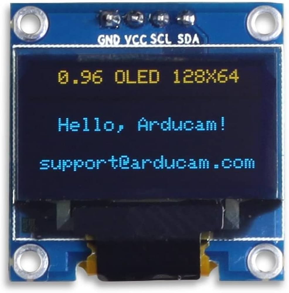
Image Credits: Original Source
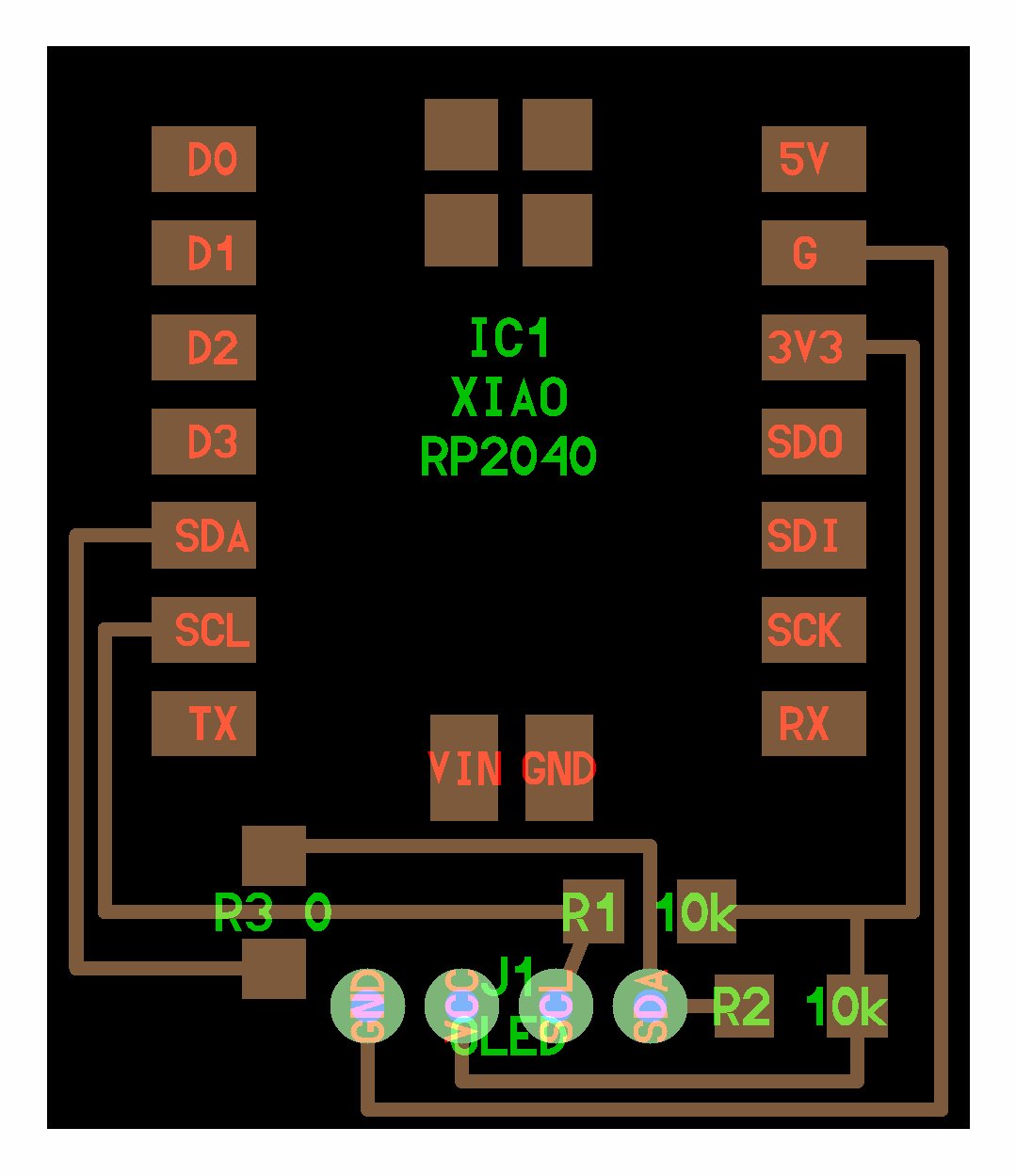
Image Credits: Original Source
This OLED display communicates over I2C, which keeps wiring simple while still allowing full graphical control. The plan was to use the display to show available tracks, playback status, and possibly volume or system feedback information.
Since the display is graphical rather than character based, it allows flexible UI design such as track lists, icons, animations, and system diagnostics during development.
The display used is a 128 × 64 pixel SSD1306 OLED module which communicates using the I²C communication protocol. I²C requires only two signal lines, SDA (data) and SCL (clock), making it suitable for connecting multiple devices while using very few GPIO pins.
The OLED used in this project operates at the default I²C address 0x3C, which is specified in the Arduino code when initializing the display.
Datasheet: SSD1306 Datasheet
Servo Motor
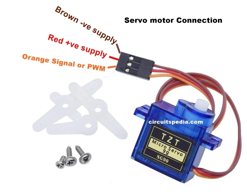
Image Credits: Original Source
Servo motors are specialized motors that include an internal feedback mechanism allowing precise control of angular position, speed, and acceleration. A typical servo contains a small DC motor, a potentiometer for position sensing, and an internal control circuit.
The motor speed is proportional to the difference between the current position and the desired position. When the error is large, the motor moves quickly; as it approaches the target angle, movement slows down. This behavior is known as proportional control.
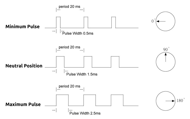
Image Credits: Original Source
A standard hobby servo motor was used to raise and lower the tonearm. Servo motors contain an internal feedback system which allows them to move accurately to a commanded angle using PWM signals generated by the microcontroller.
Servos are controlled using pulse width modulation (PWM). A control pulse is sent approximately every 20 ms, and the width of the pulse determines the angular position of the shaft.
Once commanded, the servo moves to the desired angle and actively holds that position. If an external force attempts to move it, the servo resists based on its torque rating. The position signal must continuously repeat; otherwise, the servo will stop maintaining position.
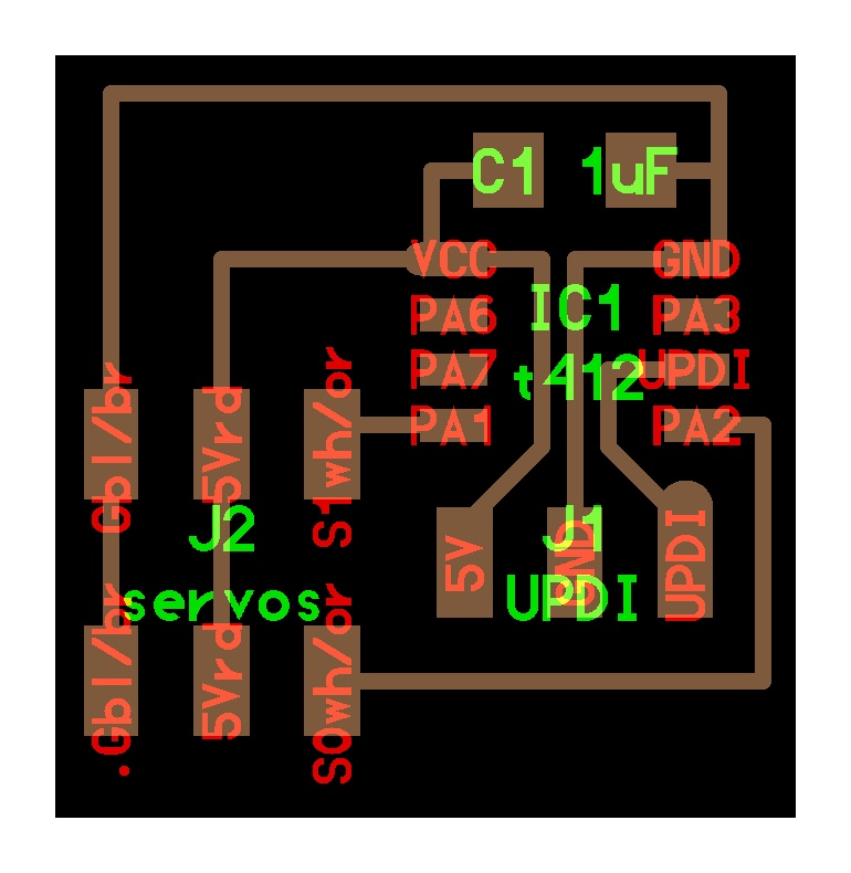
Image Credits: Original Source
In this project, the servo motor is used to lift and lower the tonearm onto the vinyl record after the correct track position has been reached.
Stepper Motor
A stepper motor is a brushless DC motor that divides a full rotation into a large number of discrete steps. This makes it ideal for applications requiring precise positioning without needing complex feedback systems.
The motor consists of two main components: the stator, which contains electromagnetic coils, and the rotor, typically made from permanent magnets or soft magnetic material.
By energizing stator coils sequentially, magnetic fields are generated that pull the rotor from one step position to the next, producing controlled rotational motion.
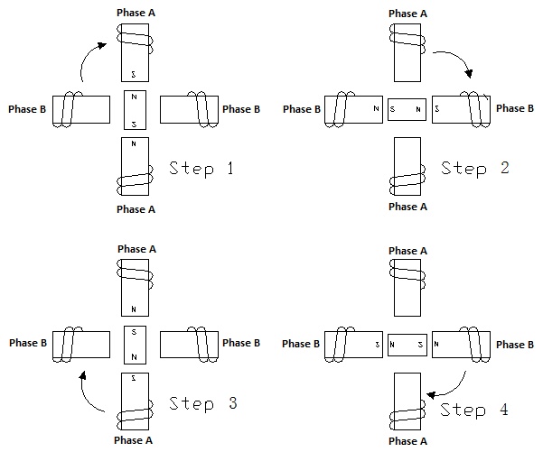
Image Credits: Original Source
The stepper motor used is a bipolar stepper motor. Bipolar steppers contain two coils and require an H-bridge motor driver to reverse current through each coil. They generally provide higher torque than unipolar stepper motors.
Comparison of common stepper motor types:
- Unipolar: Easier to drive but produces lower torque.
- Bipolar: Requires an H-bridge driver and provides higher torque.
- Hybrid: Combines permanent magnet and variable reluctance designs and is the most common precision stepper motor.
Stepper Motor Driver — DRV8428PWPR
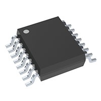
Image Credits: Original Source
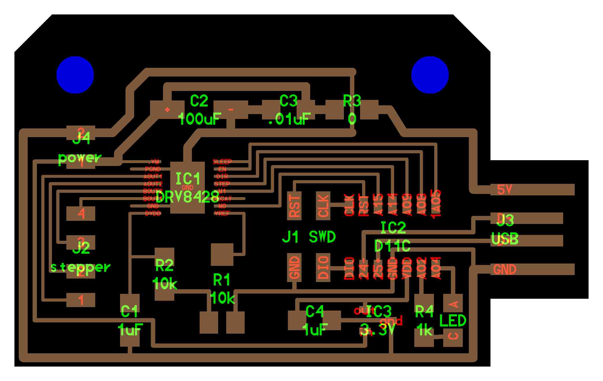
Image Credits: Original Source
The DRV8428PWPR driver is used to control the stepper motor. The driver handles coil sequencing, current regulation, and efficient switching, allowing the microcontroller to command precise step movements using simple control signals.
DRV8428PWPR Datasheet: Texas Instruments DRV8428 Datasheet
The stepper motor is responsible for moving the tonearm horizontally across the record to reach the correct groove location. Once positioned, the servo motor lowers the tonearm.
A4953 Motor Driver
The A4953 is a compact motor driver capable of controlling DC motors and stepper motors. It operates across a wide voltage range from 4V to 40V and functions as an H-Bridge driver, allowing bidirectional motor control.
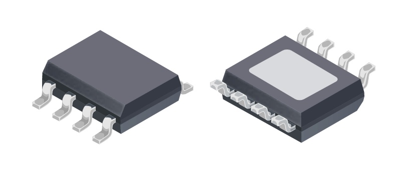
Image Credits: Original Source
A4953 Motor Driver Datasheet: Allegro A4953 Datasheet
An H-Bridge allows current to flow through the motor in either direction. By controlling two input pins (IN1 and IN2), the motor can rotate forward or backward. Applying PWM signals enables speed control.
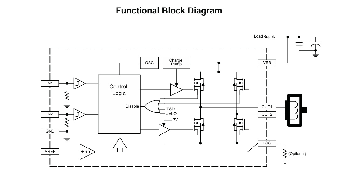
Image Credits: Original Source
If both inputs are LOW, the motor free-runs and stops gradually. If both inputs are HIGH, the motor actively brakes. Proper passive components such as capacitors and resistors are required to ensure stable operation of the driver.
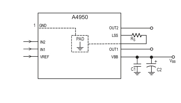
Image Credits: Original Source
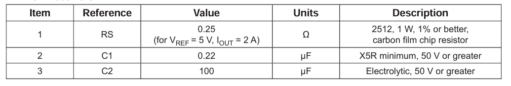
Image Credits: Original Source
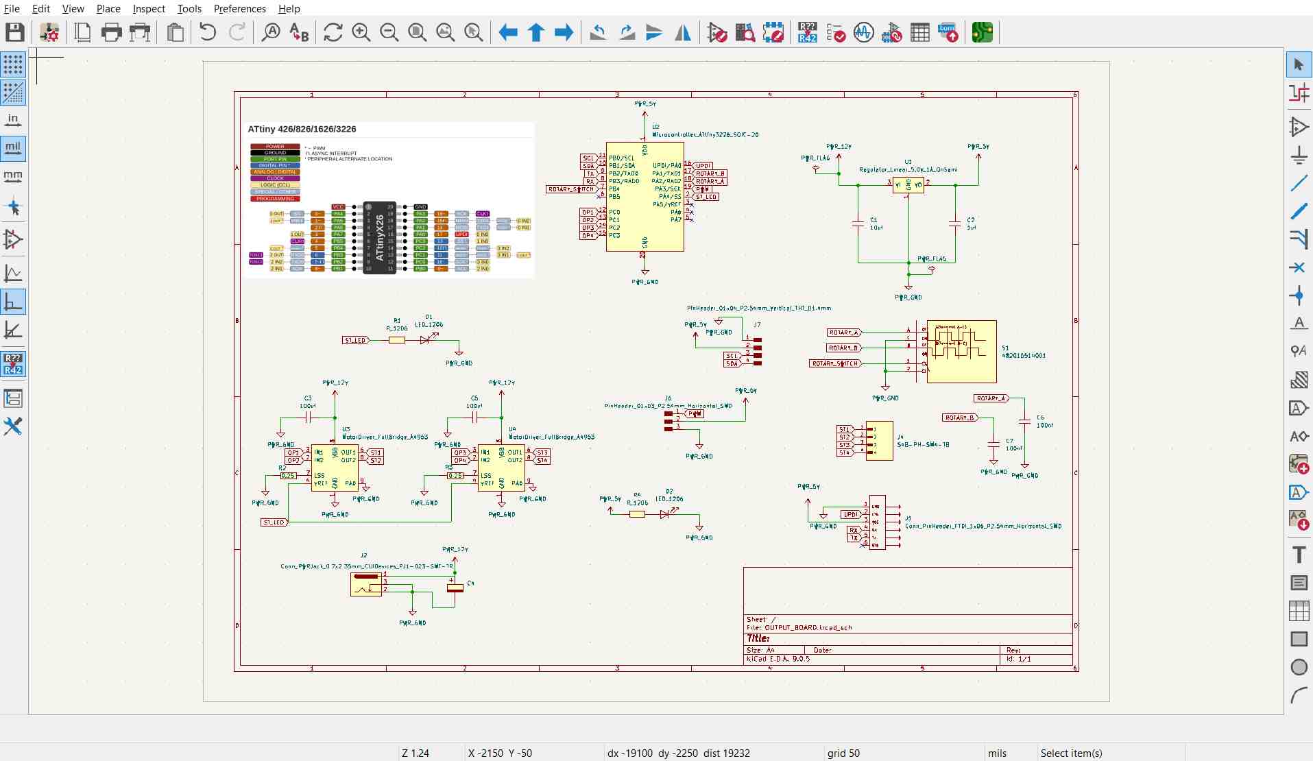
Circuit Design
The board needed to support multiple output devices including a stepper motor, servo motor, and OLED display. This required handling different voltage domains, communication interfaces, and motor control circuitry on a single PCB.
The design includes:
- Voltage regulation for multiple supply rails
- I2C interface for the OLED display
- Dual H-Bridge configuration for stepper control
- PWM output line for servo control
- Rotary encoder input for user interaction and track selection
The schematic design:
Voltage Regulation
The stepper motor operates at 12V, while the ATtiny3226 microcontroller and logic circuitry operate at 5V. An external 12V supply is therefore stepped down using a voltage regulator to safely power the logic electronics.
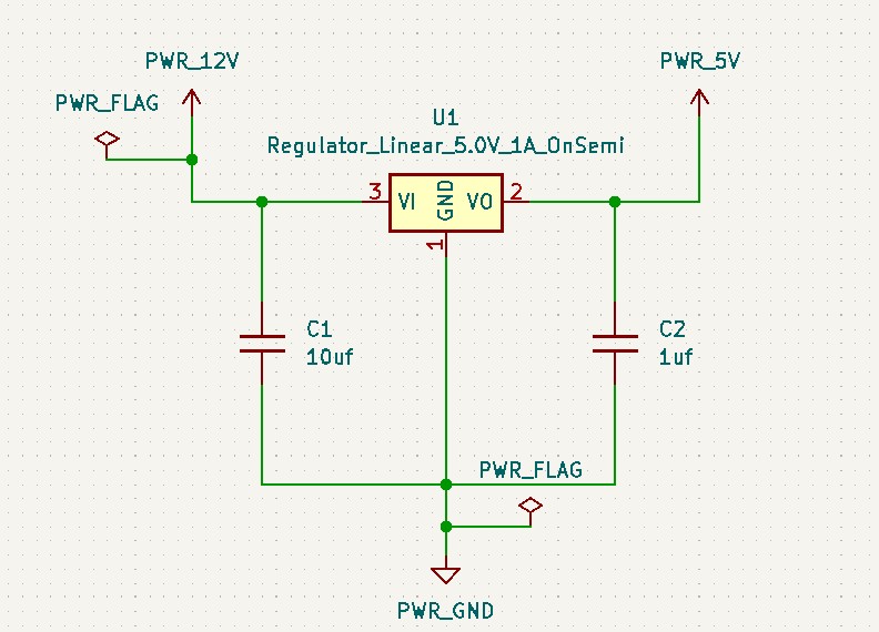
If a voltage regulator is placed far from the power source, bypass capacitors are required to filter AC noise and ripple. These capacitors stabilize the input supply and ensure clean DC power for reliable microcontroller operation.
Double H-Bridge
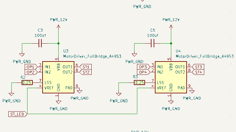
The double H-Bridge configuration allows independent control of the stepper motor windings, enabling accurate stepping motion required for tonearm positioning.
12V Connector Socket
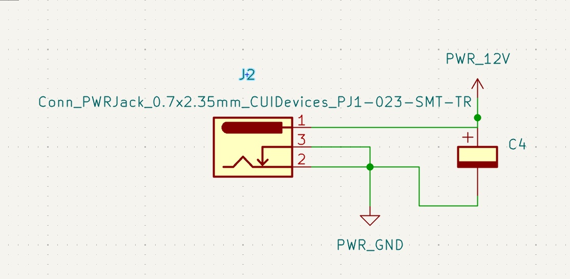
An electrolytic capacitor placed between 12V and ground acts as bulk storage and a decoupling filter. It smooths voltage fluctuations, absorbs switching noise, and supplies short bursts of current during motor load changes, preventing voltage dips.
PCB Design
The completed PCB integrates power regulation, motor drivers, display interface, and control inputs into a single board.
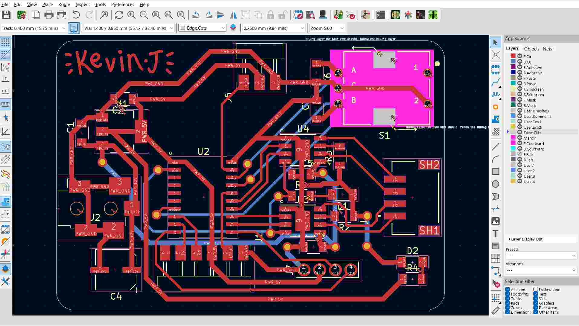
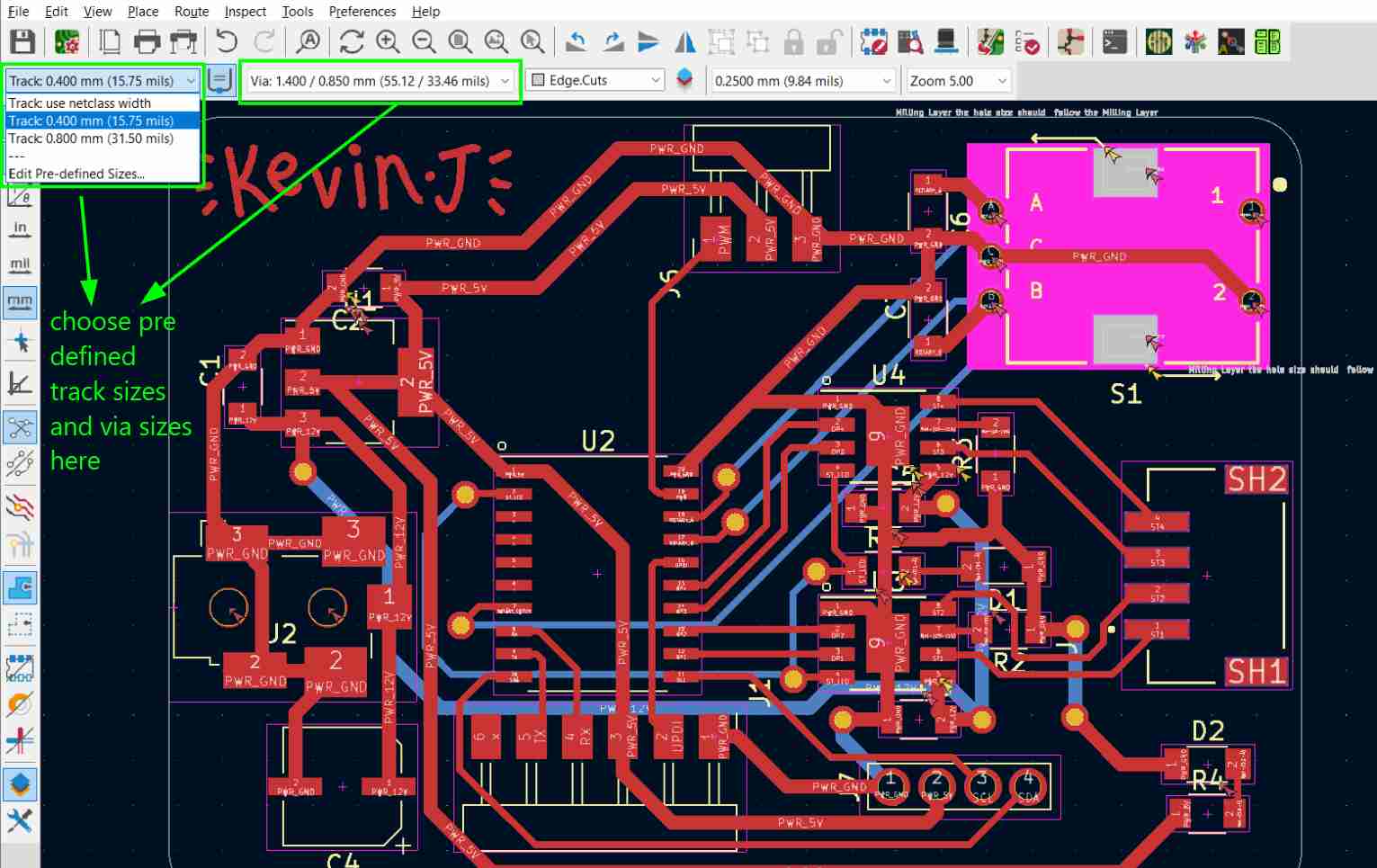
Larger track widths were used for the 12V and ground power lines. Higher voltage and motor currents require wider copper traces to reduce resistance and prevent overheating due to Joule heating.
Proper via sizes were configured in the design rules using predefined sizes.
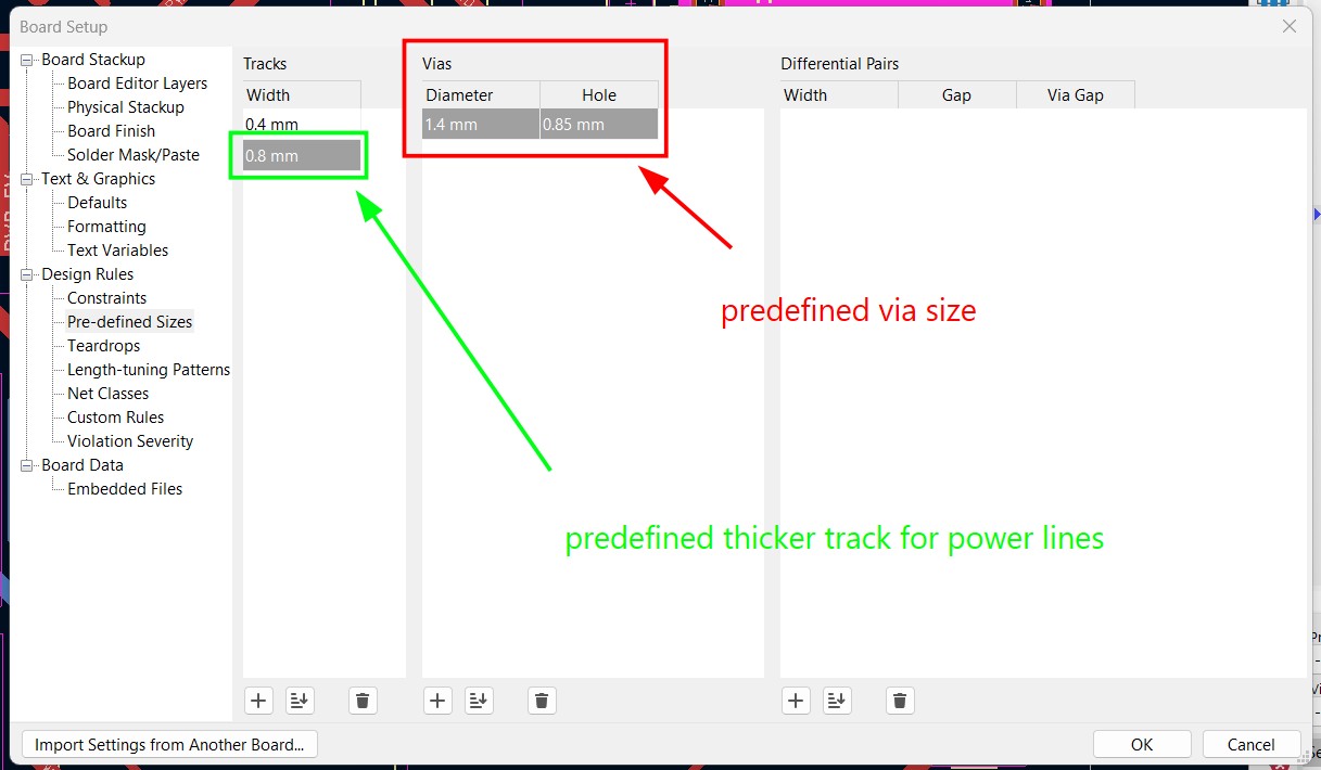
Predefined via sizes were selected rather than using custom netclasses for this design.
Milling and Soldering
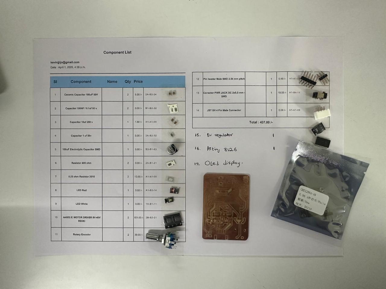
The PCB was milled and all components were assembled and soldered.
Components collected alongside the milled board:
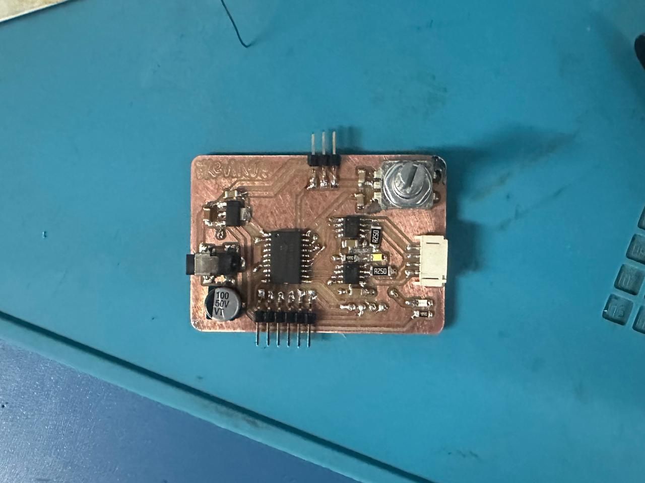
Completed soldered board:
Preparing the Output Devices
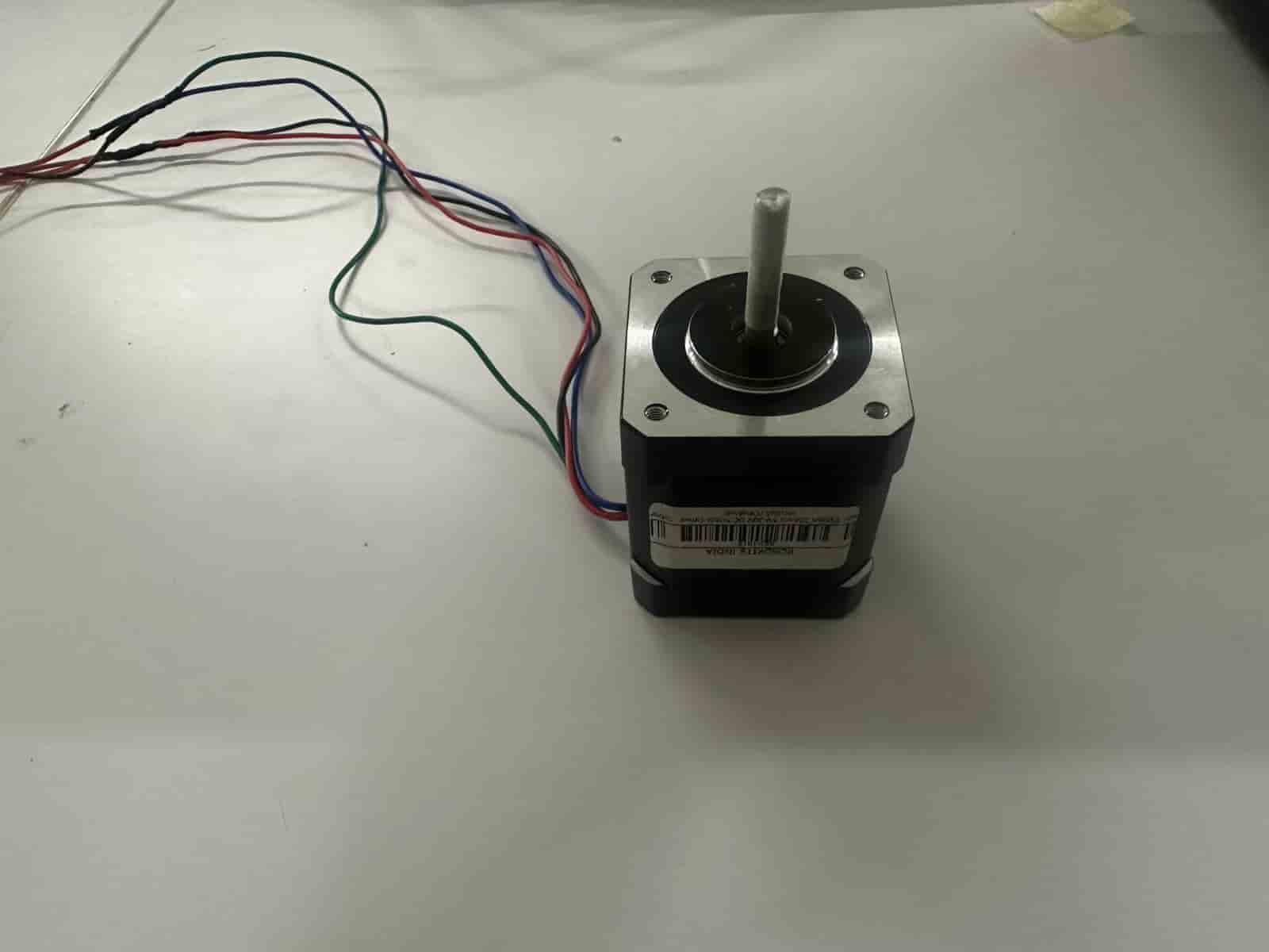
Stepper Motor
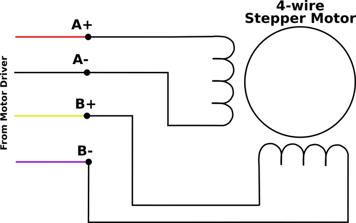
Image Credits: Original Source
The first step was preparing the stepper motor. The main requirement was to identify the two separate coil pairs (A+, A− and B+, B−). Using a multimeter, the pairs with low resistance were identified and each pair was connected to one motor driver output.
Reference video used: https://www.youtube.com/watch?v=kNyAcAHLET8
Blue and red wires, and green and blue wires showed low resistance between them, indicating the coil pairs. The measured resistance was approximately between 2–50 ohms.
Another method to verify the coil pairing is to short any two wires together and manually rotate the motor shaft. If increased resistance is felt while turning, those two wires belong to the same coil.
After identifying the coils and setting up the connector, the motor could be interfaced with the custom board.
Image Credits: Original Source
These are the servo motor connections.
All the Output Devices connected to the Output Board.
.jpg)
Powering the System
The integrated system was powered using an OWON SPE6102 programmable DC bench power supply. During testing, the supply was configured to provide a regulated 5 V DC output, which powered the complete system while allowing the output voltage and current to be monitored in real time. The bench power supply provides an adjustable output of 0–60 V and up to 10 A, making it suitable for safely testing embedded systems and motors under different operating conditions. :contentReference[oaicite:0]{index=0}
Alligator clips were used to connect the power supply to the power jack which in turn is connected to the on board soldered power jack port.
The XIAO ESP32-C6, OLED display, servo motor, and stepper motor driver were all powered from the same regulated 5 V supply. A common ground was shared between every component to ensure reliable communication and correct operation of the system.
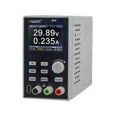
Image Credits: Original Source
.jpg)
Libraries Used
Before uploading the code, the required libraries must be installed through the Arduino IDE. Open Sketch → Include Library → Manage Libraries... to launch the Library Manager.
Search for each library by name, select the official version, and click Install. For this project I installed:
.jpg)
| Library | Purpose |
|---|---|
| Wire.h | I²C communication with the OLED display. |
| Adafruit_GFX.h | Graphics library for drawing text and shapes. |
| Adafruit_SSD1306.h | Driver library for the SSD1306 OLED display. |
| Servo.h | Controls the servo motor using PWM. |
Code for Stepper Motor
#define IN1 PIN_PC0
#define IN2 PIN_PC1
#define IN3 PIN_PC2
#define IN4 PIN_PC3

int stepDelay = 1;

void setup() {
  pinMode(IN1, OUTPUT);
  pinMode(IN2, OUTPUT);
  pinMode(IN3, OUTPUT);
  pinMode(IN4, OUTPUT);
}

void stepForward() {
  digitalWrite(IN1,HIGH); digitalWrite(IN2,LOW);
  digitalWrite(IN3,HIGH); digitalWrite(IN4,LOW);
  delay(stepDelay);

  digitalWrite(IN1,LOW); digitalWrite(IN2,HIGH);
  digitalWrite(IN3,HIGH); digitalWrite(IN4,LOW);
  delay(stepDelay);

  digitalWrite(IN1,LOW); digitalWrite(IN2,HIGH);
  digitalWrite(IN3,LOW); digitalWrite(IN4,HIGH);
  delay(stepDelay);

  digitalWrite(IN1,HIGH); digitalWrite(IN2,LOW);
  digitalWrite(IN3,LOW); digitalWrite(IN4,HIGH);
  delay(stepDelay);
}

void stepBackward() {
  digitalWrite(IN1,HIGH); digitalWrite(IN2,LOW);
  digitalWrite(IN3,LOW); digitalWrite(IN4,HIGH);
  delay(stepDelay);

  digitalWrite(IN1,LOW); digitalWrite(IN2,HIGH);
  digitalWrite(IN3,LOW); digitalWrite(IN4,HIGH);
  delay(stepDelay);

  digitalWrite(IN1,LOW); digitalWrite(IN2,HIGH);
  digitalWrite(IN3,HIGH); digitalWrite(IN4,LOW);
  delay(stepDelay);

  digitalWrite(IN1,HIGH); digitalWrite(IN2,LOW);
  digitalWrite(IN3,HIGH); digitalWrite(IN4,LOW);
  delay(stepDelay);
}

void loop() {
  for(int i=0;i<200;i++) stepForward();
  delay(1000);

  for(int i=0;i<200;i++) stepBackward();
  delay(1000);
}
Code for Servo Motor
#include <Servo.h>

Servo myServo;

void setup() {
  myServo.attach(PIN_PA3);
}

void loop() {
  myServo.write(0);
  delay(1000);
  myServo.write(90);
  delay(1000);
  myServo.write(150);
  delay(1000);
}
Code for OLED Display
#include <Wire.h>
#include <Adafruit_GFX.h>
#include <Adafruit_SSD1306.h>

#define SCREEN_WIDTH 128
#define SCREEN_HEIGHT 64
#define OLED_RESET -1

Adafruit_SSD1306 display(SCREEN_WIDTH, SCREEN_HEIGHT, &Wire, OLED_RESET);

#define ROTARY_A PIN_PA2
#define ROTARY_B PIN_PA1

int selectedTrack = 1;
int lastA = HIGH;

void setup() {
  pinMode(ROTARY_A, INPUT_PULLUP);
  pinMode(ROTARY_B, INPUT_PULLUP);
  lastA = digitalRead(ROTARY_A);

  Wire.begin();
  display.begin(SSD1306_SWITCHCAPVCC, 0x3C);
  updateDisplay();
}

void loop() {
  int a = digitalRead(ROTARY_A);

  if (a == LOW && lastA == HIGH) {
    if (digitalRead(ROTARY_B) == LOW) selectedTrack++;
    else selectedTrack--;

    if (selectedTrack > 5) selectedTrack = 1;
    if (selectedTrack < 1) selectedTrack = 5;

    updateDisplay();
  }

  lastA = a;
  delay(2);
}

void updateDisplay() {
  display.clearDisplay();

  display.setTextSize(1);
  display.setTextColor(SSD1306_WHITE);
  display.setCursor(25,5);
  display.println("Record Tracks");
  display.drawLine(0,16,127,16,SSD1306_WHITE);

  for(int i=1;i<=5;i++){
    int y = 20 + (i-1)*9;

    if(i==selectedTrack){
      display.fillRect(0,y-1,128,10,SSD1306_WHITE);
      display.setTextColor(SSD1306_BLACK);
    } else {
      display.setTextColor(SSD1306_WHITE);
    }

    display.setCursor(10,y);
    display.print("Track ");
    display.print(i);
  }

  display.display();
}
Prompt used to generate code:
Give me a simple code for an OLED display connected to SCL to PB0 and SDA to PB1. It should say Record Tracks as headings. Then track one, track two, track three, and track five, and you can choose which one it is based on a rotary encoder input with rotary B connected to PA1 and rotary A connected to PA2.
Integrated System Code
#include <Wire.h>
#include <Adafruit_GFX.h>
#include <Adafruit_SSD1306.h>
#include <Servo.h>


// ================= OLED Display =================
#define SCREEN_WIDTH 128
#define SCREEN_HEIGHT 64
#define OLED_RESET    -1

// Create OLED display object
Adafruit_SSD1306 display(SCREEN_WIDTH, SCREEN_HEIGHT, &Wire, OLED_RESET);

// ================= Rotary Encoder =================
#define ROTARY_A    PIN_PA2
#define ROTARY_B    PIN_PA1
#define ROTARY_SW   PIN_PB4

// ================= Stepper Motor Pins =================
#define IN1 PIN_PC0
#define IN2 PIN_PC1
#define IN3 PIN_PC2
#define IN4 PIN_PC3

// ================= Servo Pin =================
#define SERVO_PIN   PIN_PA3

// ================= Remote Control Messages =================
// Reserved for future wireless control
#define MSG_UP      1
#define MSG_DOWN    2
#define MSG_SELECT  3
#define MSG_PAUSE   4

bool paused = false;

// Create servo object
Servo myServo;

// ================= Variables =================
int selectedTrack  = 1;     // Currently highlighted track
int activeTrack    = 0;     // Track currently loaded
int lastA          = HIGH;  // Previous encoder state
int lastButton     = HIGH;  // Previous button state
int stepDelay      = 2;     // Stepper speed (ms between steps)

// Step positions corresponding to the 5 tracks
const int trackPositions[6] = {0, 0, 50, 100, 150, 200};

int currentStepperPos = 0;

void setup() {

  // Configure rotary encoder pins
  pinMode(ROTARY_A,  INPUT_PULLUP);
  pinMode(ROTARY_B,  INPUT_PULLUP);
  pinMode(ROTARY_SW, INPUT_PULLUP);
  lastA = digitalRead(ROTARY_A);

  // Configure stepper driver outputs
  pinMode(IN1, OUTPUT);
  pinMode(IN2, OUTPUT);
  pinMode(IN3, OUTPUT);
  pinMode(IN4, OUTPUT);

  // Initialize servo in lifted position
  myServo.attach(SERVO_PIN);
  myServo.write(90);

  // Initialize I2C and OLED display
  Wire.begin();
  display.begin(SSD1306_SWITCHCAPVCC, 0x3C);

  updateDisplay();
}

void loop() {

  // Continuously check encoder and button
  handleEncoder();
  handleButton();
}


// ==========================================================
// Rotary Encoder
// Scrolls through the available tracks
// ==========================================================
void handleEncoder() {

  int a = digitalRead(ROTARY_A);

  // Detect one encoder click
  if (a == LOW && lastA == HIGH) {

    // Determine rotation direction
    if (digitalRead(ROTARY_B) == LOW) {
      selectedTrack++;
    } else {
      selectedTrack--;
    }

    // Wrap between tracks 1-5
    if (selectedTrack > 5) selectedTrack = 1;
    if (selectedTrack < 1) selectedTrack = 5;

    updateDisplay();
  }

  lastA = a;

  delay(2);     // Simple debounce
}


// ==========================================================
// Push Button
// Confirms selected track
// ==========================================================
void handleButton() {

  int btn = digitalRead(ROTARY_SW);

  if (btn == LOW && lastButton == HIGH) {

    delay(20);      // Debounce delay

    if (digitalRead(ROTARY_SW) == LOW) {
      goToTrack(selectedTrack);
    }
  }

  lastButton = btn;
}


// ==========================================================
// Move to Selected Track
// Lift needle -> Move stepper -> Lower needle
// ==========================================================
void goToTrack(int track) {

  // Lift servo only if already playing a track
  if (activeTrack != 0) {
    servoMove(0, 90);
  }

  // Find target position
  int targetPos = trackPositions[track];

  // Move stepper forwards
  if (targetPos > currentStepperPos) {

    int steps = targetPos - currentStepperPos;

    for (int i = 0; i < steps; i++)
      stepForward();
  }

  // Move stepper backwards
  else if (targetPos < currentStepperPos) {

    int steps = currentStepperPos - targetPos;

    for (int i = 0; i < steps; i++)
      stepBackward();
  }

  currentStepperPos = targetPos;

  // Lower needle onto record
  servoMove(90, 0);

  activeTrack = track;

  updateDisplay();
}


// ==========================================================
// Servo Movement
// Moves smoothly between two angles
// ==========================================================
void servoMove(int from, int to) {

  if (from < to) {

    for (int pos = from; pos <= to; pos++) {
      myServo.write(pos);
      delay(15);
    }

  } else {

    for (int pos = from; pos >= to; pos--) {
      myServo.write(pos);
      delay(15);
    }
  }
}


// ==========================================================
// Stepper Motor Forward Sequence
// ==========================================================
void stepForward() {

  digitalWrite(IN1, HIGH);
  digitalWrite(IN2, LOW);
  digitalWrite(IN3, HIGH);
  digitalWrite(IN4, LOW);
  delay(stepDelay);

  digitalWrite(IN1, LOW);
  digitalWrite(IN2, HIGH);
  digitalWrite(IN3, HIGH);
  digitalWrite(IN4, LOW);
  delay(stepDelay);

  digitalWrite(IN1, LOW);
  digitalWrite(IN2, HIGH);
  digitalWrite(IN3, LOW);
  digitalWrite(IN4, HIGH);
  delay(stepDelay);

  digitalWrite(IN1, HIGH);
  digitalWrite(IN2, LOW);
  digitalWrite(IN3, LOW);
  digitalWrite(IN4, HIGH);
  delay(stepDelay);
}


// ==========================================================
// Stepper Motor Reverse Sequence
// ==========================================================
void stepBackward() {

  digitalWrite(IN1, HIGH);
  digitalWrite(IN2, LOW);
  digitalWrite(IN3, LOW);
  digitalWrite(IN4, HIGH);
  delay(stepDelay);

  digitalWrite(IN1, LOW);
  digitalWrite(IN2, HIGH);
  digitalWrite(IN3, LOW);
  digitalWrite(IN4, HIGH);
  delay(stepDelay);

  digitalWrite(IN1, LOW);
  digitalWrite(IN2, HIGH);
  digitalWrite(IN3, HIGH);
  digitalWrite(IN4, LOW);
  delay(stepDelay);

  digitalWrite(IN1, HIGH);
  digitalWrite(IN2, LOW);
  digitalWrite(IN3, HIGH);
  digitalWrite(IN4, LOW);
  delay(stepDelay);
}


// ==========================================================
// OLED Display
// Shows available tracks and active selection
// ==========================================================
void updateDisplay() {

  display.clearDisplay();

  // Heading
  display.setTextSize(1);
  display.setTextColor(SSD1306_WHITE);
  display.setCursor(25, 5);
  display.println("Record Tracks");

  display.drawLine(0, 16, 127, 16, SSD1306_WHITE);

  // Draw track list
  for (int i = 1; i <= 5; i++) {

    int y = 20 + (i - 1) * 9;

    // Highlight selected track
    if (i == selectedTrack) {

      display.fillRect(0, y - 1, 128, 10, SSD1306_WHITE);
      display.setTextColor(SSD1306_BLACK);

    } else {

      display.setTextColor(SSD1306_WHITE);
    }

    display.setCursor(10, y);
    display.print("Track ");
    display.print(i);

    // Show currently active track
    if (i == activeTrack) {

      display.setTextColor(i == selectedTrack ? SSD1306_BLACK : SSD1306_WHITE);
      display.setCursor(90, y);
      display.print("<");
    }
  }

  display.display();
}
Prompt used:
I need a code that has the same display, but now when I click the rotary encoder switch, each of the 5 tracks has an equal location on the stepper motor, so it will go to one of the 5 locations defined, and then the servo motor will move from 90 to 0. When a new track is clicked, the servo will go from 0 to 90, and then the stepper will move to the other track's position.
How the Code Works
- The required libraries are first included for the OLED display, I²C communication, and servo control.
- GPIO pins are defined for the rotary encoder, OLED display, servo motor, and stepper motor driver.
- During setup(), all peripherals are initialized and the OLED menu is displayed.
- The rotary encoder continuously monitors user input to select one of the available record tracks.
- Pressing the encoder switch confirms the selected track.
- The servo first lifts the tonearm before the stepper motor moves to the selected track position.
- Once the correct position is reached, the servo lowers the tonearm back onto the record.
- The OLED display updates continuously to show both the selected track and the currently active track.