9. Input Devices
- Group assignment
- Probe an input device(s)'s analog levels and digital signals (As a minimum, you should demonstrate the use of a multimeter and an oscilloscope.)
- Document your work on the group work page and reflect on your individual page what you learned
- Individual assignment
- Measure something: add a sensor to a microcontroller board that you have designed and read it.
Group Assignment
Results can be found on the group assignment page of our lab.
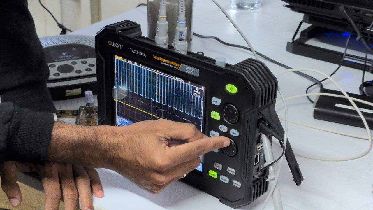
The oscilloscope used was the OWON TAO3104A.
Rotary Encoder
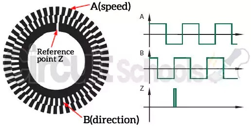
A rotary encoder is an electromechanical device that is attached to a motor or rotating shaft to accurately report position, speed, and even acceleration of the shaft.
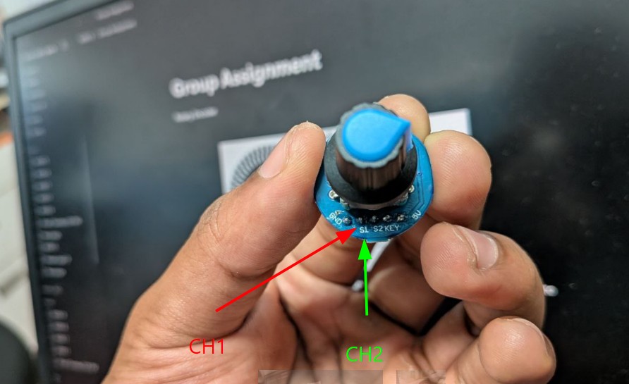
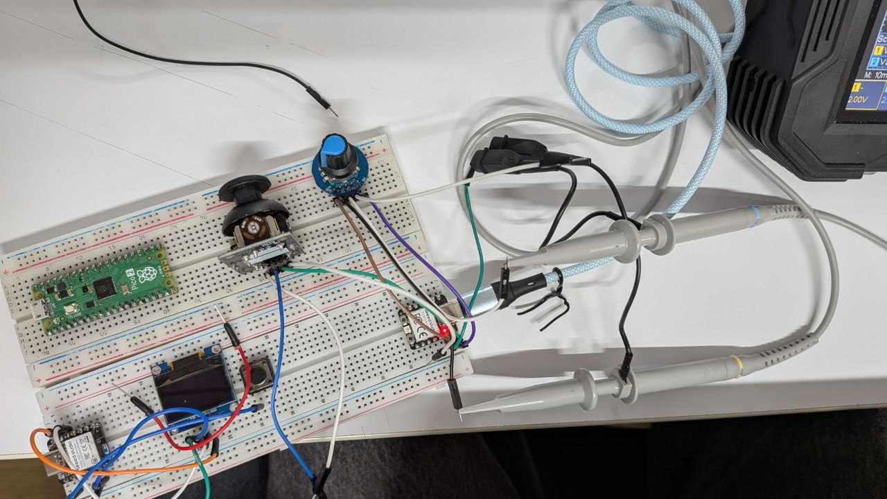
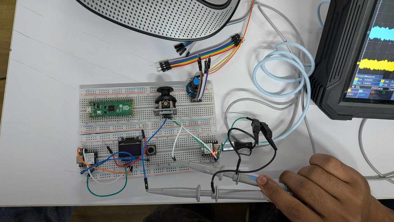
In this setup, the S1 and S2 output pins of the encoder were probed using Channel 1 and Channel 2 of the oscilloscope, with a common ground connection.
The encoder generates two signals that are offset by 90 degrees, known as quadrature signals. This phase difference allows us to determine the direction of rotation, since one signal will lead or lag the other depending on how the shaft is turned.
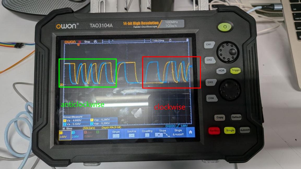
By observing how quickly these signals change, we can also determine the rotational speed. Even though the waveform may look slightly analog due to mechanical switching behavior, the encoder output is effectively digital, switching between high and low states.
Joystick
A joystick is an analog input device that typically provides two axes of movement.
In this case, it uses two output pins, VRx and VRy, to represent horizontal and vertical positions. These were probed using Channel 2 and Channel 1 of the oscilloscope respectively, with a common ground connection.
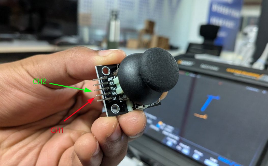
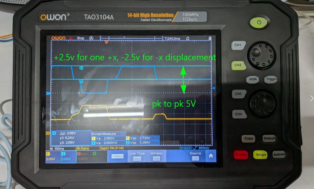
The joystick is powered using a 5V supply and internally consists of two 5 kilo-ohm potentiometers. As the joystick is moved along the X or Y direction, the resistance of these potentiometers changes, producing a corresponding voltage between 0 and approximately 5 volts.
These continuous analog signals allow precise measurement of the joystick’s position along both axes.
Individual Assignment
Introduction
Automatic Record Players
Automatic record players are designed to maintain smooth and consistent playback while minimizing unwanted vibrations and mechanical noise. The platter plays a major role in this. It is usually made heavy so that once it starts rotating, it resists small fluctuations from the motor, helping maintain a stable speed.
Different platter mats such as acrylic, rubber, cork, or felt are used not just to hold the vinyl in place through pressure, but also to damp vibrations. Each material slightly changes how vibrations are absorbed and transferred.
In belt-driven systems, the motor drives the platter through a belt. This helps absorb motor inconsistencies and isolates vibrations before they reach the stylus. In direct drive systems, the motor is directly connected to the spindle, allowing precise speed control at 33 or 45 rpm. However, this also increases the chance of motor vibrations reaching the stylus, so the motor is usually placed as far from the tonearm as possible or carefully isolated.
Phototransistor LED Pair Experiment
Track detection in some automatic record players relies on optical sensing. The idea is based on how the surface of a vinyl record reflects light differently depending on whether the stylus is over a groove or the smooth gap between tracks.
Grooves scatter light in multiple directions, which results in a weaker and more diffused reflection. In contrast, the smooth gaps between tracks reflect light more directly, producing a stronger and cleaner signal. This difference can theoretically be used to detect track boundaries.
To test this, an LED and a phototransistor pair is used. The LED illuminates the record surface, and the phototransistor measures the reflected light intensity as an analog signal. This signal can then be amplified and passed through a comparator to generate a digital output. By counting these transitions, the system could potentially detect track changes and trigger tonearm movement.
Microcontroller Used
ATtiny3226
The ATtiny3226 was used as the main microcontroller. It provides enough GPIO pins for all the sensors and inputs in this setup. It also has PWM outputs, which are useful for driving the LED, and a 12-bit ADC, which gives better resolution when reading analog signals from the phototransistor. The chip runs at up to 20 MHz, which is more than sufficient for this application.
Input Sensors Used
Hall Effect Sensor A1324
A Hall effect sensor is used along with a small magnet placed on the plinth of the record player. Every time the platter completes a rotation, the magnet passes by the sensor, generating a measurable signal.
This allows tracking of the platter’s rotational speed (RPM). The data can later be used in a feedback loop to maintain a stable speed of either 33 rpm or 45 rpm, depending on the selected mode.
IR LED and Phototransistor Sensor
This LED and phototransistor combination was intended to act as a simple optical sensor to replace a more complex camera-based system. The idea was that light would reflect differently off the grooves and the smooth gaps between tracks.
Initially, an IR LED was considered since infrared light reflects well on black vinyl. The expectation was that more light would be reflected in the smooth gaps and captured by the phototransistor, allowing detection of track boundaries.
However, SMD LEDs and phototransistors typically have a wide emission and acceptance angle, usually between 60 to 120 degrees. This causes the emitted light to spread over a larger area and the phototransistor to receive light from a wide region, reducing spatial resolution.
To deal with this, a physical housing was required to restrict the light path and improve measurement accuracy.
Rotary Encoder
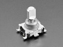
A rotary encoder is used as a user input device. It can be used to select tracks in the final system. For now, it is also used to control and toggle a user LED, mainly for testing and interaction.
Schematic Design
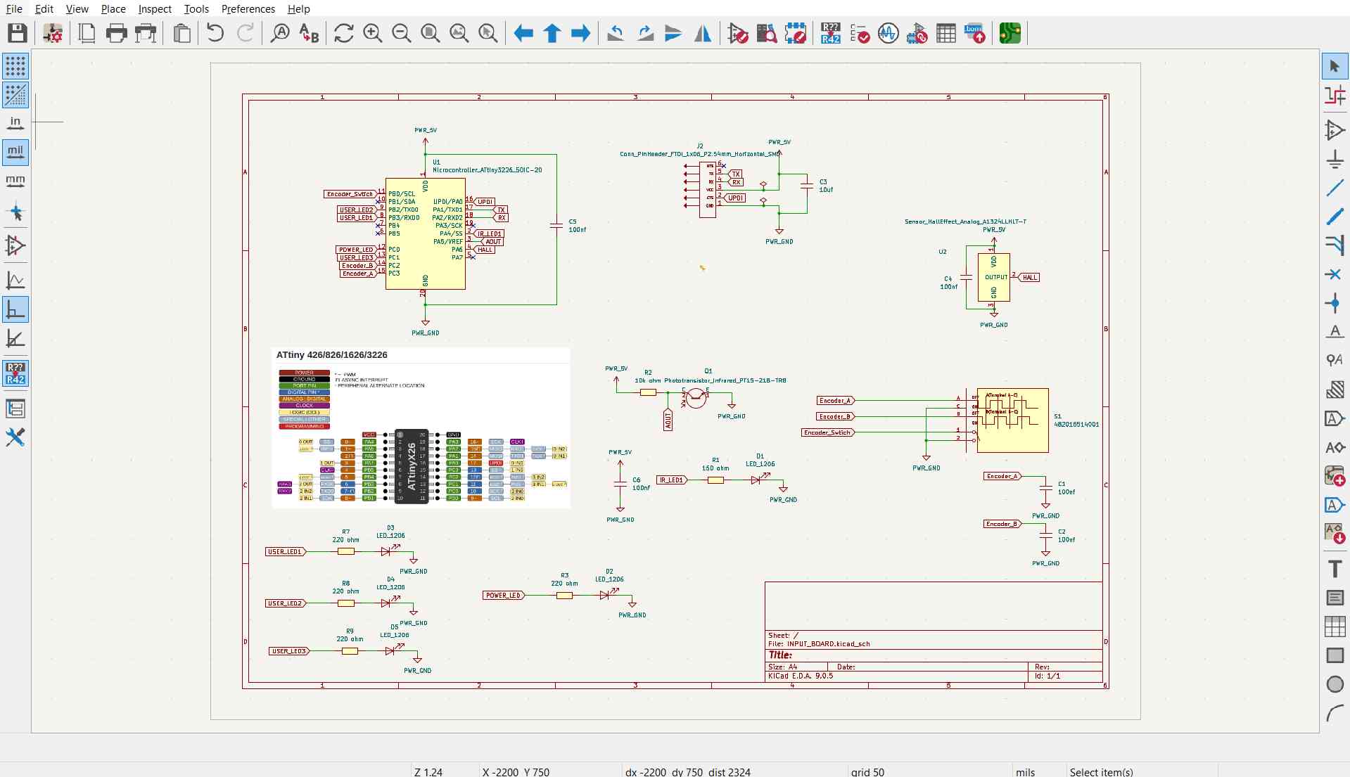
PCB Design
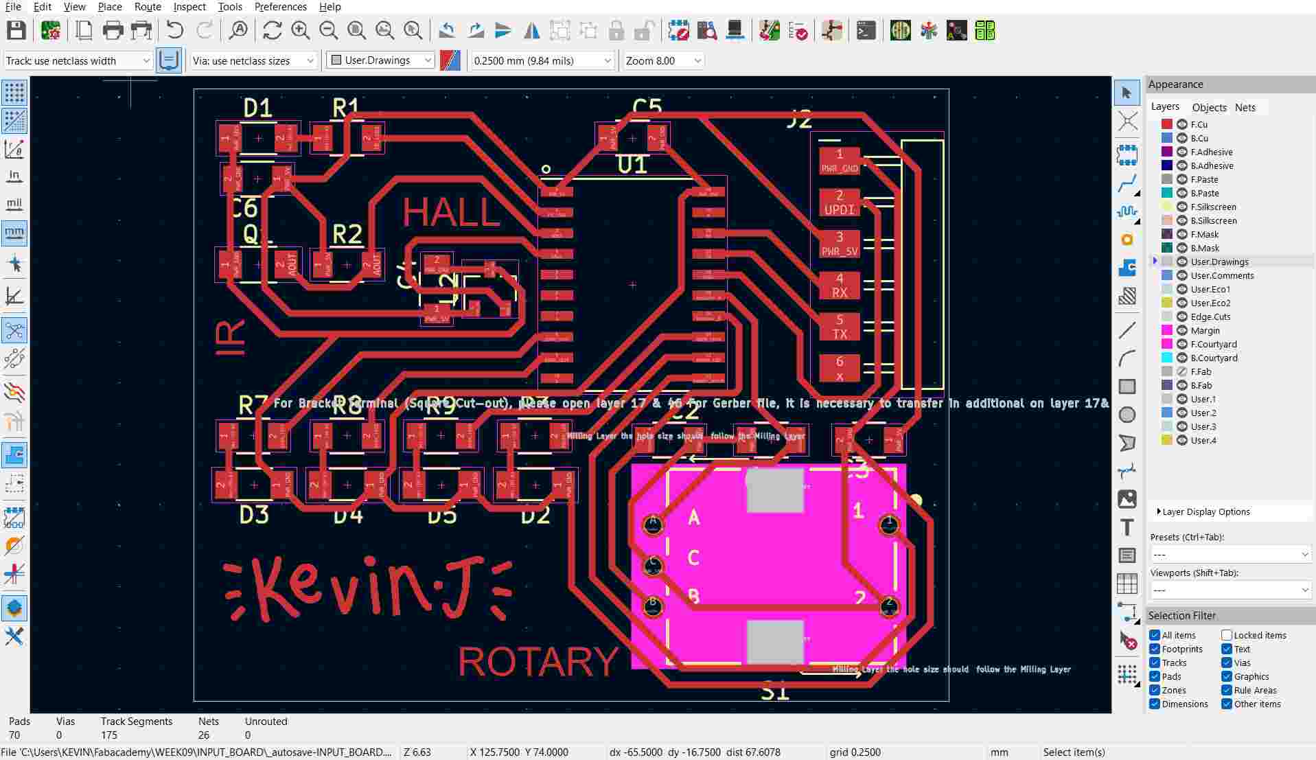
The PCB was designed as a single-sided board. At this stage, it was ready for fabrication, with plans to mill, solder, and test all input sensors.
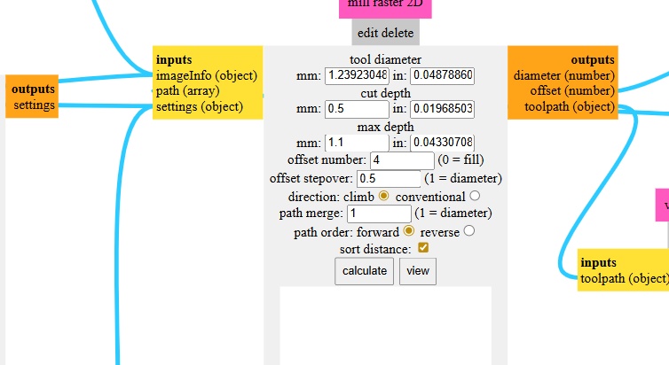
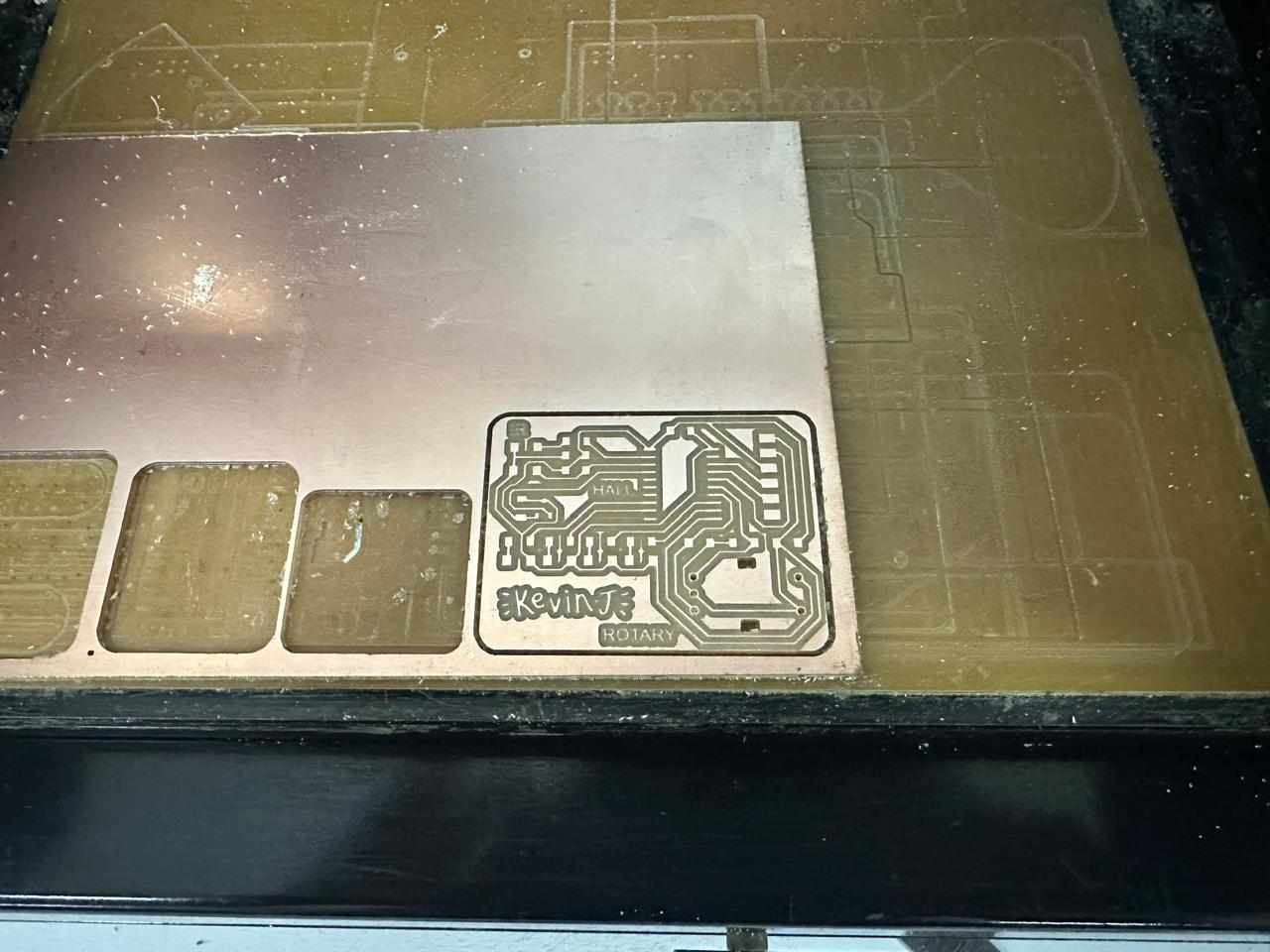
Milling, Soldering and Assembling the PCB
The PCB was milled on a single-sided copper clad plate. The copper thickness was slightly thinner than expected, so adjustments were made in the milling software. The board thickness was set to around 1.1 mm and the cutting depth to about 0.5 mm to ensure proper isolation.
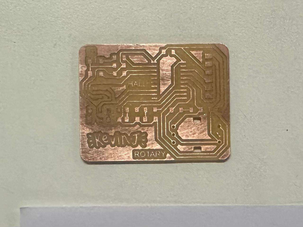
The milled board:
After milling, the adhesive underneath was cleaned using isopropyl alcohol to remove residue and ensure a clean surface for soldering.
All required components were collected from the inventory and arranged before starting the soldering process.
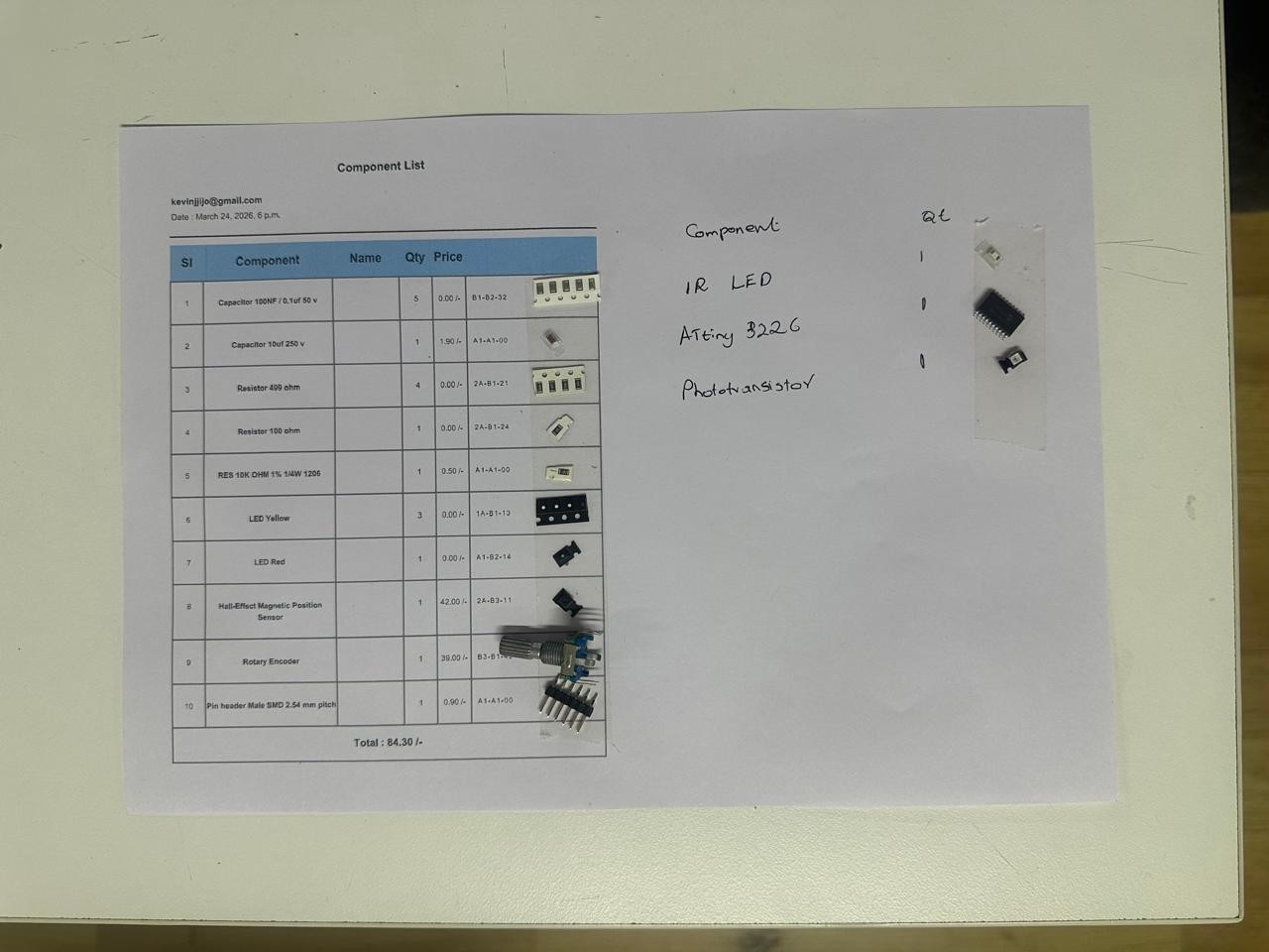
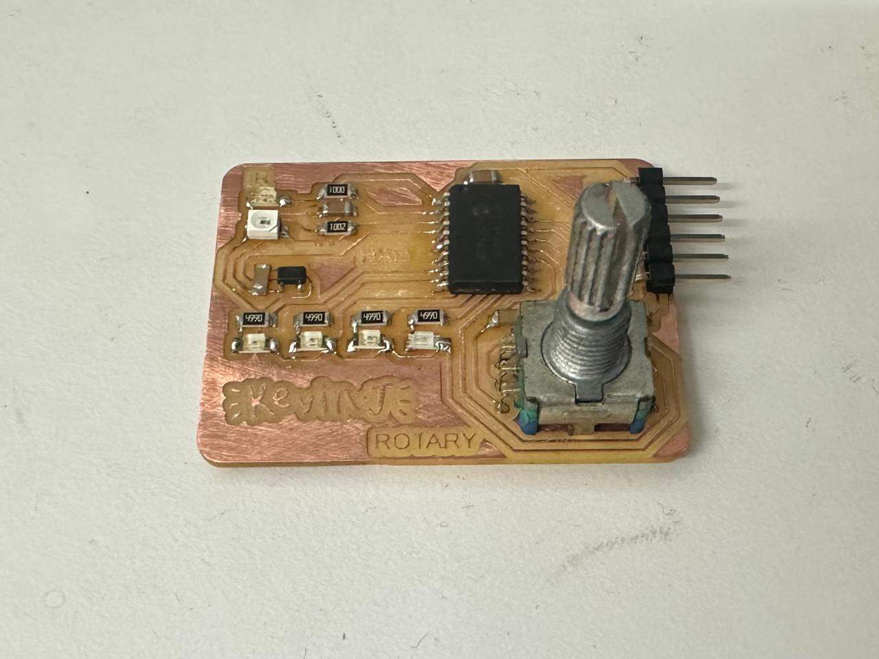
All components were then soldered onto the board.
Since the IR LED and phototransistor have a wide emission and reception angle, a housing was necessary to block ambient light and improve measurement accuracy.
The housing was designed as a flat block with two vertical through-holes for the LED and phototransistor, and a flat bottom surface to maintain a fixed distance from the record.
The design was created in Fusion.
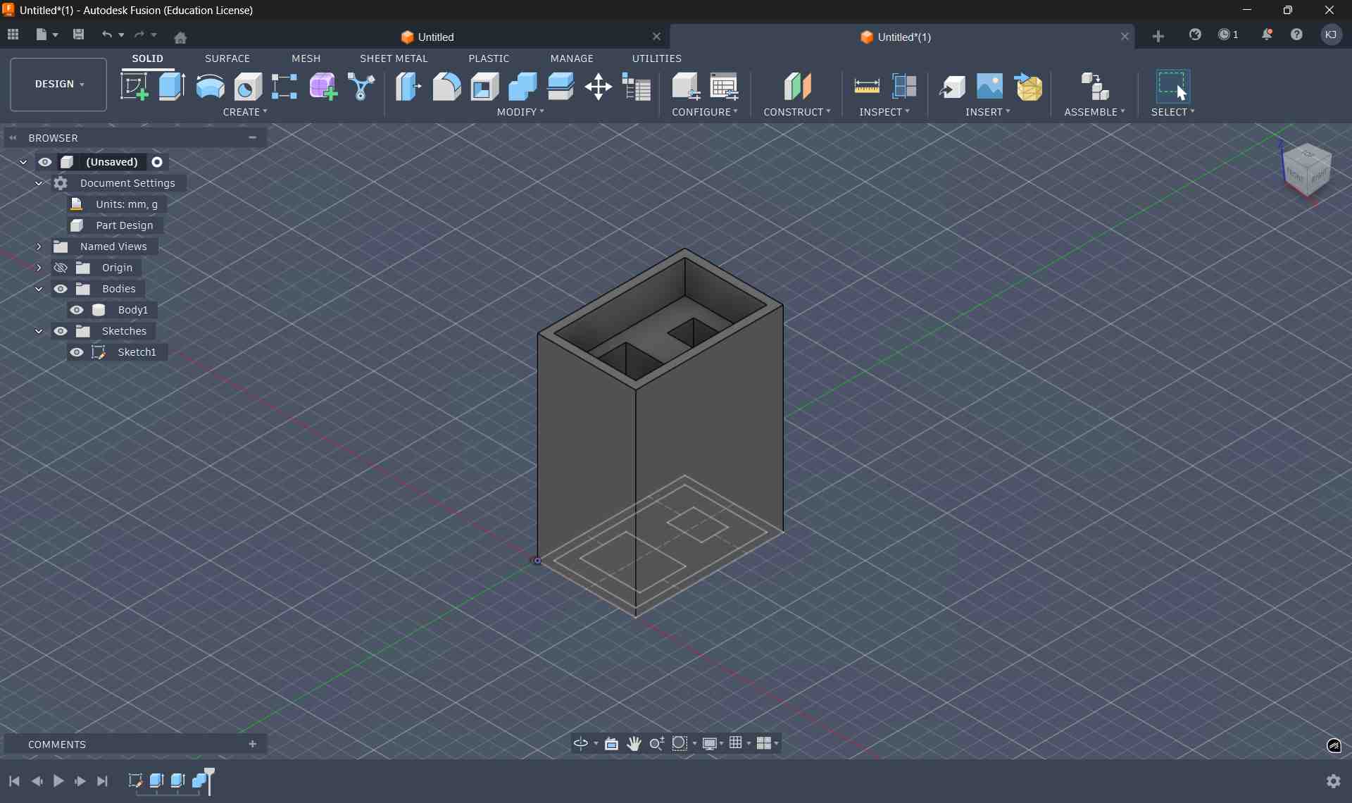
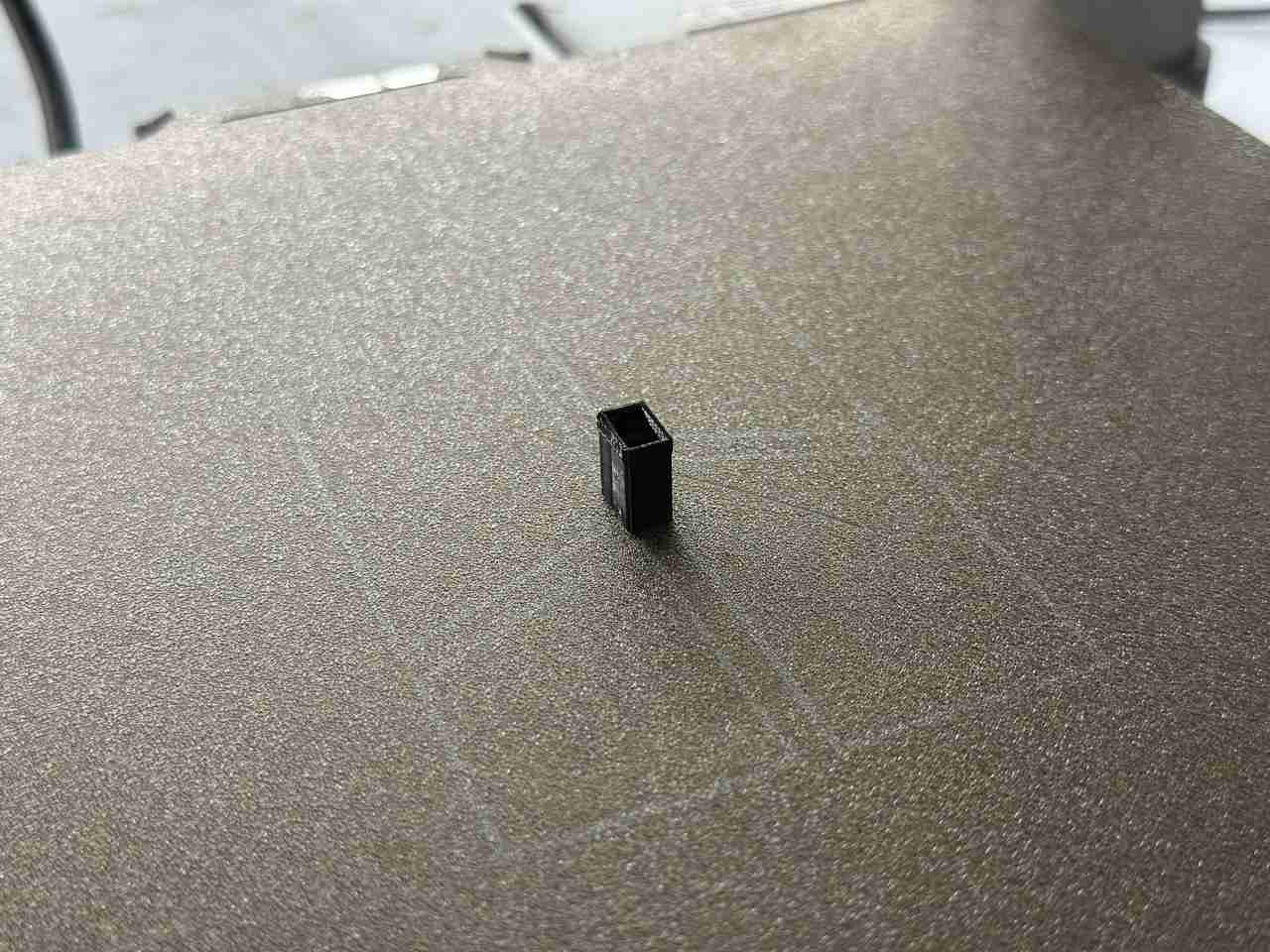
The housing was then 3D printed using black PLA on a Bambu Lab A1 printer. Black material was chosen specifically to minimize light leakage and prevent ambient light from affecting the readings.
The printed housing:
The full board assembled with the sensor housing:
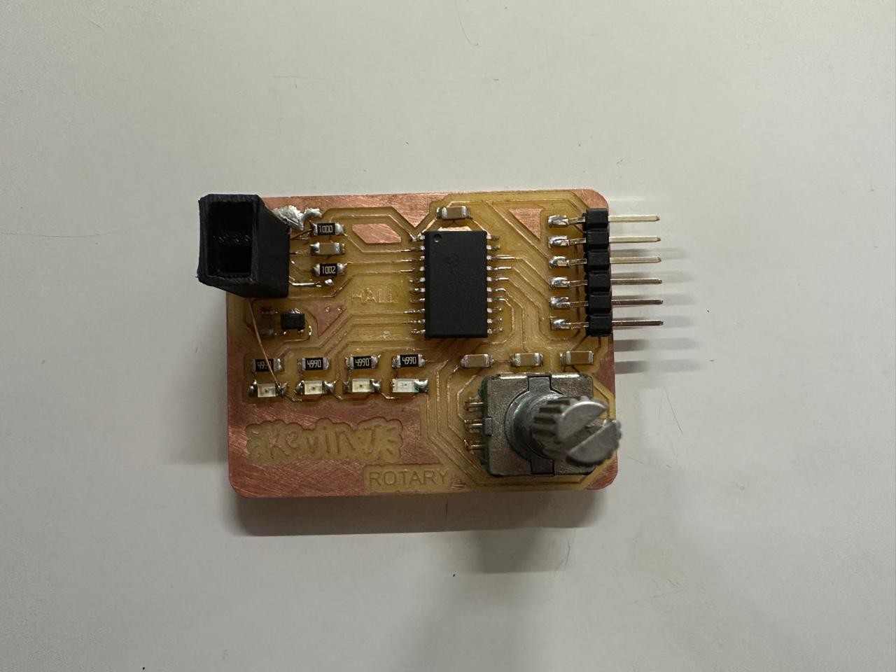
The housing effectively blocks most ambient light from reaching the phototransistor while allowing only the reflected light from the LED to be measured.
Due to availability, the phototransistor used was sensitive to visible light instead of infrared. To match this, the IR LED on the board was replaced with a visible light LED. Functionally, this should not affect the experiment since the phototransistor responds to visible wavelengths.
Testing
Each sensor and input was tested individually to verify functionality.
Phototransistor LED Pair
The phototransistor experiment did not work as expected. While the sensor was able to detect the presence of the vinyl surface, there was no noticeable variation in readings between grooves and smooth track gaps.
The code used was the examples analogINOUTserial code provided by arduino, with minor modifications to read the phototransistor output and print it to the serial monitor. The readings were consistent but did not show the expected fluctuations corresponding to track boundaries.
          const int analogInPin = 1;  // Analog input pin that the potentiometer is attached to
const int analogOutPin = 9;  // Analog output pin that the LED is attached to

int sensorValue = 0;  // value read from the pot
int outputValue = 0;  // value output to the PWM (analog out)

void setup() {
  // initialize serial communications at 9600 bps:
  Serial.begin(9600);
}

void loop() {
  // read the analog in value:
  sensorValue = analogRead(analogInPin);
  // map it to the range of the analog out:
  outputValue = map(sensorValue, 0, 1023, 0, 255);
  // change the analog out value:
  analogWrite(analogOutPin, outputValue);

  // print the results to the Serial Monitor:
  Serial.print("sensor = ");
  Serial.print(sensorValue);
  Serial.print("\t output = ");
  Serial.println(outputValue);

  // wait 2 milliseconds before the next loop for the analog-to-digital
  // converter to settle after the last reading:
  delay(2);
}
This means the setup could not reliably distinguish between different surface features, making it unsuitable for track detection in its current form.
Hall Effect Sensor
The Hall effect sensor worked as expected. It was able to detect the passing magnet consistently, making it suitable for tracking platter RPM. Below is the code used to read the Hall Sensor and print them to the Serial Monitor.
#define HALL_PIN PIN_PA6

void setup() {
  Serial.begin(9600);

  analogReadResolution(12);   // 12-bit ADC → 0–4095
}

void loop() {

  int hallValue = analogRead(HALL_PIN);

  Serial.print("Hall: ");
  Serial.print(hallValue);
  Serial.println(" / 4095");

  delay(100);
}
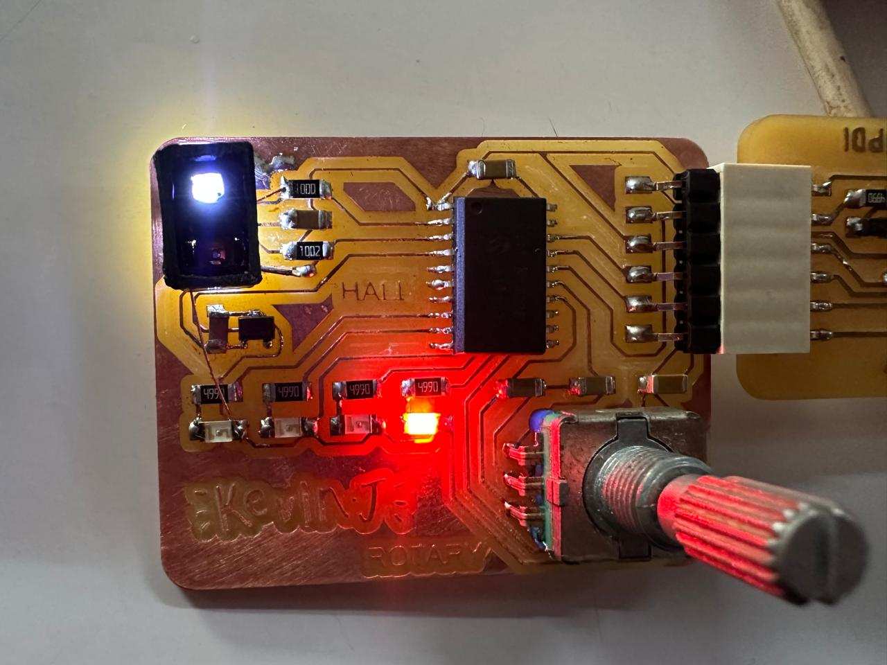
Rotary Encoder
The rotary encoder input also worked reliably. It can be used for track selection and general user interaction in the final system.
// ----- Encoder Pins -----
#define ENC_A   PIN_PC3
#define ENC_B   PIN_PC2
#define ENC_SW  PIN_PB0

// ----- LEDs -----
#define LED1 PIN_PC1
#define LED2 PIN_PB3
#define LED3 PIN_PB2

int lastA;
int ledIndex = 0;
bool powerState = true;

void setup() {

  Serial.begin(9600);

  pinMode(ENC_A, INPUT_PULLUP);
  pinMode(ENC_B, INPUT_PULLUP);
  pinMode(ENC_SW, INPUT_PULLUP);

  pinMode(LED1, OUTPUT);
  pinMode(LED2, OUTPUT);
  pinMode(LED3, OUTPUT);

  lastA = digitalRead(ENC_A);

  updateLEDs();
}

void loop() {

  // ----- ROTATION -----
  int currentA = digitalRead(ENC_A);

  if (currentA != lastA) {

    if (digitalRead(ENC_B) != currentA) {
      // CLOCKWISE
      ledIndex++;
      if (ledIndex > 2) ledIndex = 0;

      Serial.print("CW -> LED");
      Serial.println(ledIndex + 1);
    }
    else {
      // COUNTER CLOCKWISE
      ledIndex--;
      if (ledIndex < 0) ledIndex = 2;

      Serial.print("CCW -> LED");
      Serial.println(ledIndex + 1);
    }

    updateLEDs();
  }

  lastA = currentA;

  // ----- SWITCH -----
  static bool lastSwitch = HIGH;
  bool sw = digitalRead(ENC_SW);

  if (sw == LOW && lastSwitch == HIGH) {
    powerState = !powerState;

    Serial.print("Switch - Power LED: ");
    Serial.println(powerState ? "ON" : "OFF");

    updateLEDs();
    delay(200); // debounce
  }

  lastSwitch = sw;
}


// ----- LED CONTROL -----
void updateLEDs() {

  digitalWrite(LED1, LOW);
  digitalWrite(LED2, LOW);
  digitalWrite(LED3, LOW);

  if (!powerState) return;

  if (ledIndex == 0) digitalWrite(LED1, HIGH);
  if (ledIndex == 1) digitalWrite(LED2, HIGH);
  if (ledIndex == 2) digitalWrite(LED3, HIGH);
}