5. 3D Scanning and Printing
- Group assignment
- Test the design rules for your 3D printer(s)
- Document your work on the group work page and reflect on your individual page what you learned about characteristics of your printer(s)
- Individual assignment
- Design, document and 3D print an object (small, few cm3, limited by printer time) that could not be easily made subtractively
- 3D scan an object (and optionally print it)
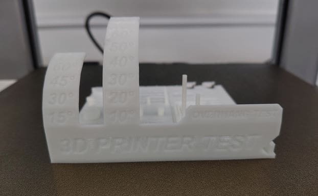
- A 25 mm long bridge started sagging, so in design, bridges up to 20 mm can be easily printed.
- For the hole test, from the given dimension, a 0.4 mm reduction was observed. This may be due to printer calibration or nozzle size.
- The scaling was quite precise in this test. All the cubes had the same dimensions in all orientations.
- For the cylinders, the actual diameters were 6 mm and 8 mm, but after printing and measuring, the dimensions were 5.74 mm and 7.75 mm respectively, showing a reduction of approximately 0.25 mm.
- From the results obtained, errors start to appear after 45 degrees.
- Clearances of 0.20 mm and 0.25 mm are sufficient for free rotation.
- A heated bed keeps the printed part adhered to the build plate
- Different materials require different bed temperatures
- PLA: ~60 °C
- PLA produces non-toxic fumes and is biodegradable (industrially), but can warp if overheated
- Filament is fed into the extruder, melted, and deposited through a nozzle
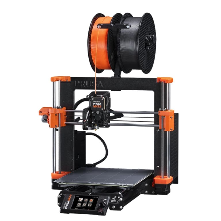
- Open-frame design
- Known for reliability and consistent print quality
- Prusa initially used off-the-shelf and open-source RepRap components, and later designed and manufactured improved in-house parts.
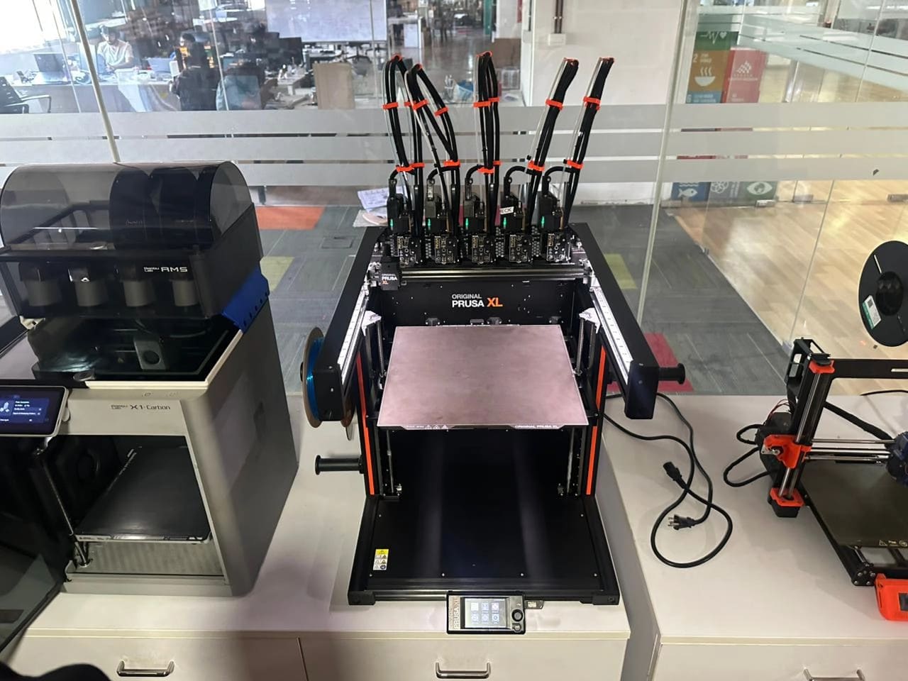
- Large-format FFF printer
- Supports up to 5 independent tool heads (extruders)
- Enables multi-material printing without purge waste
- Designed for professional and industrial applications
- Supports multiple filaments using AMS (Automatic Material System)
- Automatic filament switching for multi-color prints
- 256 × 256 resolution camera for monitoring and timelapses
- Fully enclosed for thermal stability
- Extremely high print speeds compared to traditional FFF printers
- More affordable alternative to the X1
- High-speed Core-XY motion system
- AMS support (model-dependent)
- Fewer sensors and automation features than the X1
- Similar print quality to the X1
- Known for large-format printers
- Uses separate heated beds to manage thermal expansion
- Each bed can be heated independently
- Common filament diameter: 1.75 mm
- Typically Cartesian kinematics
- Uses liquid photopolymer resin cured by UV light
- Liquid resin is toxic
- Requires gloves, ventilation, and careful handling
- Uses SLA (Stereolithography)
- Key components:
- Build platform
- Resin tank
- LPU (Light Processing Unit)
- Uses a circular laser to cure resin
- Prints upside-down
- Very smooth surface finish and high detail
- Slower than FFF
- Resolution limited by laser spot size
- Typically single-color prints
- PolyJet printing technology
- Used for realistic prototyping
- Can print multiple colors and materials simultaneously
- Extremely smooth surface finish
- Uses hundreds of microscopic nozzles
- Typical nozzle count: 200–300
- Can combine:
- Rigid
- Rubber-like
- Transparent materials in one part
Group Assignment
In the group assignment, we explored the fundamentals of 3D printing and additive manufacturing, focusing on different printer technologies such as FDM, SLA, DLP, SLS, and metal-based processes. We studied how each technology works, the energy sources involved, compatible materials, and typical applications. The group also analyzed essential design rules for 3D printing, including supports, overhang limits, bridging, wall thickness, tolerances, infill patterns, and anisotropy. To validate these concepts, we performed a comprehensive calibration test print using the Bambu Lab A1, measured the results, and documented the printer’s performance and limitations.
All details are discussed on the group assignment page.
Here are the results we gathered:
The jig we printed to find these results
Individual Assignment
FFF (Fused Filament Fabrication)
FFF is a 3D printing process where a thermoplastic filament is melted and extruded layer by layer to form a part.
1. Prusa MK3
What came first — the Prusa or its parts?
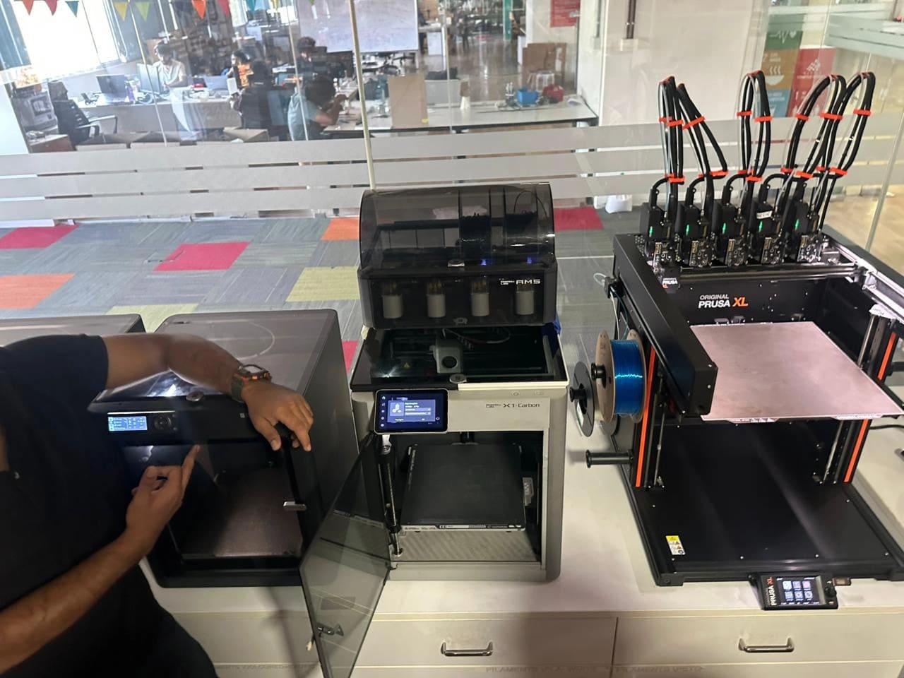
2. Prusa XL
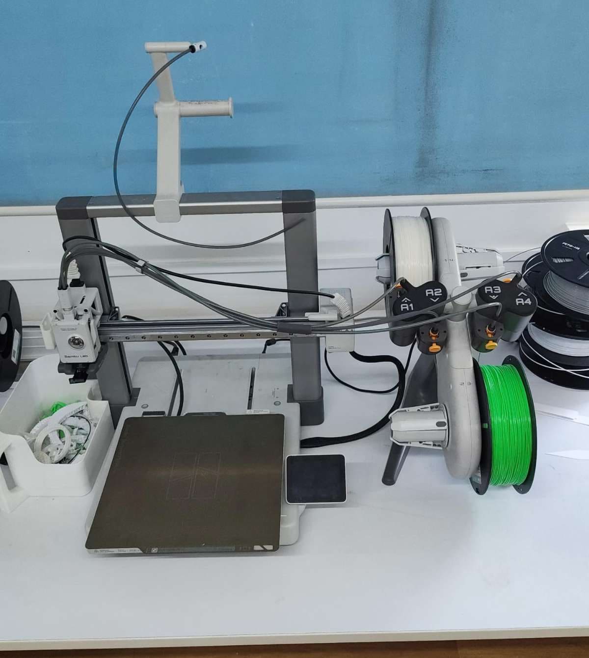
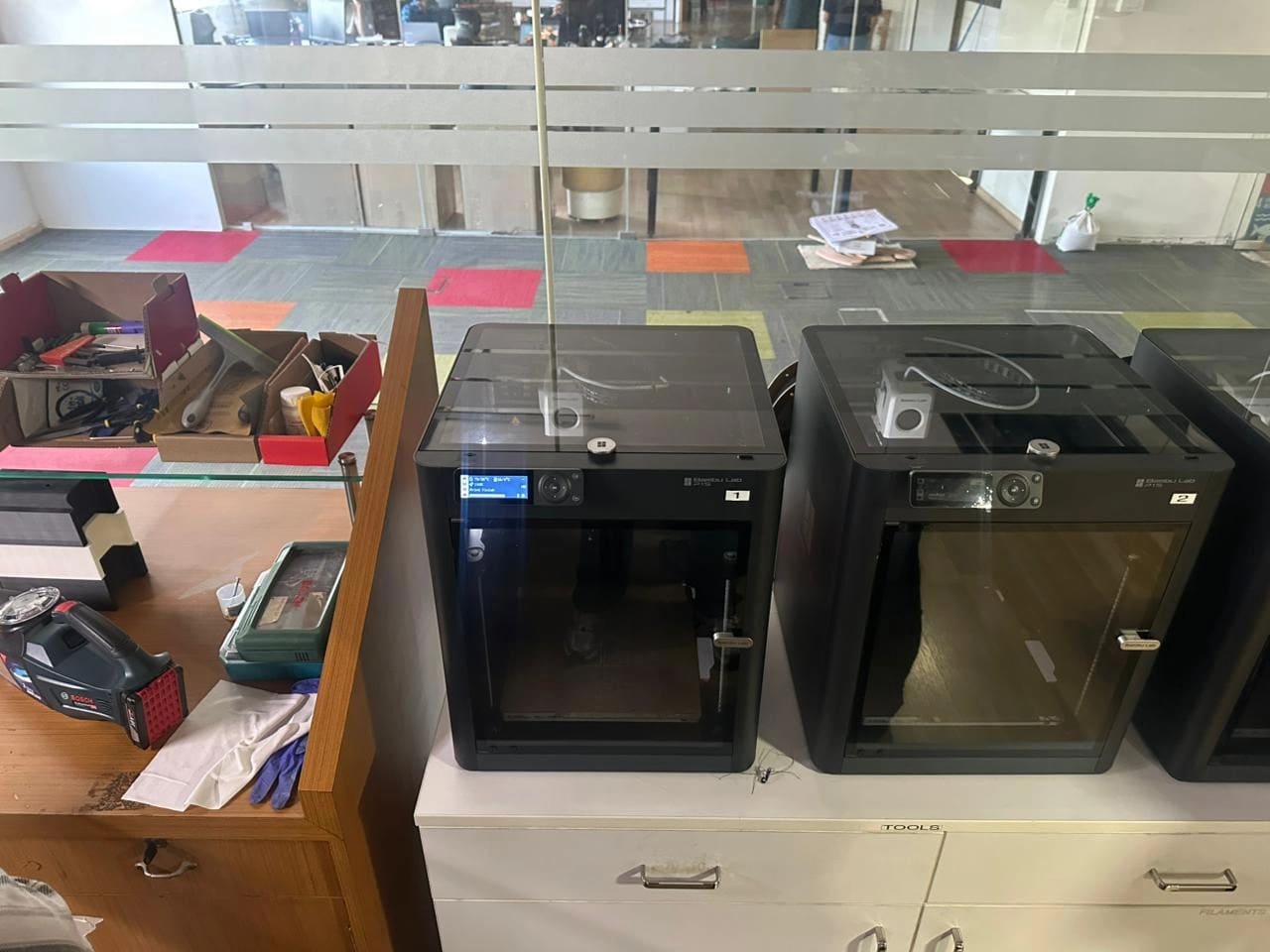
3. Bambu Lab X1
4. Bambu Lab P1
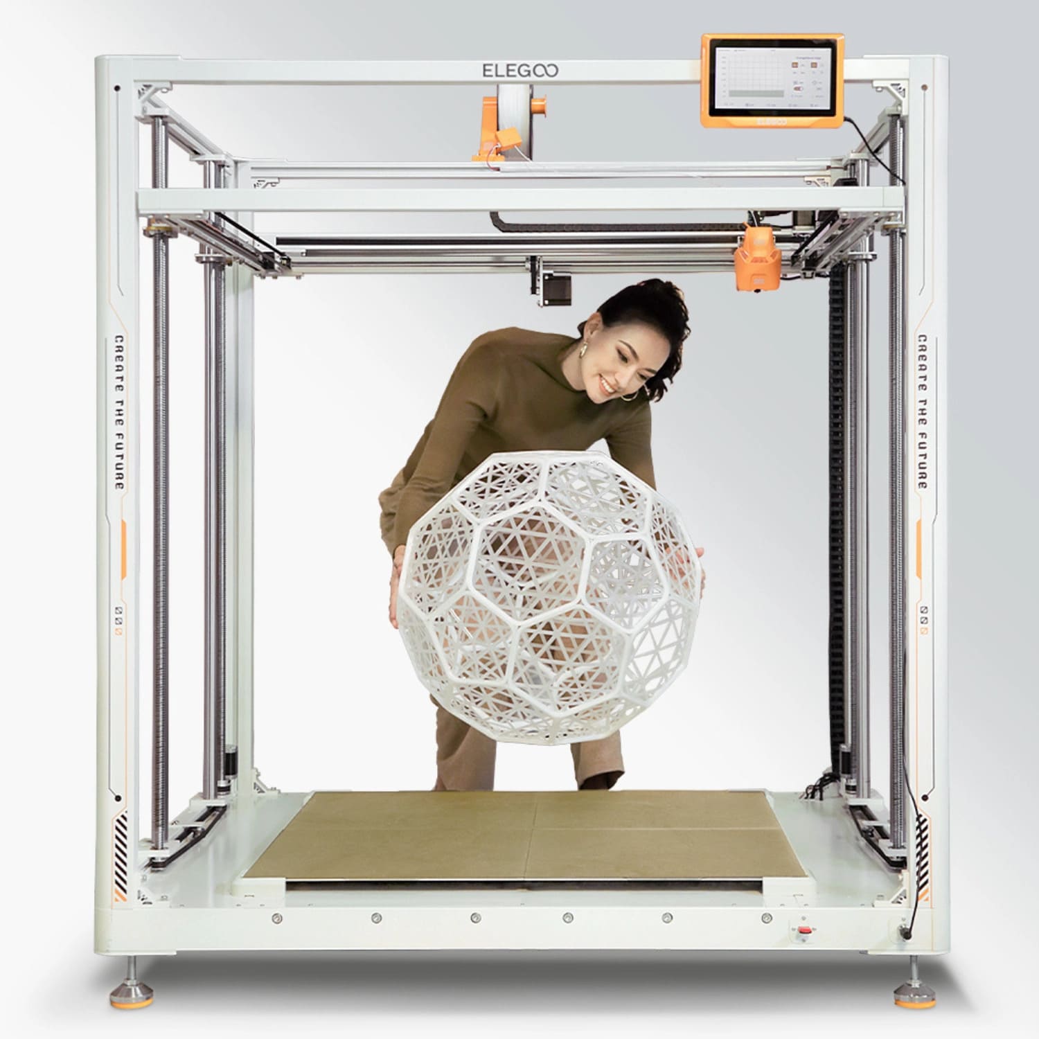
5. Elegoo
Resin Printers
Photopolymer Printing
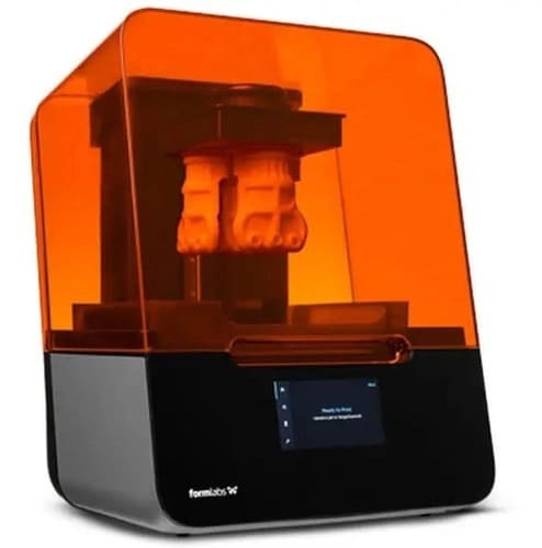
1. Formlabs Form 3
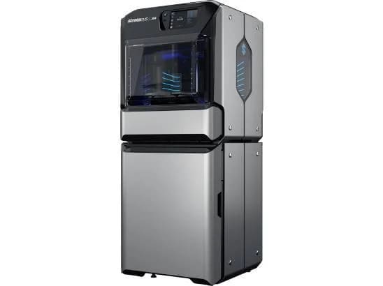
2. Stratasys J55
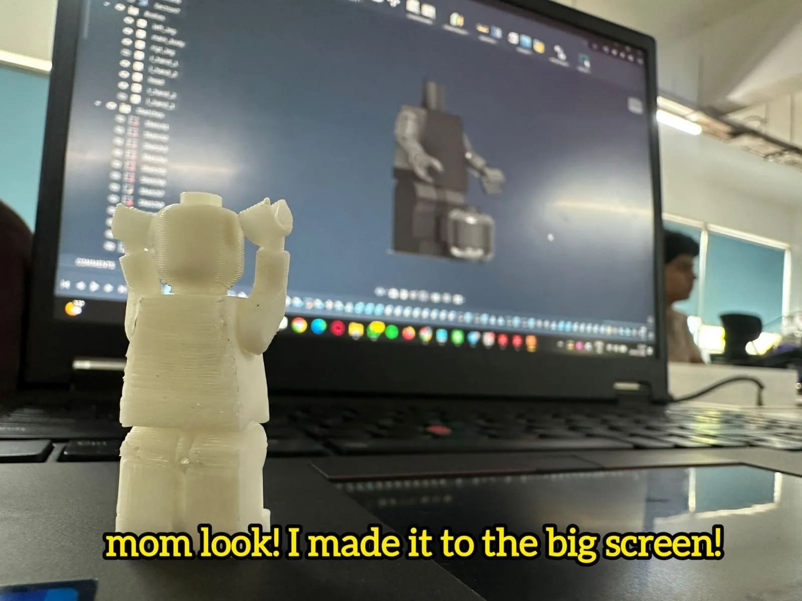
Print-in-Place LEGO Man
One of the keychains on my keys is a LEGO Superman, and I really like it. When I ride my bike, he jumps up and down and flies around like a Superman LEGO figurine should. However, I imagined those skies must get lonely for ol Supes, not to mention the dark, silent void that is my pocket with no companion. Traversing that alone must be painful.
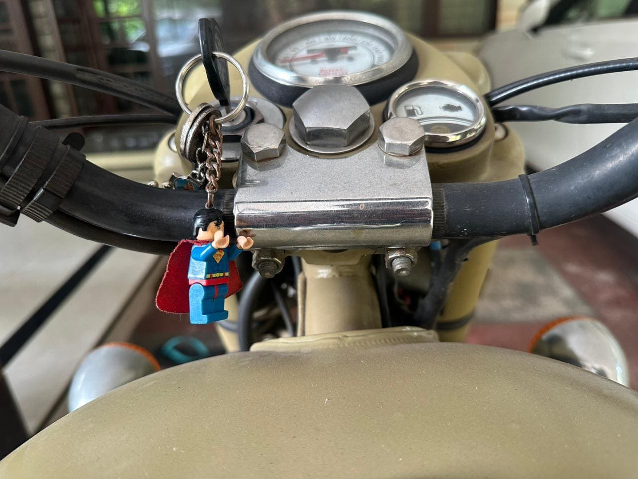
So I decided to make him a little friend.
I whipped out my vernier caliper, took exact measurements of every joint, and created a 1:1 keychain (in my case, a print-in-place model) to give him a friend, meet man-man.
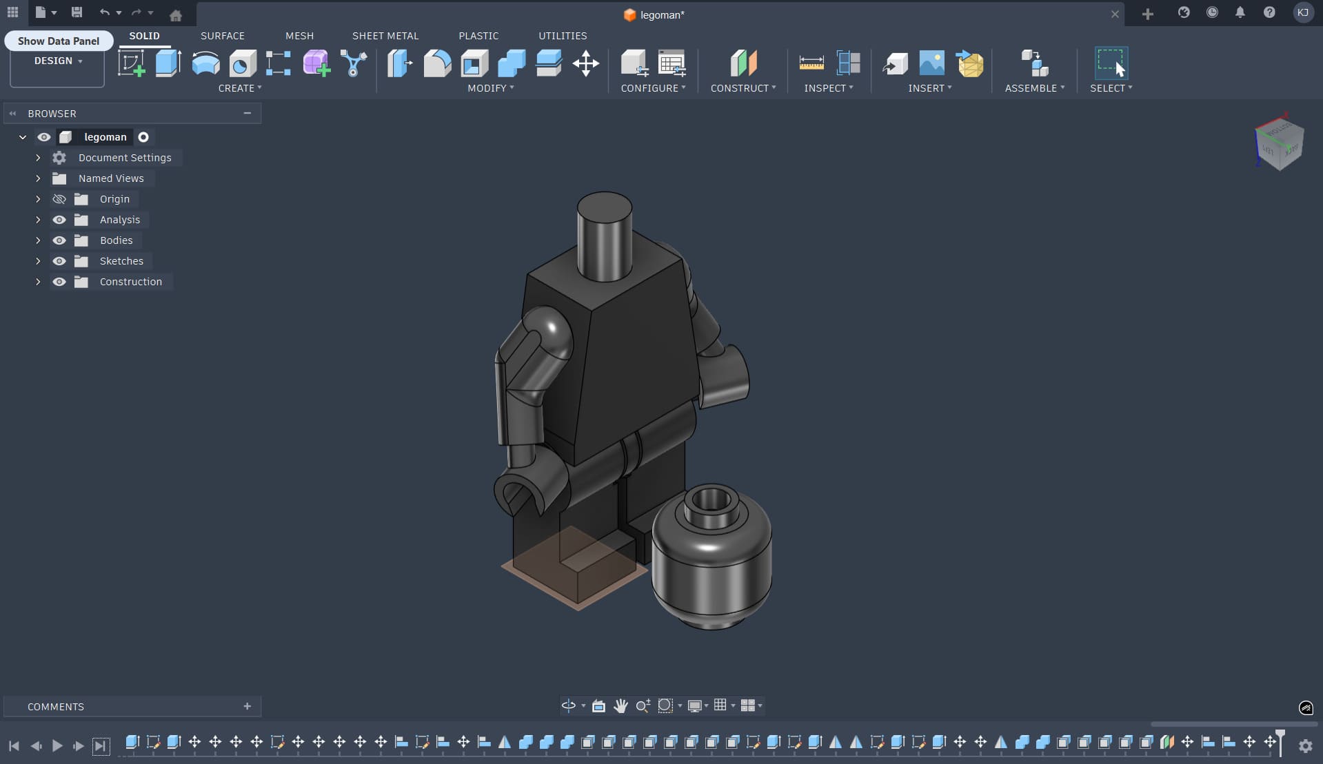
Fusion 360
The model was designed in Fusion 360, where I created a print-in-place LEGO-style figure. Instead of designing separate parts to be assembled later, I used the logic of creating empty internal chambers in the main body, into which the limbs with bulbous joint ends are printed directly. Once printed, the limbs are already captured inside the body and free to move.
Here is a timelapse of the entire design process in Fusion.
Here is the final model.
In traditional LEGO manufacturing, figures are made using injection molds, where parts are forced into place using elastic deformation. Specific regions are designed to flex so that the joints snap in and remain held under tension. I did not replicate this molding logic exactly. Instead, I wanted to demonstrate a clear advantage of additive manufacturing: the ability to fabricate assembled mechanisms in a single print, which is either impossible or extremely complex with subtractive or formative processes.
I chose not to make the hands movable. At that point in the design process, the joint clearances and internal constraints were already mentally exhausting, and adding another moving part felt like the final straw. Keeping the hands fixed allowed me to preserve my sanity while still demonstrating the core concept of print-in-place articulation.
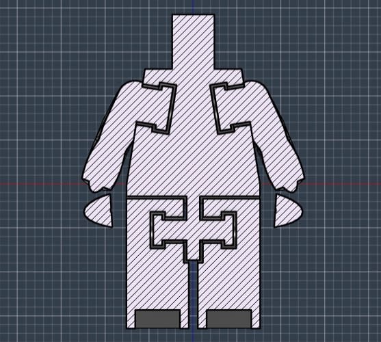
The print-in-place logic for the hands and legs.
Bambu Studio
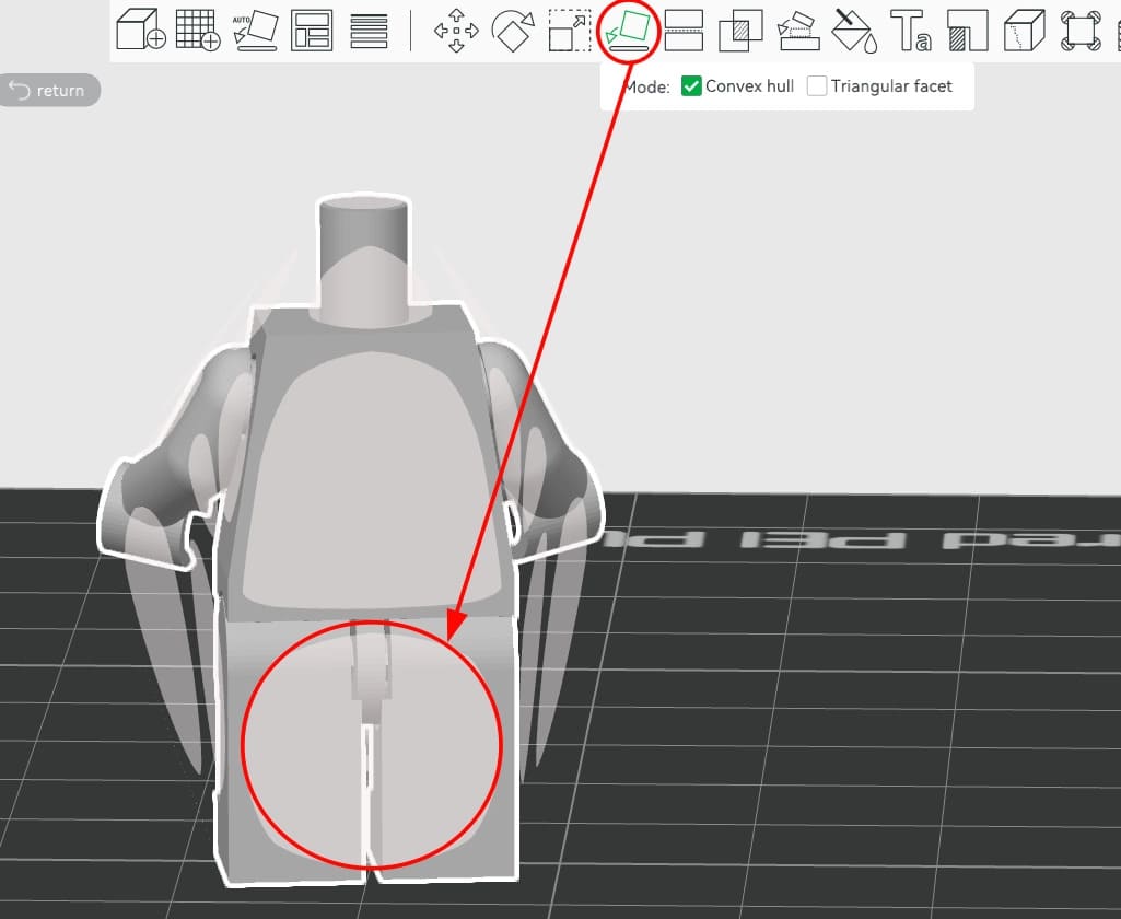
After finishing the design, I exported the model as a 3MF file and opened it in Bambu Studio. The head and body were handled as separate geometries. While arranging the parts, I noticed a design error: the legs and torso were misaligned by roughly 4 mm. Because of this, the body could not sit flat on the build plate. The only stable orientation was partially on the legs and back, which required the use of supports.
To import the parts correctly, I first opened the body 3MF file. Then, I added the head using the Add option inside the same project.
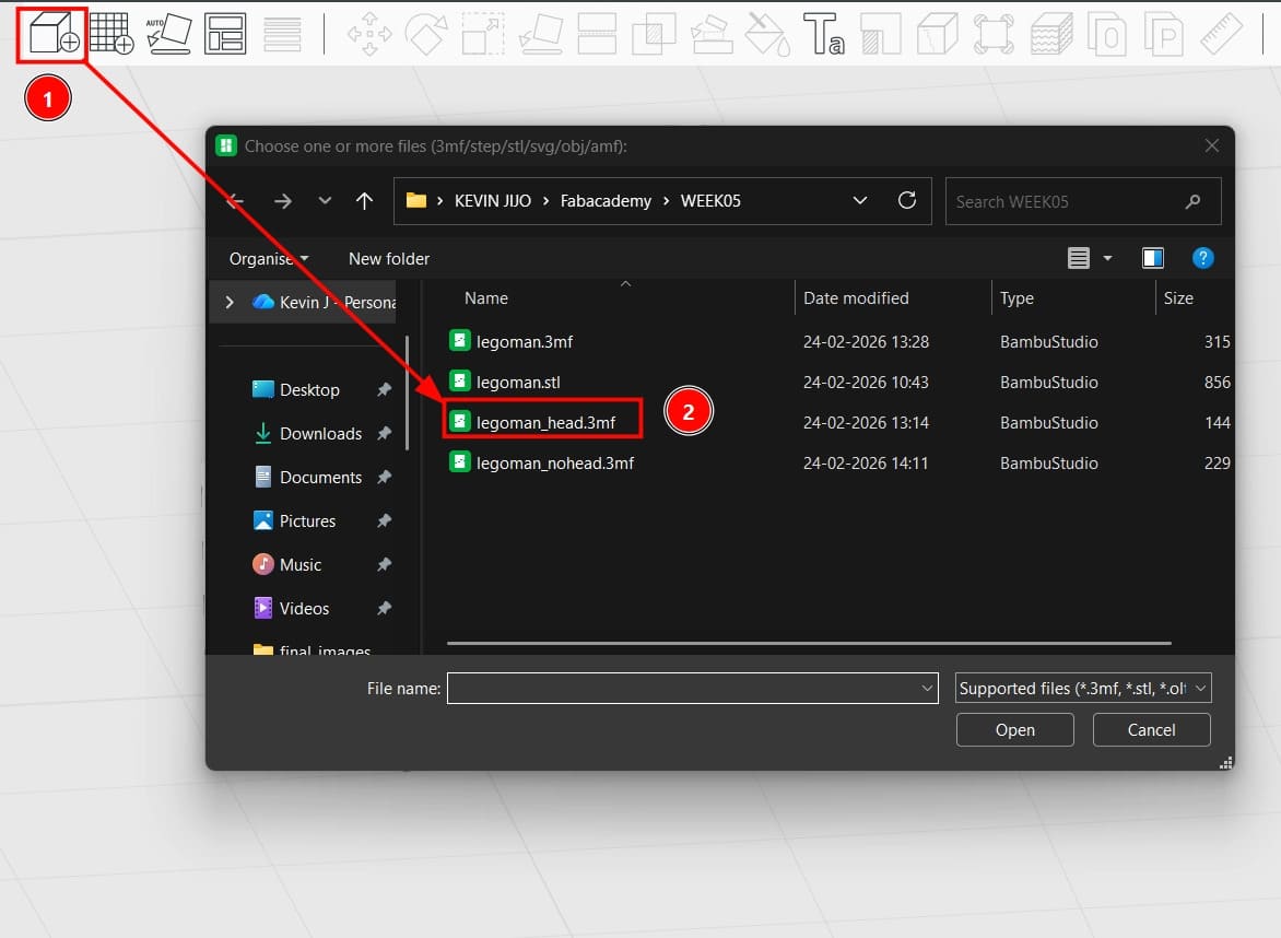
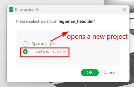
When importing the head, it is important to select “Import Geometry”. Choosing “Open as Project” would instead create an entirely new project, which is not what we want when combining multiple parts in a single print job.
Once both parts were in the same workspace, I arranged the head and body with approximately 5 mm of separation between them. After this, I used auto-orientation to let the slicer suggest a printable orientation. Because of the previously mentioned misalignment between the back and legs, the body had to be oriented resting primarily on its legs.
The head did not pose any major issues. Its geometry allowed for favorable placement, and the supports generated were minimal and clean.
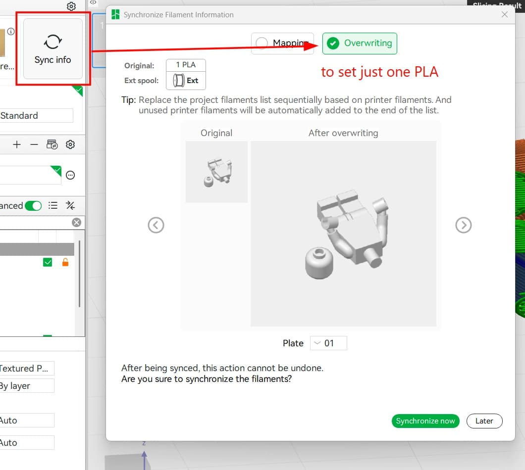
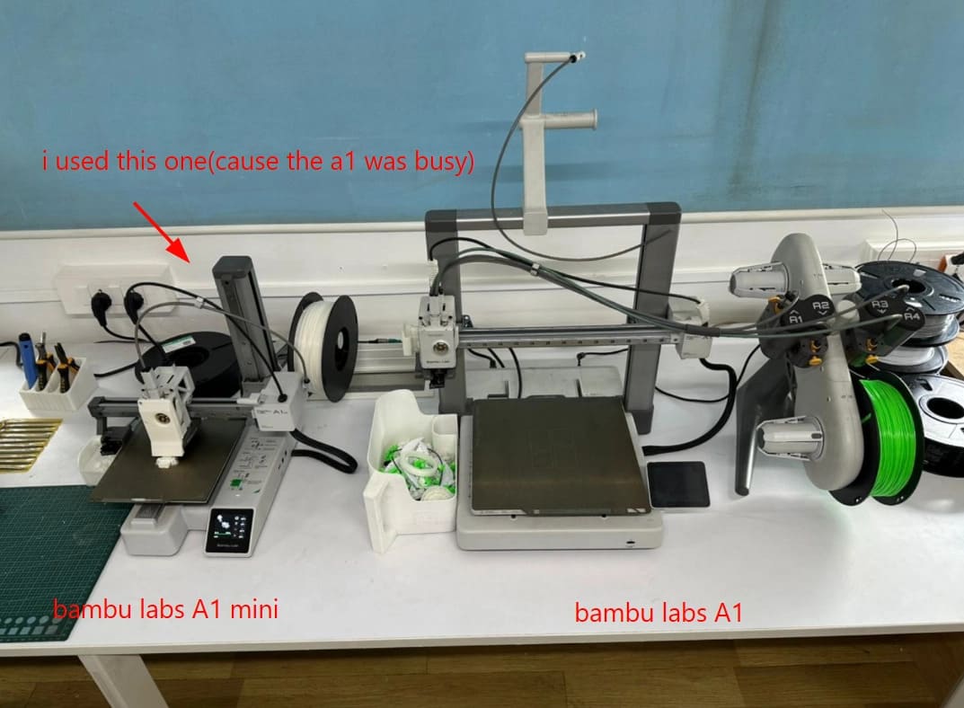
Importing the body and head separately caused Bambu Studio to automatically assign two different PLA materials. In my case, this was unnecessary, as I was working with a single spool of PLA. Additionally, the printer I was using was the Bambu Lab A1 mini, which only supports a single filament at a time. I manually reassigned both parts to the same PLA material.
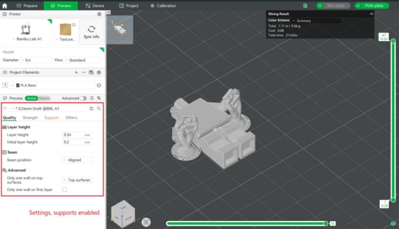
Before sending the job to the printer, I previewed the sliced layers to ensure that the joints, internal cavities, and supports were forming correctly. This step was especially important because the model relied on tight clearances for the moving joints.
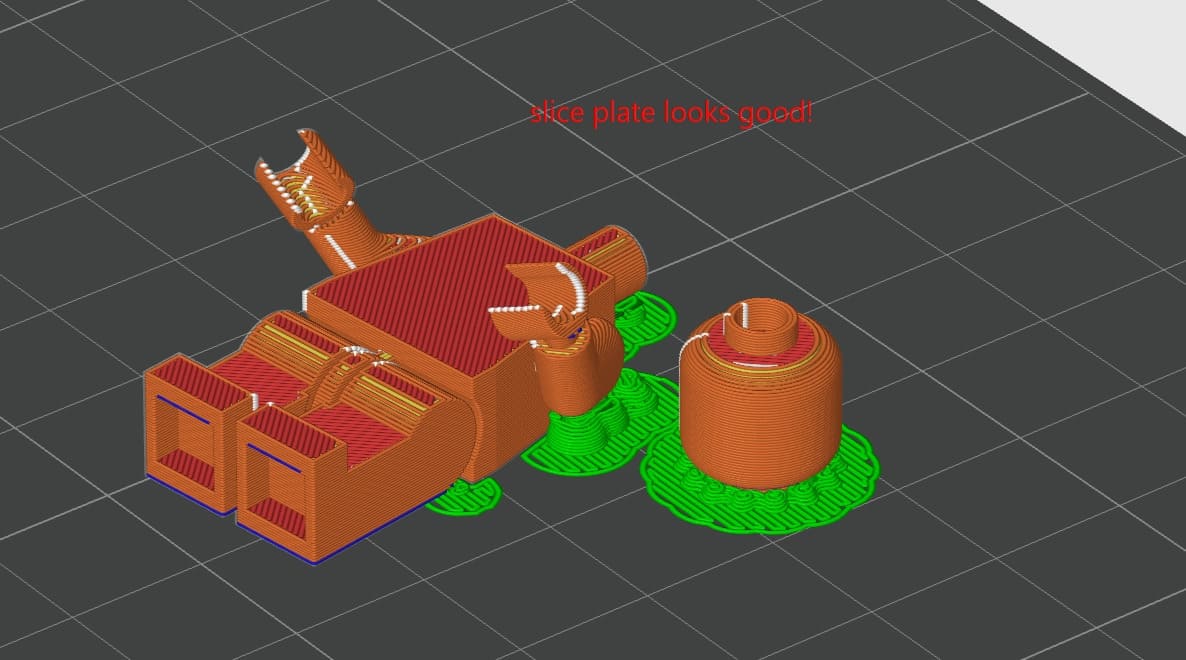
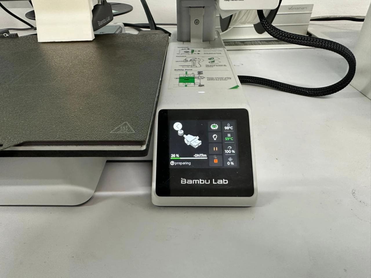
Once satisfied, the print was sent to the printer via the cloud directly from Bambu Studio.
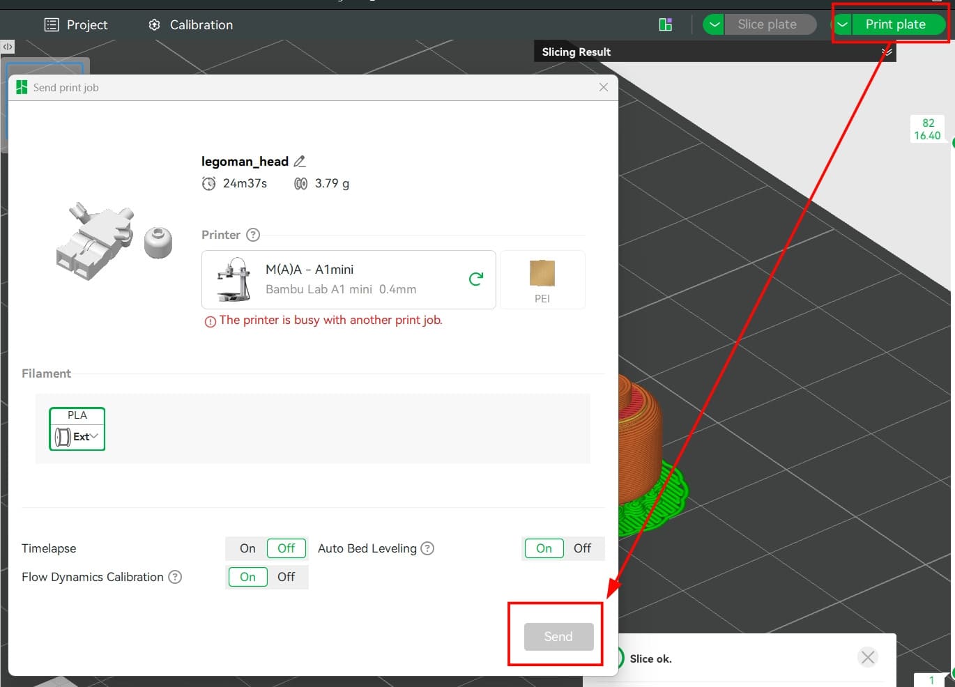
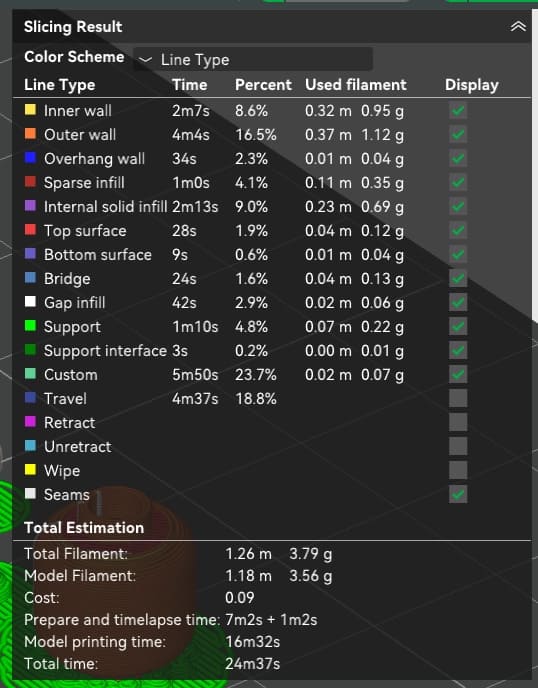
The slicing results estimated a total print time of approximately 25 minutes, with a material usage of 3.79 grams of PLA. This estimate included bed heating and nozzle warm-up. The actual printing process itself took closer to 16 minutes.
The printer used for this project was the Bambu Lab A1 mini, not out of preference, but due to availability.
The first print completed successfully in terms of surface quality and structural integrity. However, I made a critical mistake during modeling: I did not add sufficient clearance in the arm joints. As a result, the arms fused to the body and could not move.
To fix this, I returned to Fusion 360, increased the joint clearance slightly, and prepared the printer for a second attempt.
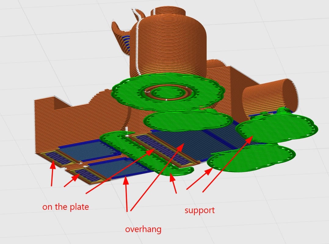
During the reprint, I encountered another issue. Initially, I tried placing the body on its back to reduce the number of visible support marks. However, due to the same misalignment between the torso and legs, this orientation caused the backs of the feet to become overhangs.
Bambu Studio generated supports, but the overhang geometry repeatedly caused print failures, with the layers not adhering properly.
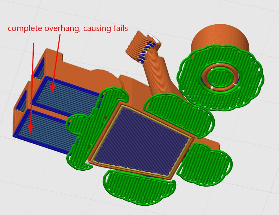
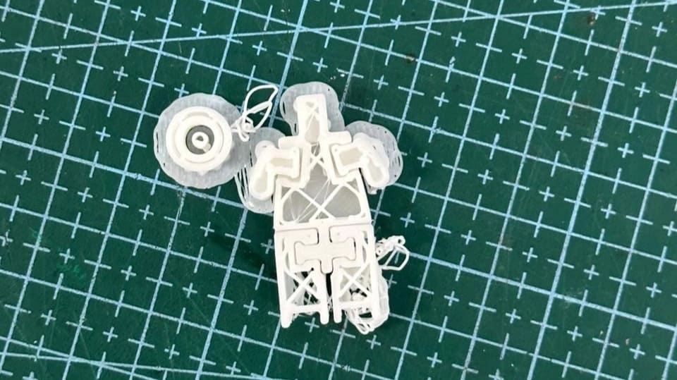
This resulted in a failed print and a very painful loss.
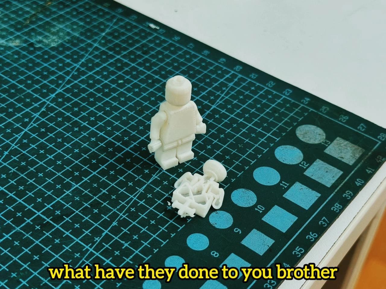
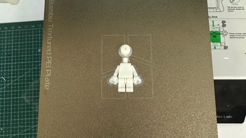
After this failure, I reoriented the model to sit on its legs, even though this meant the supports would be more visible. While this orientation was not aesthetically ideal, it was mechanically stable, and the print completed successfully.
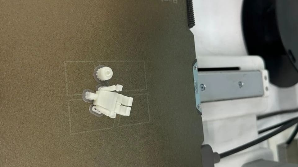
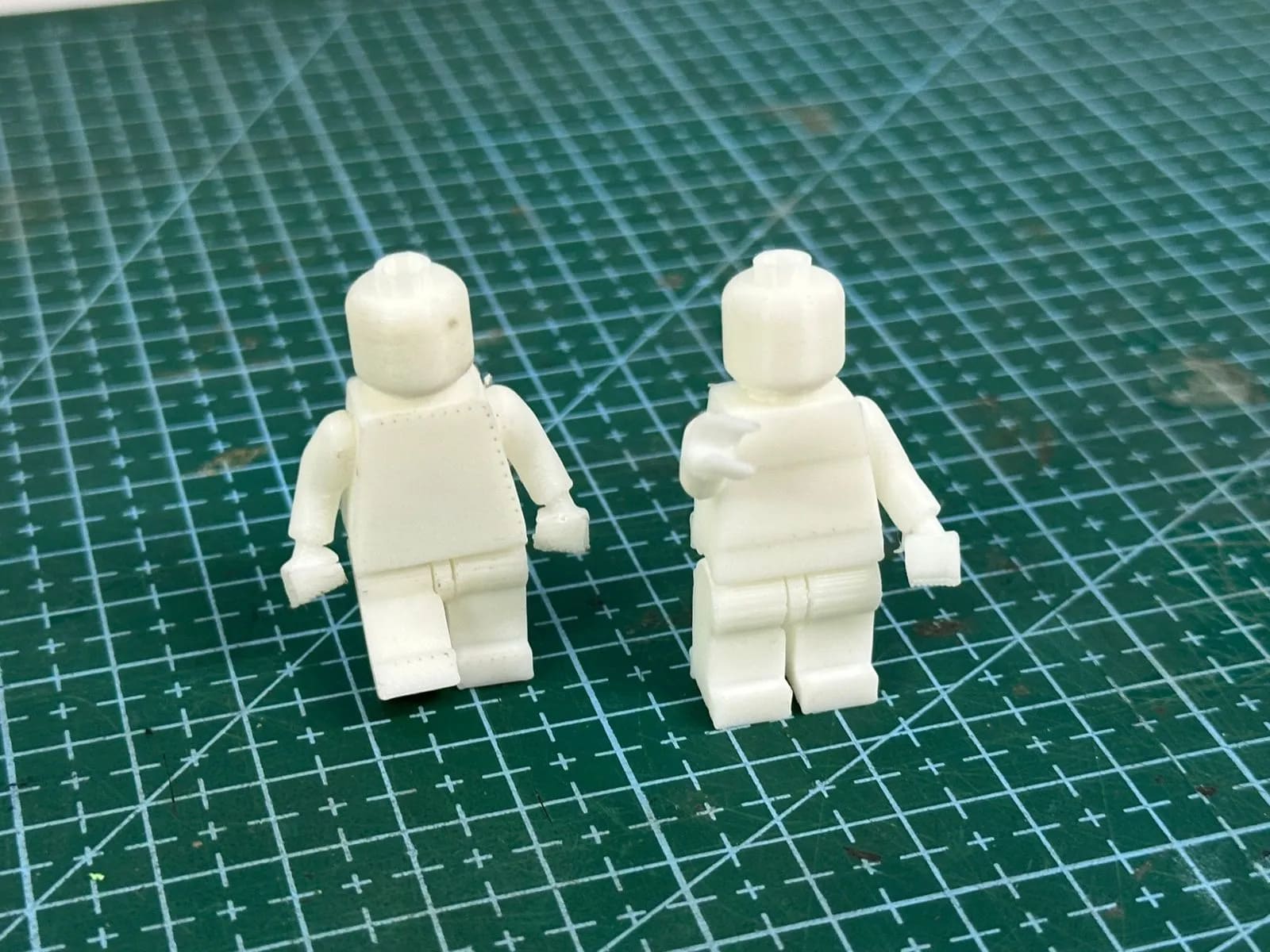
Post-processing involved removing the supports and cleaning the back surface where the model contacted the build plate. Despite the earlier issues, the final result came out clean, and most importantly, the arm joints moved freely as intended.
Comparing the first print and the final print, the improvement was clear. The adjusted joint clearance allowed smooth articulation, and the print-in-place concept worked exactly as planned.
3D Scanning
For scanning, we used the Artec Leo handheld 3D scanner from Artec 3D. Complementing the scanner is Artec Studio, the accompanying processing software. Artec Studio provides advanced tools for refining and perfecting 3D scans, allowing raw scan data to be transformed into highly accurate and detailed models. Together, the scanner and software form a comprehensive 3D scanning solution that combines ease of use with professional-grade accuracy and versatility.
.jpg)
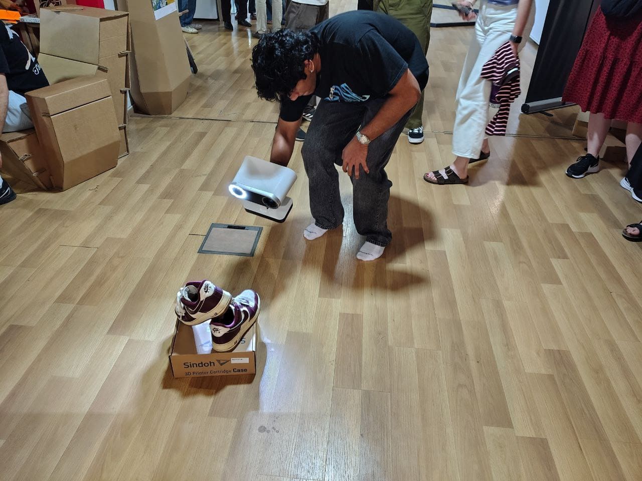
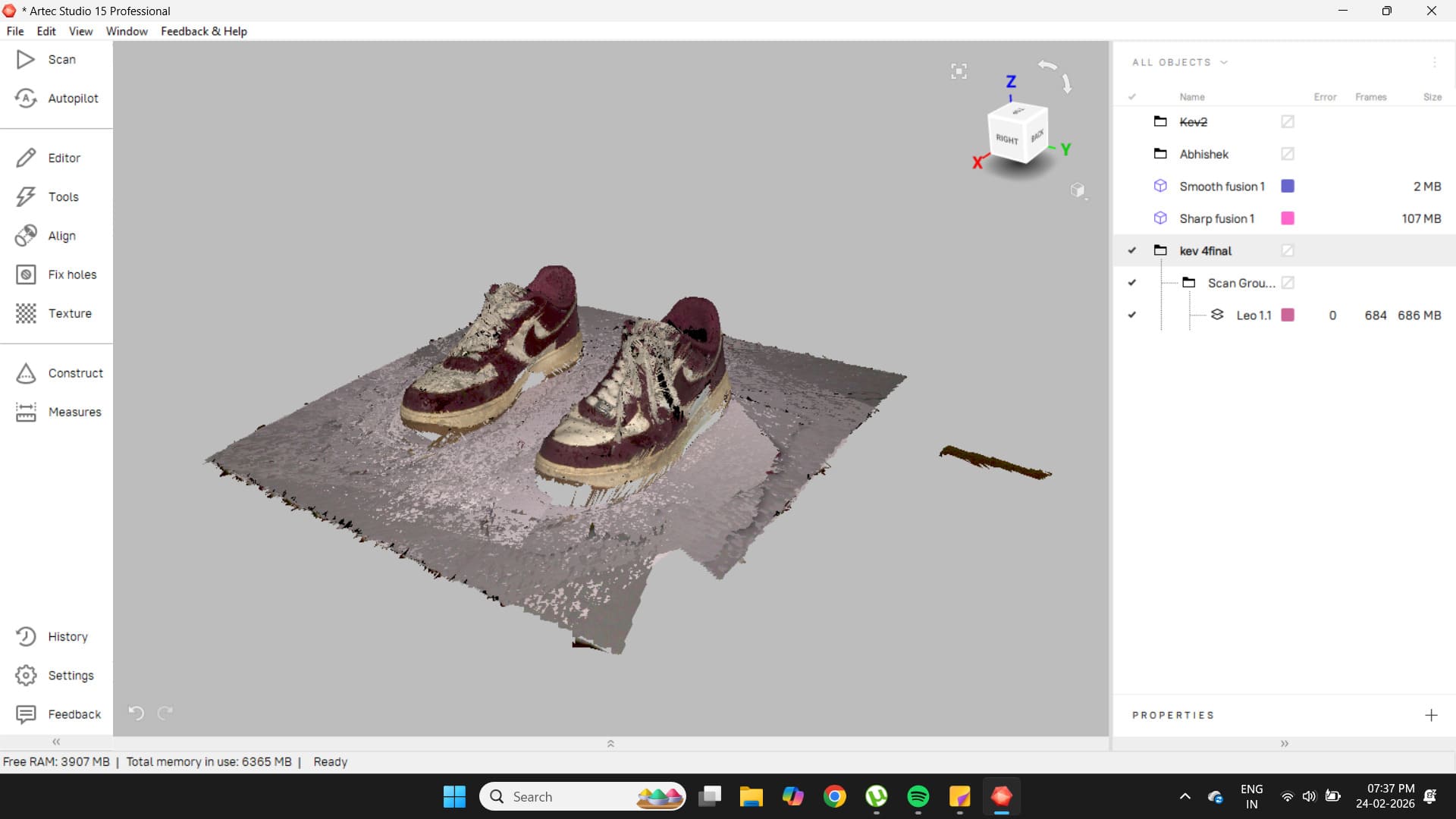
This setup can be used for reverse engineering, modeling existing objects, building virtual environments, and even digital archiving. One such use case was archiving my favorite pair of sneakers, which are nearing the end of their lifespan. I decided to preserve them digitally in all their glory.
For scanning, the shoe was placed on an elevated surface to allow easy access from all angles. I then enabled the base removal feature on the scanner, which prevents data capture below a specified height. This helped eliminate unnecessary background geometry.
After capturing the entire model, the Artec Leo interface highlighted low-quality scan areas in red. I spent additional time scanning these regions to improve data quality. However, I noticed that in deep grooves between the laces and inside the shoe, the scanner struggled to capture detail. In these shadowed regions, the projected laser light became trapped and was not properly reflected back to the sensors, resulting in lower-quality scans.
Post Processing
Connect the Artec Leo to your PC using an Ethernet cable. Then, in File → Import, select the Artec Leo if the connection was established properly. Choose your model and import it.
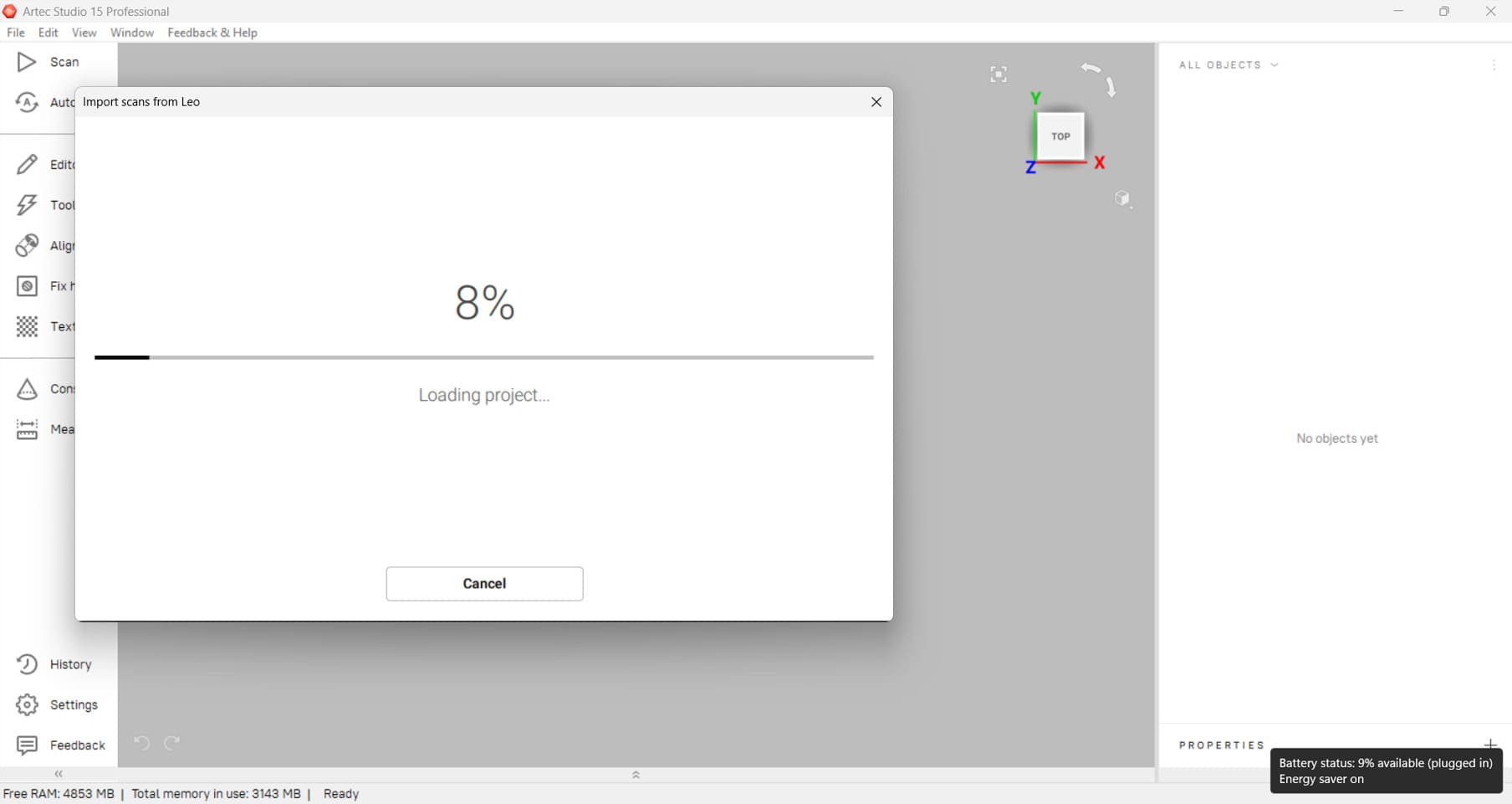
The model will appear on the right side, where all the scans captured for the object can be seen. From these, select the best scans for post-processing.
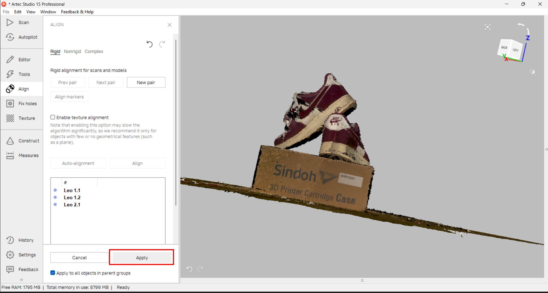
There were many scan iterations taken, so to address this, the Align tab was used to align the various scans.
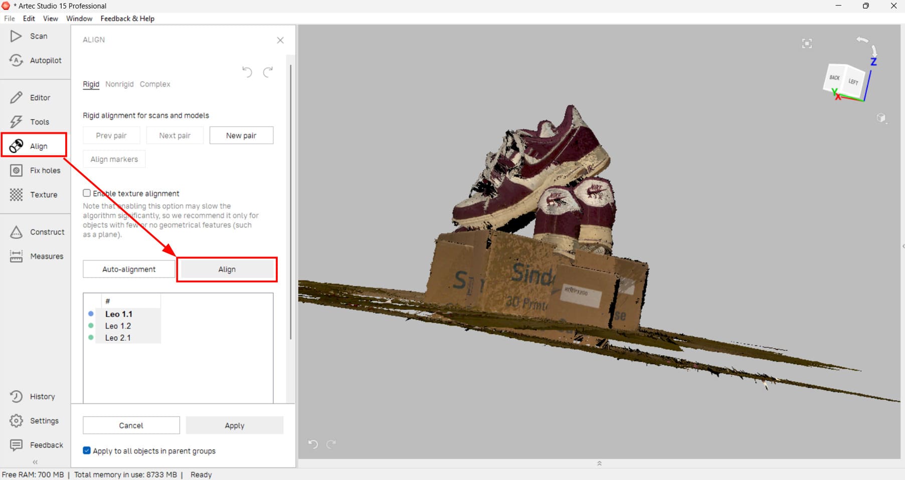
After alignment, a clearer scan was obtained.
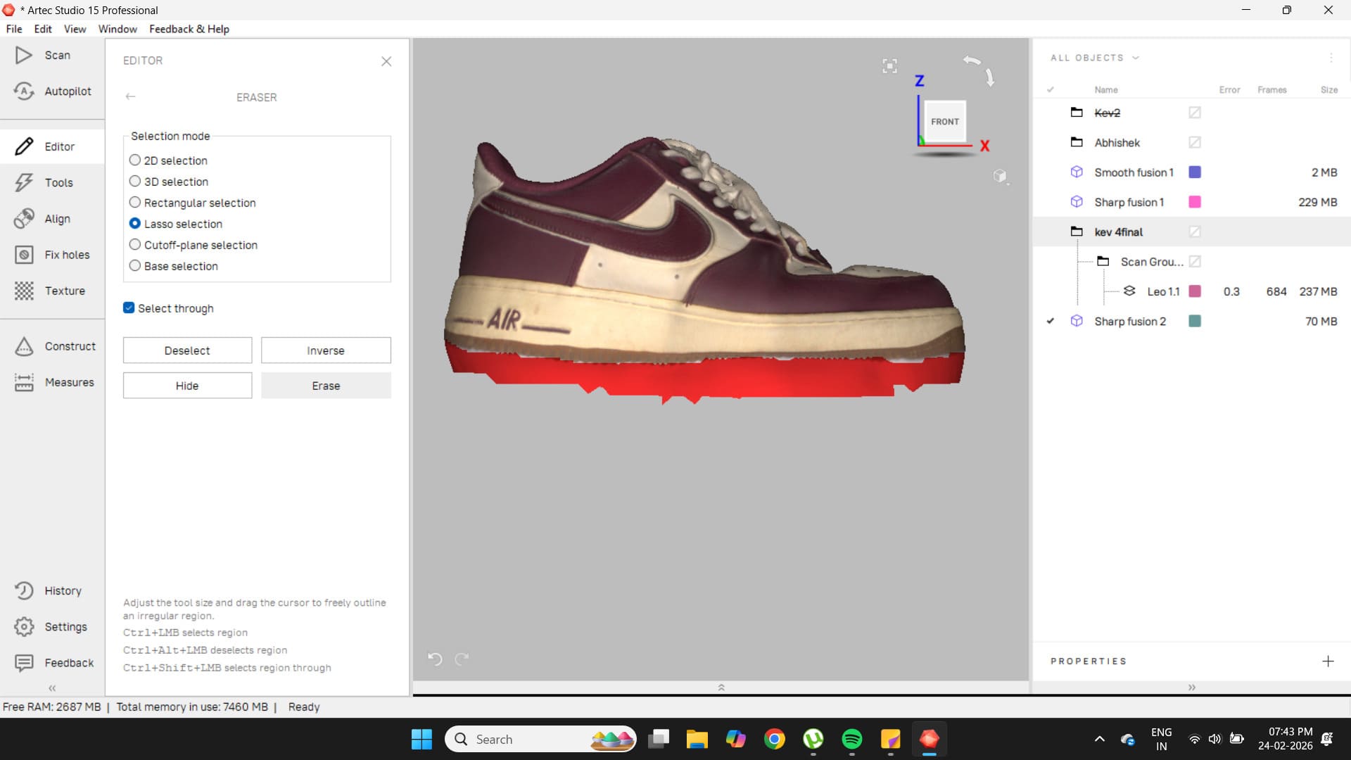
In this particular scan, base removal was not used during scanning, so it had to be done later in post-processing. To do this, the Editor tab was opened and the base removal option was selected.
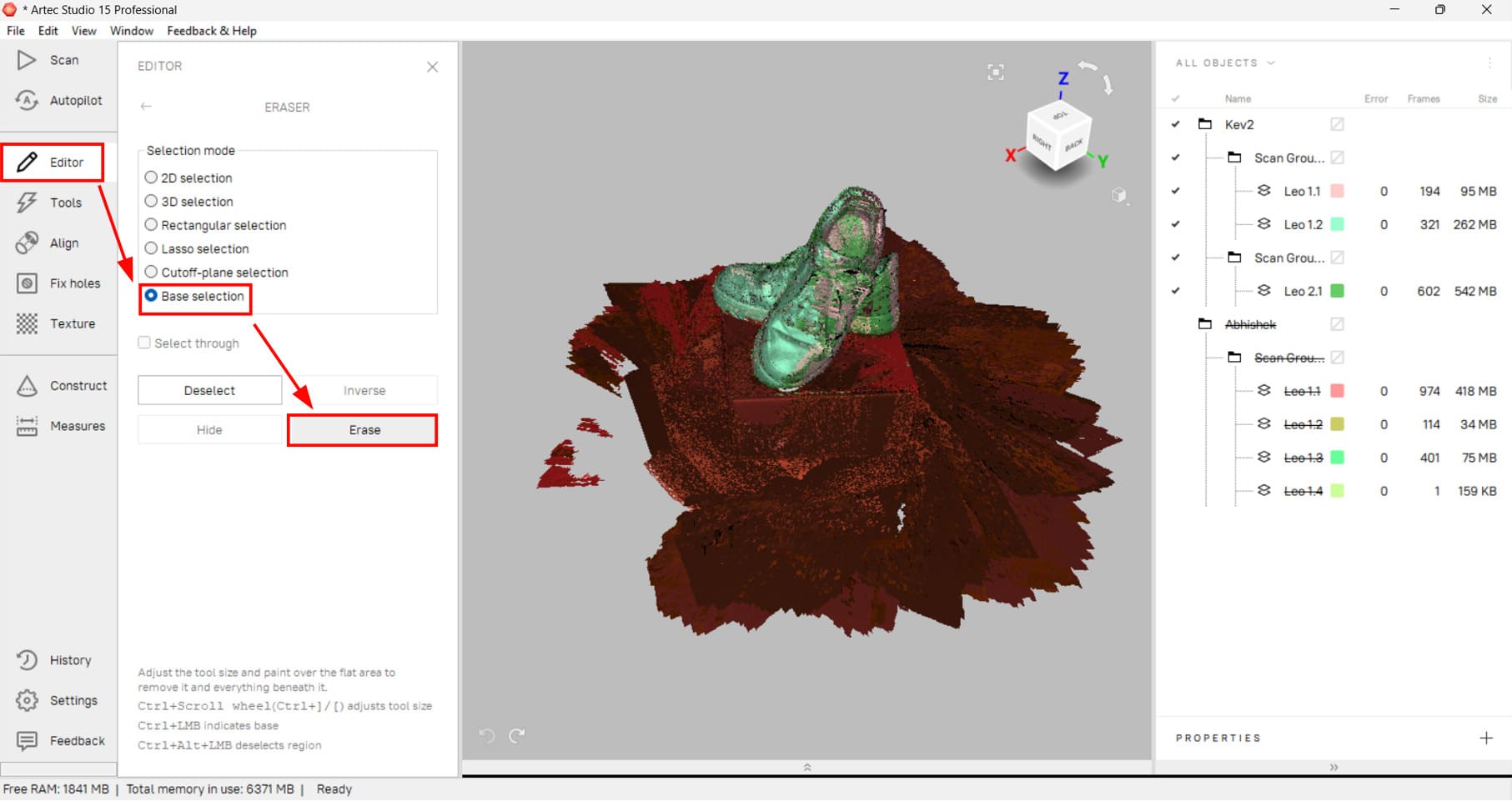
After clicking Erase, the entire red region was removed.
In the Tools tab, the scan was further cleaned.

Outlier removal was applied first.
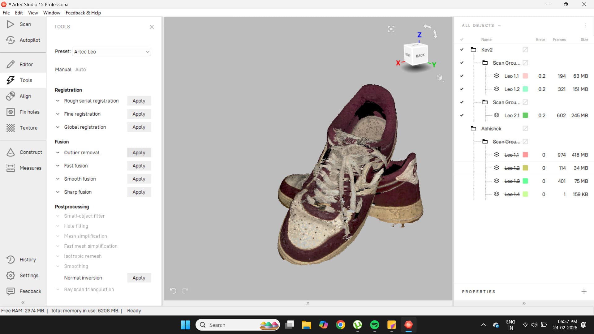
Some artifacts around the edges of the shoe were removed as a result.
Smooth fusion was applied next.
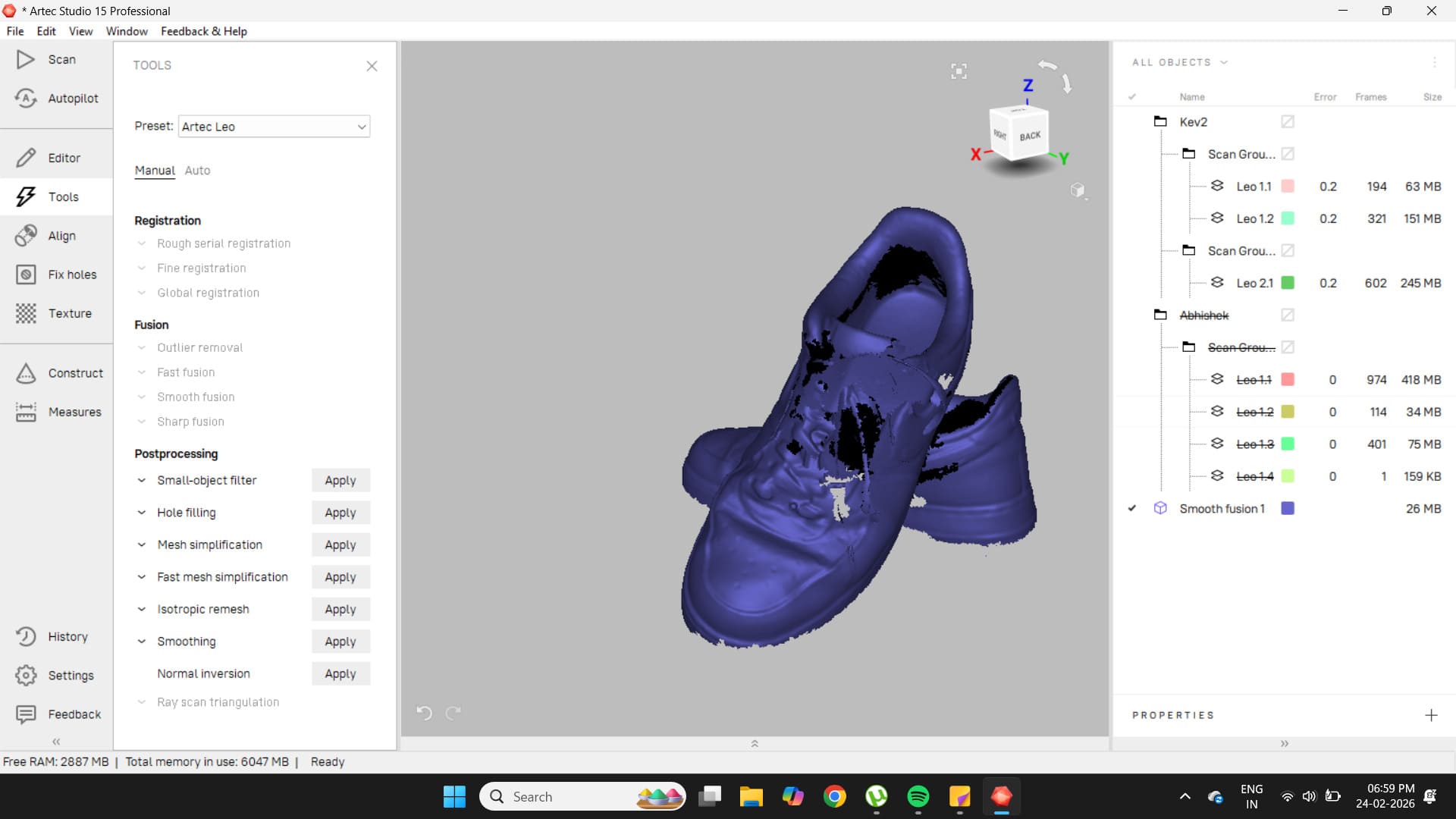
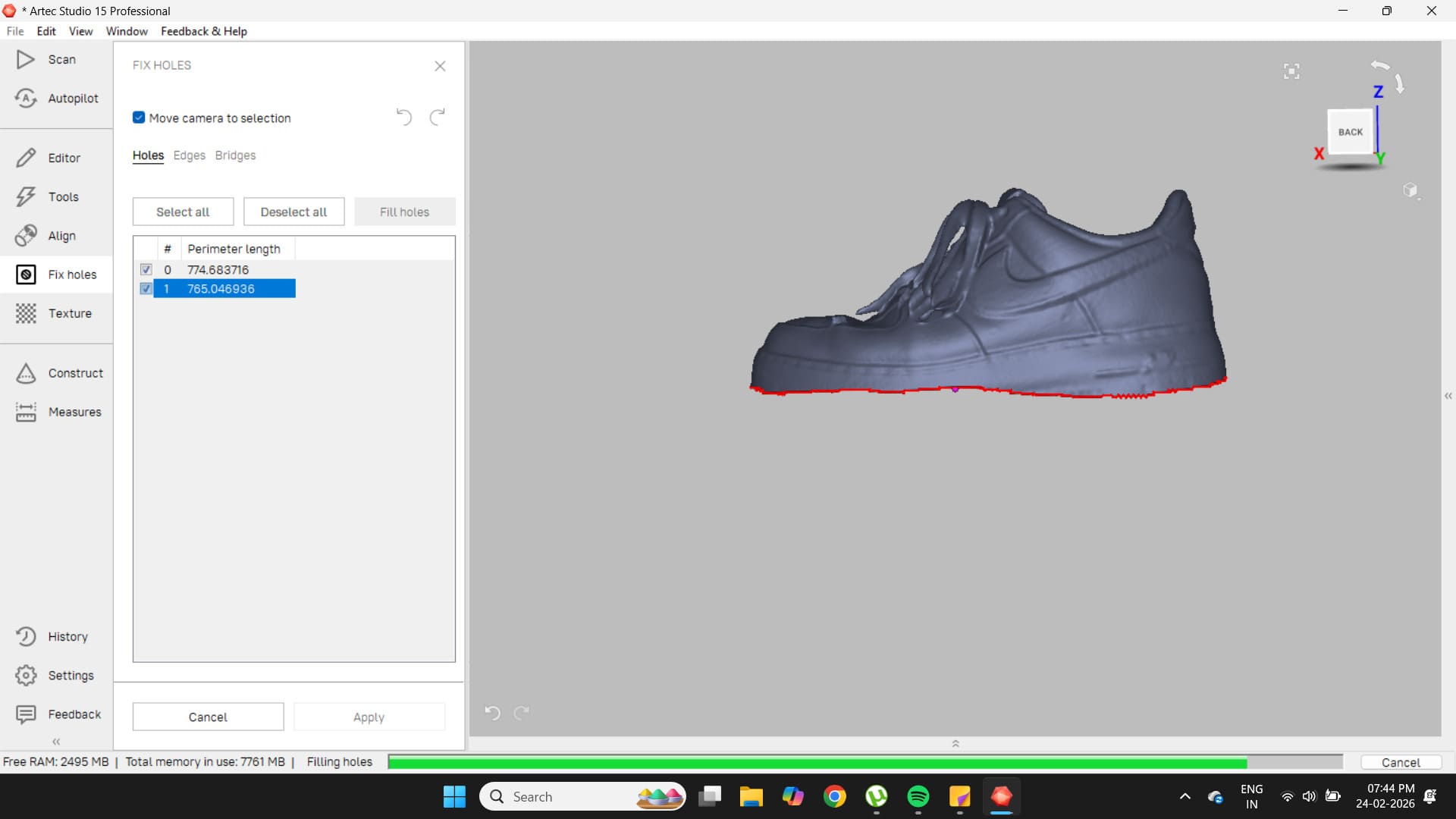
This exposed several large holes in the scan, which became more evident when the Fix Holes tool was opened.
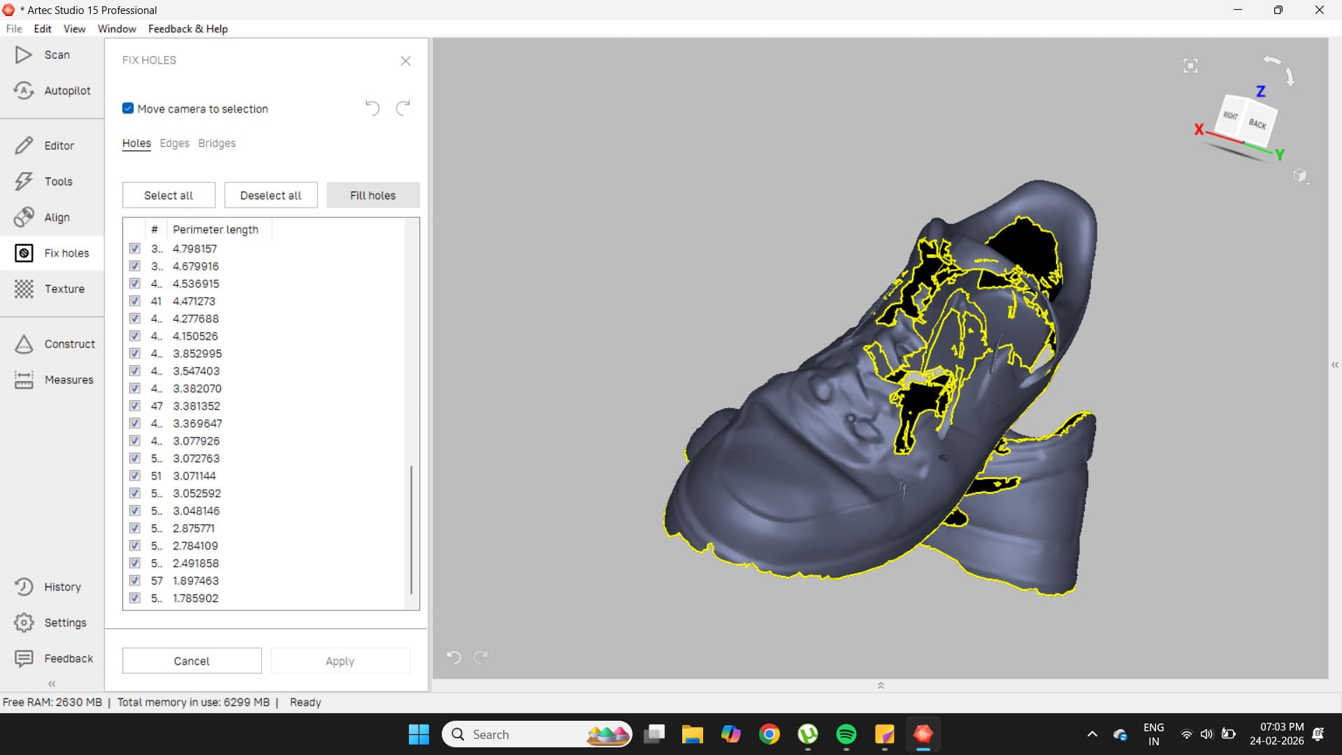
Filling these holes resulted in an imperfect model, so the decision was made to scan those areas again.
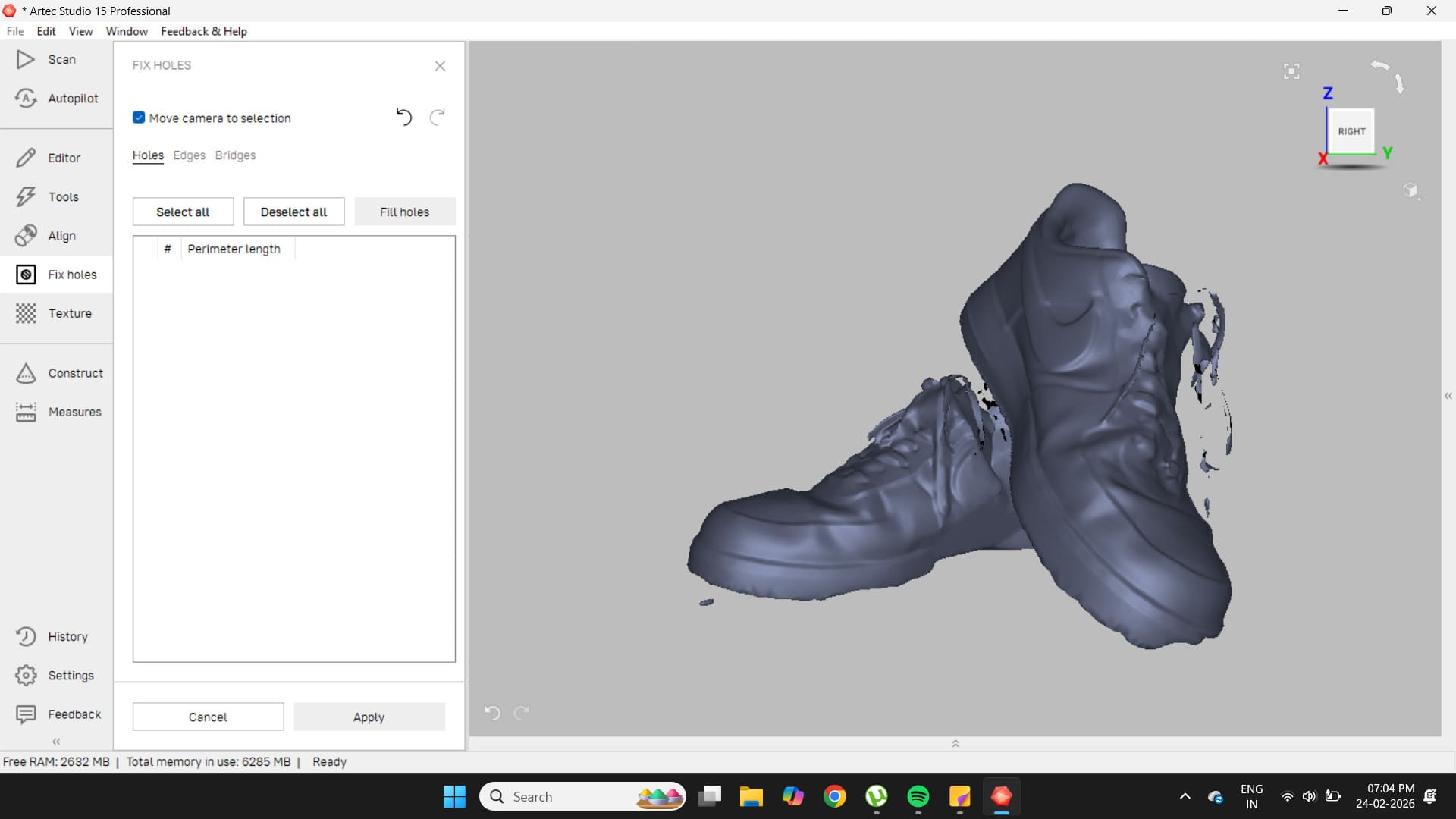
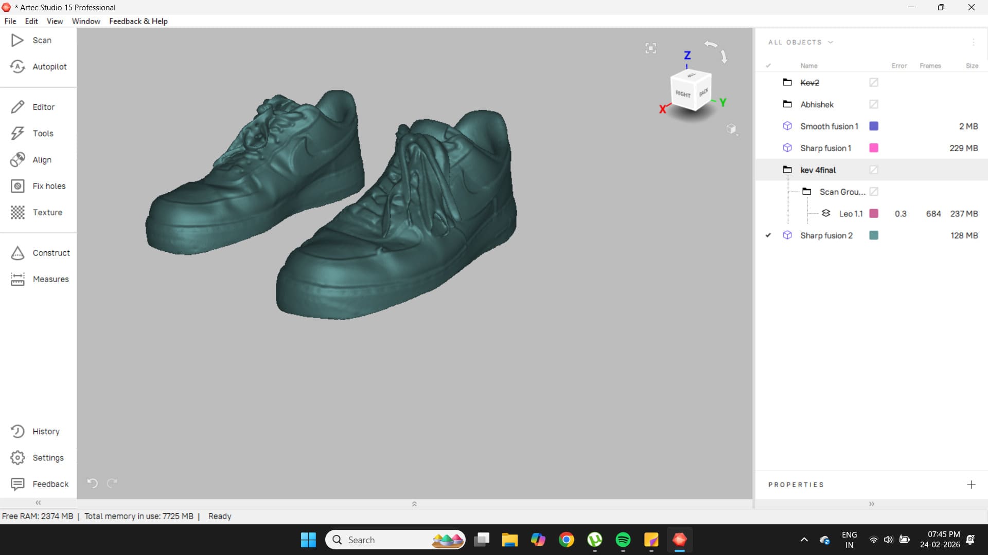
The new scan was of much higher quality.
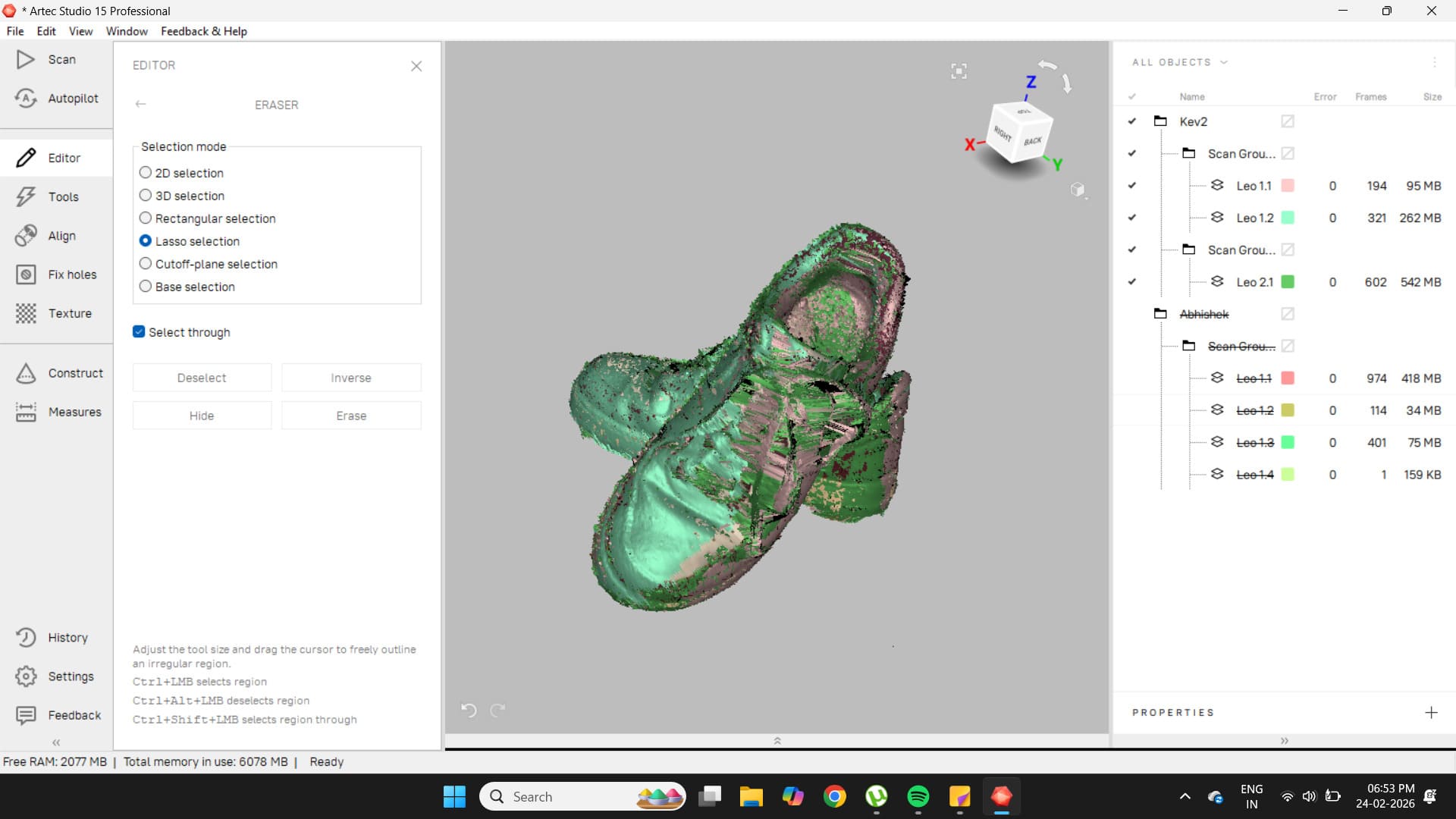
With this improved model, the Autopilot option was tested. The result was good, but the base of the shoe still contained some artifacts, which were removed using the lasso tool in the Editor.
These scans came out very well.
To export the file as an STL, go to File → Export Meshes.
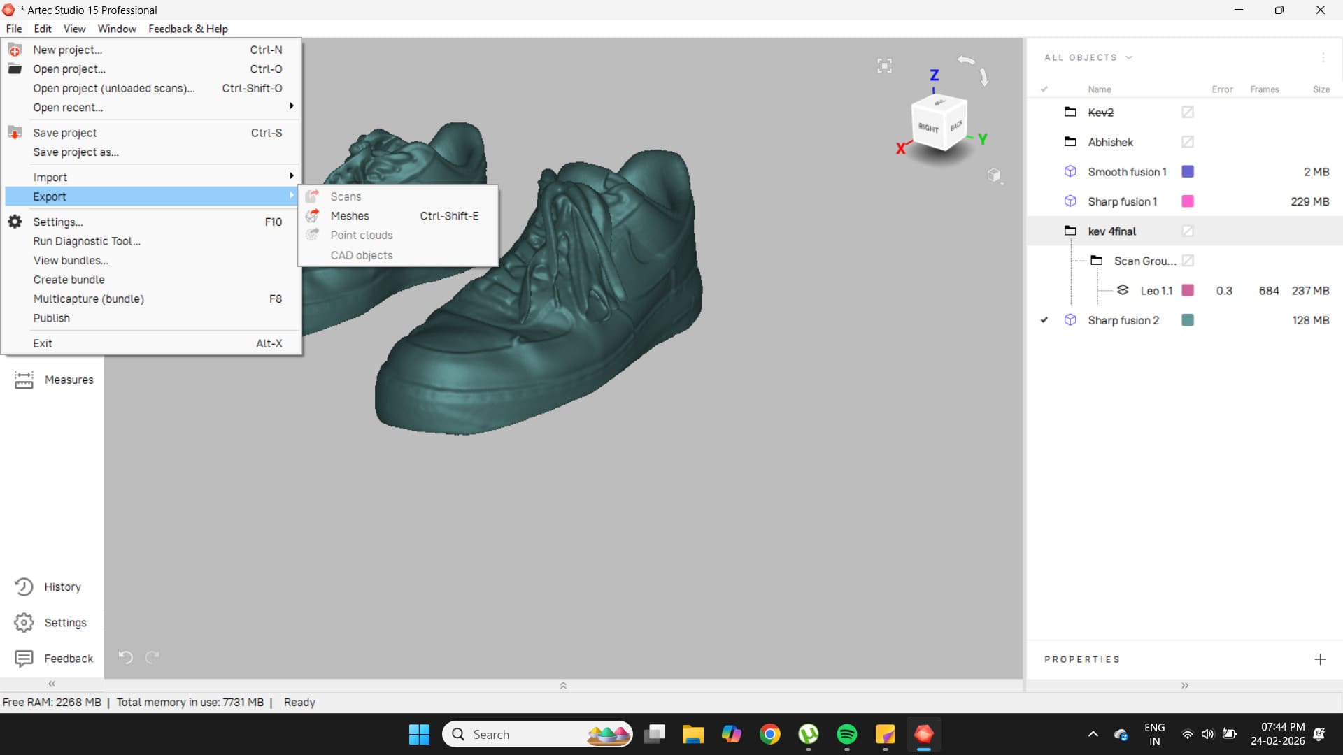
Here is the final scan.
Final Print
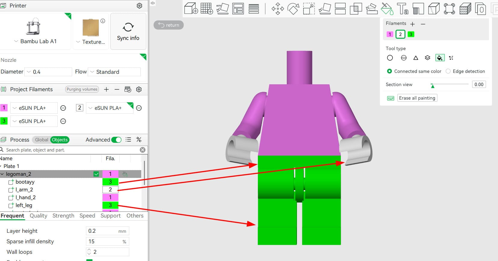
For the final print, I wanted to add colour. Using the paint tool, I set the appropriate colours for each part. Since each part was designed separately in Fusion, I was able to use the fill paint tool easily.
I then sent the file to the A1 with the correct filament types and colours selected and loaded onto the machine.
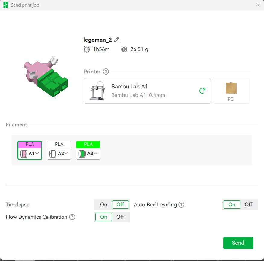
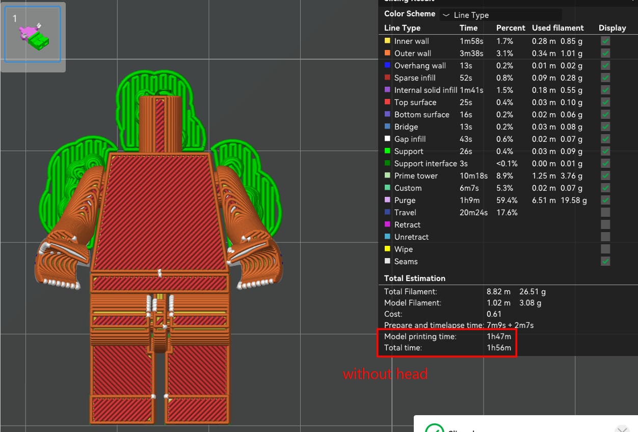
Here, I decided to print the head separately, as it is only one colour and would add another hour to the print. This image shows the slice with the head included; without it, the print time is slightly less than two hours.
Takes 1h45m without the head.
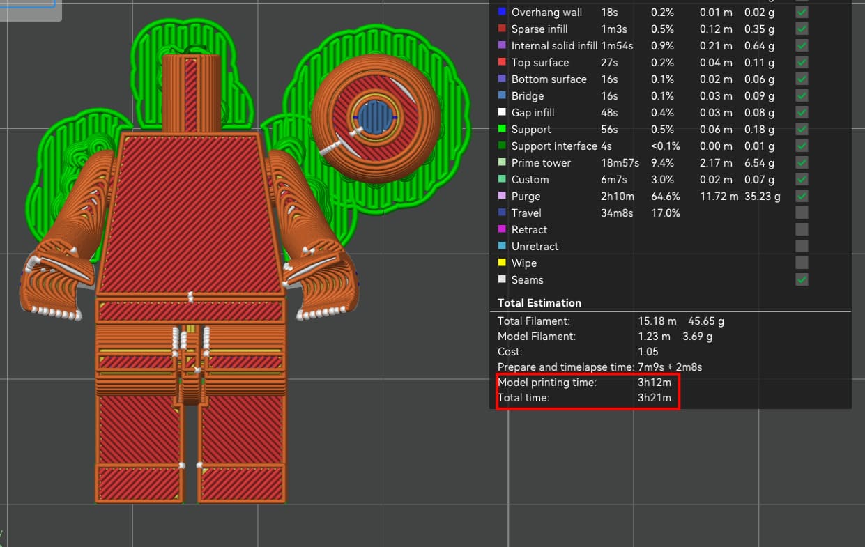
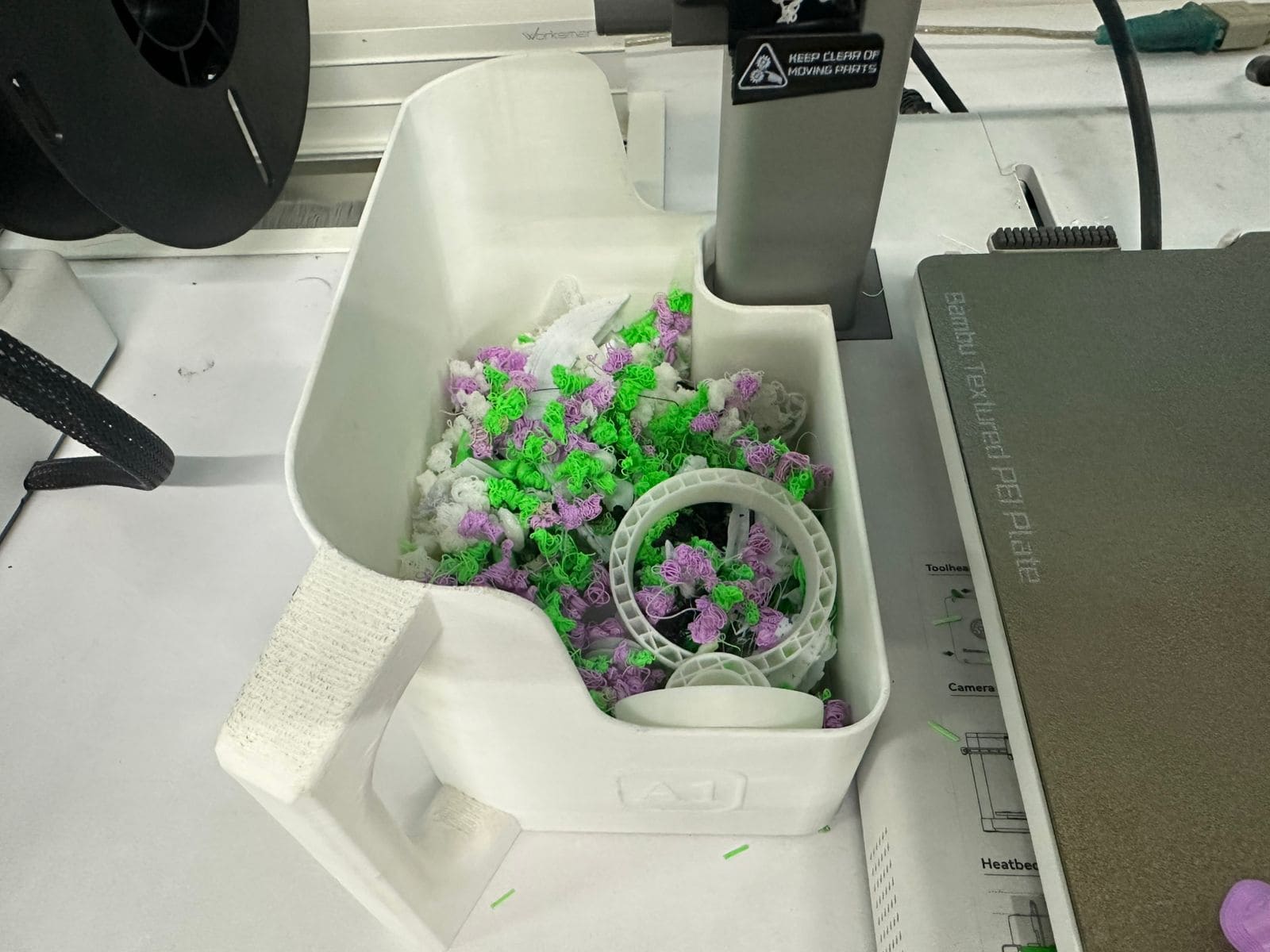
Since this was a multi-colour PLA print, it generated a significant amount of material waste (commonly referred to as “poop”) during filament changes.
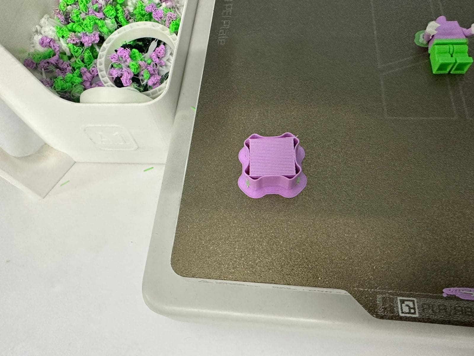
The print also created a structure known as a purge tower. This is a sacrificial tower used to maintain consistent extrusion pressure and to prevent colour mixing when switching between filaments.
Here is a timelapse of the entire print without the head.
Here is the final Man-Man with his new friend Superman.
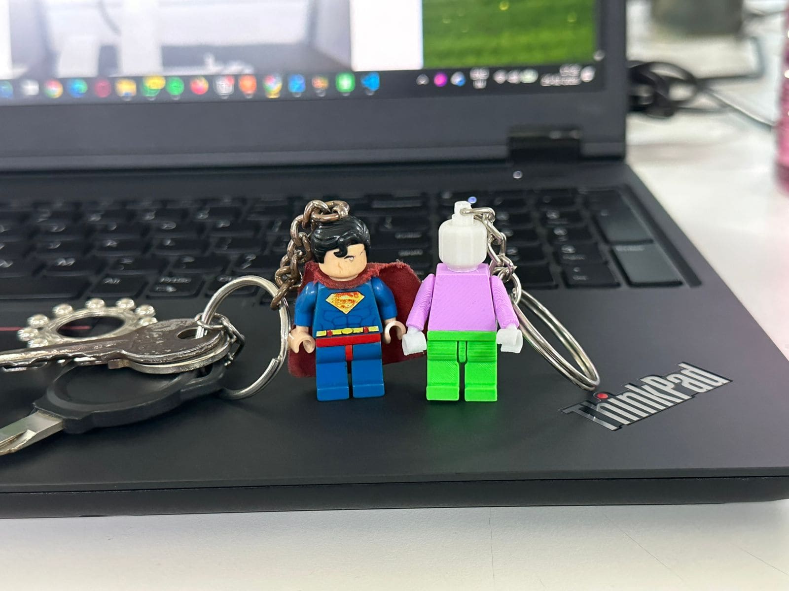
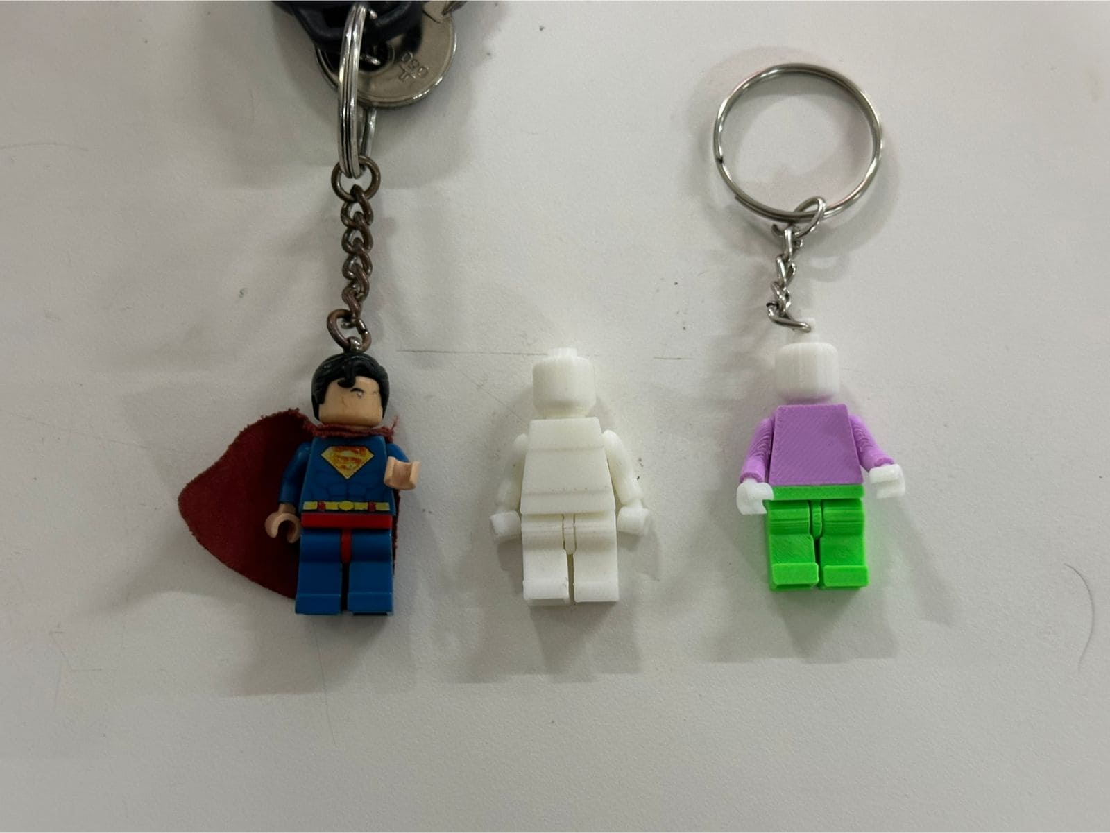
His print in place movable limbs.