4. Embedded Programming
- Group assignment
- demonstrate and compare the toolchains and development workflows for available embedded architectures
- Individual assignment
- browse through the data sheet for a microcontroller
- write and test a program for an embedded system using a microcontroller to interact (with input &/or output devices) and communicate (with wired or wireless connections)
- extra credit: assemble the system
- extra credit: try different languages &/or development environments
- Arduino UNO R4 WiFi provided the most beginner-friendly and highly abstracted workflow.
- ESP32-C6 required the most advanced setup and exposed low-level hardware interaction.
- ESP32-S3 provided a structured development environment with moderate complexity.
- ATtiny44/84 required manual compilation and flashing, providing a deeper understanding of embedded C and register-level programming.
- Dual-core Cortex-M0+ processors
- Programmable I/O (PIO) state machines
- DMA controller for high-speed data transfer
- Multiple communication interfaces (UART, SPI, I2C)
- Flexible GPIO multiplexing
Group Assignment
Explored various toolchains and development workflows for different embedded architectures. linked here
Toolchain Comparison
This comparison focuses specifically on toolchain setup and LED blink implementation across four different microcontroller platforms. The evaluation is based on practical experience configuring the development environment and implementing a simple GPIO blink program.
| Board | Development Environment | Programming Level | Build Process | Flashing Method | Blink Implementation | Observed Complexity |
|---|---|---|---|---|---|---|
| Arduino UNO R4 WiFi | Arduino IDE / Arduino Cloud | High-level C++ | Automatic compile and upload | USB (One-click) | digitalWrite() |
Very Easy |
| ESP32-C6 | VS Code + ESP-IDF | C / Assembly (RISC-V) | idf.py build |
idf.py flash |
Direct GPIO register control | High |
| ESP32-S3 DevKit | VS Code + PlatformIO | C++ (Arduino Framework) | PlatformIO build system | USB via PlatformIO | digitalWrite() / NeoPixel library |
Medium |
| ATtiny44/84 | Microchip Studio + AVR-GCC | Embedded C | Compile → Generate HEX | AVRDUDE + ISP Programmer | Direct PORT register manipulation | Medium (Low-level) |
Summary Observations
Conclusion
The comparison highlights how the development workflow and abstraction level vary significantly across different microcontroller platforms. Although all four boards successfully executed a basic LED blink program, the setup process, build system, flashing method, and programming approach differed considerably. This demonstrates how processor architecture and software ecosystem design have a direct impact on the embedded development experience.
Individual Assignment
Going through the datasheet for the RP2040.
The datasheet explains the naming nomenclature, internal structure of the chip, and the features available on-board.
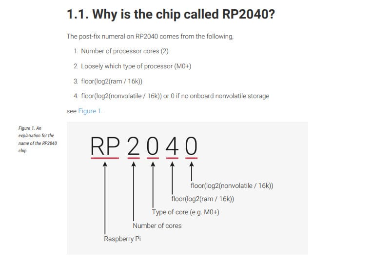
The RP2040 is a dual-core ARM Cortex-M0+ microcontroller designed for deterministic real-time performance. It includes on-chip SRAM, programmable I/O (PIO) blocks, multiple communication peripherals, and flexible clocking.
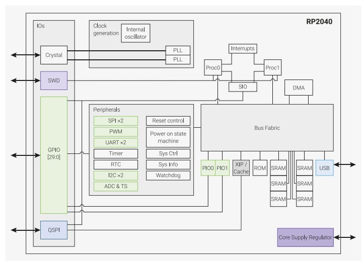
Key architectural points covered:
The pinout locations were also reviewed to understand GPIO placement, power pins, and special-function pins.

Seeed Studio XIAO RP2040 Development Board
This project uses the Seeed Studio XIAO RP2040, a compact and powerful development board based on the Raspberry Pi RP2040 microcontroller. Despite its small size (21 × 17.8 mm), it features a dual-core ARM Cortex-M0+ processor running at up to 133 MHz, 264 KB of SRAM, and 2 MB of onboard Flash memory. Its low power consumption and compact footprint make it well suited for embedded systems, wearable devices, and rapid prototyping.
The XIAO RP2040 provides 11 digital GPIO pins, 4 analog inputs, PWM support, and built-in I²C, SPI, and UART communication interfaces. It is fully compatible with the Arduino IDE, MicroPython, and CircuitPython, making it easy to develop and upload programs for a wide range of electronics projects.
XIAO RP2040 Pinout
.jpg)
Official Wiki: https://wiki.seeedstudio.com/XIAO-RP2040/
The onboard RGB LED is a common anode LED.
Common Anode Behavior:
LOW turns the LED color ON
HIGH turns it OFF
Red LEDs require very low voltage (around 2V). White and blue LEDs require higher voltage, so they will not turn on at lower voltages.
Depending on the input voltage range, different brightness levels can be observed.
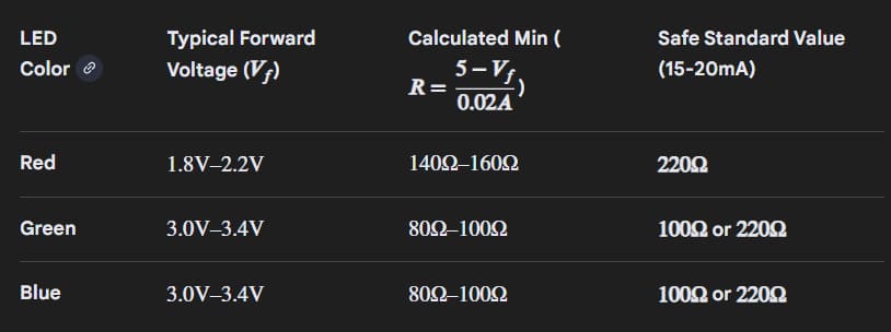
PROMPT: Required Resistance for different coloured LEDs
In digital logic circuits, pull-up and pull-down resistors are used to ensure a well-defined logical level on input pins.
Buttons are not ideal digital components. They do not switch cleanly between logical 0 and 1 and exhibit mechanical bouncing during transitions.
One way to handle this is through software debouncing using delays, or hardware methods such as capacitors.
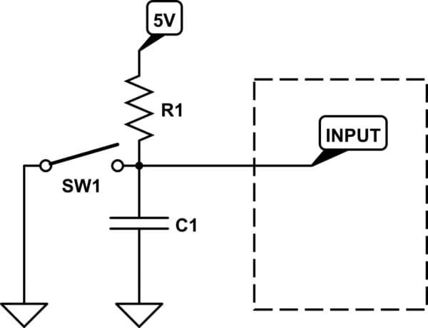
An RC filter is one method to reduce bouncing effects.
Arduino Software
Download Arduino IDE from the official website.
Arduino setup for RP2040 was done by following: https://wiki.seeedstudio.com/XIAO-RP2040/
Under File → Preferences, a JSON file was added to the Additional Board Manager URLs.
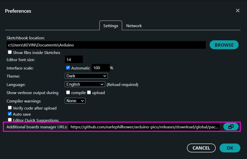
https://github.com/earlephilhower/arduino-pico/releases/download/global/package_rp2040_index.json
The RP2040 board package was then installed through the Boards Manager.
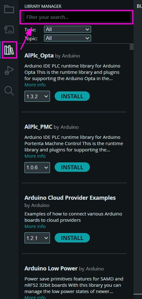
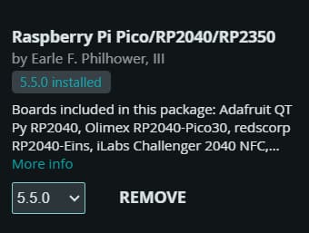
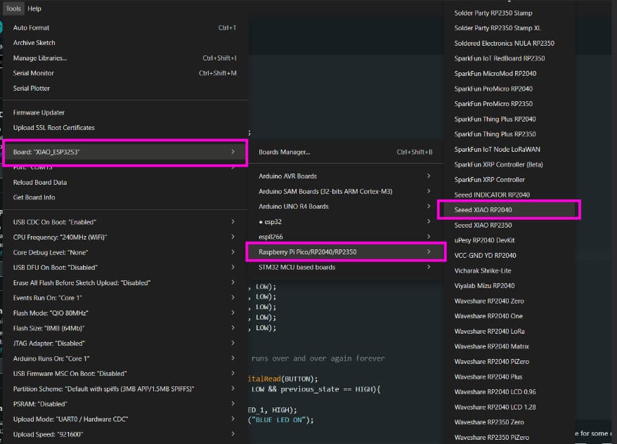
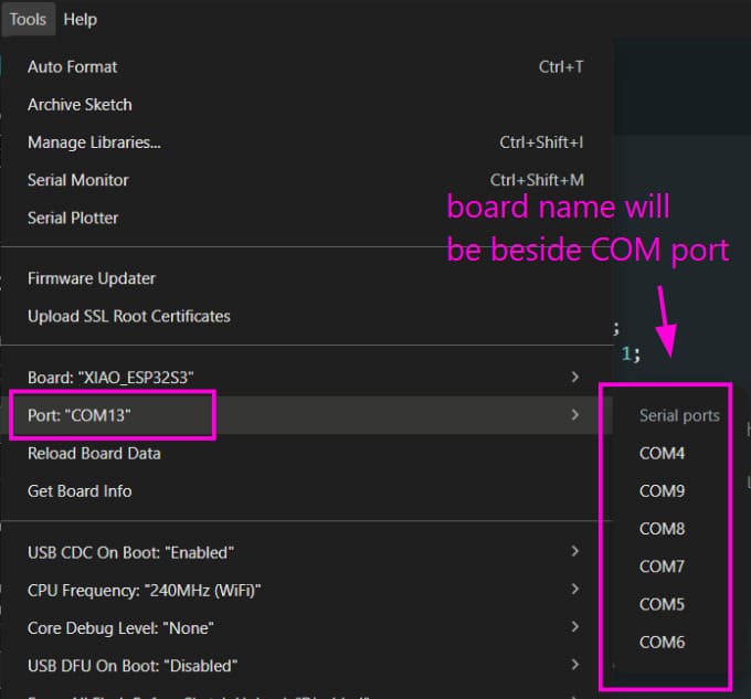
After installation, the correct board and port were selected from the Tools menu.
Code can now be written and uploaded to the board without issues.
For a simple test, we will try the onboard LED blink test. We use the example blink code for this.
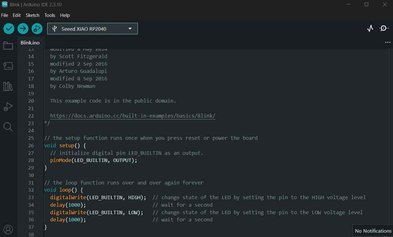
After uploading the code, the onboard LED should start blinking.
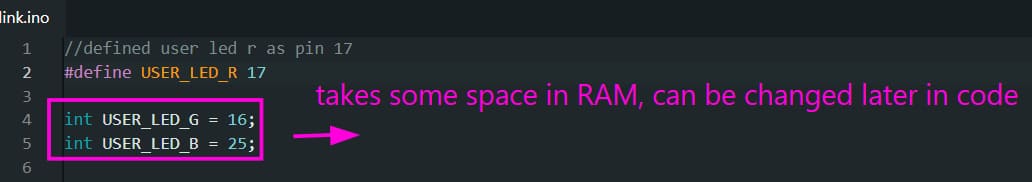
Now, I am going to write code for the LED array. Using #define sets a value globally, whereas a variable can be modified later during program execution.
The following defines the port numbers and pin directions:
pinMode(LED_1, OUTPUT);
pinMode(LED_2, OUTPUT);
pinMode(LED_3, OUTPUT);
pinMode(LED_4, OUTPUT);
pinMode(LED_5, OUTPUT);
pinMode(BUTTON, INPUT);
All LED pins are configured as outputs, and the button pin is configured as an input.
digitalWrite(LED_1, LOW);
This sets the voltage at the LED 1 pin to 0V.
button_state = digitalRead(BUTTON);
This reads the voltage level present at the button pin and stores it.
Firstly, make all the connections on a breadboard for testing the circuit. The circuit diagram is shown below.
.jpg)
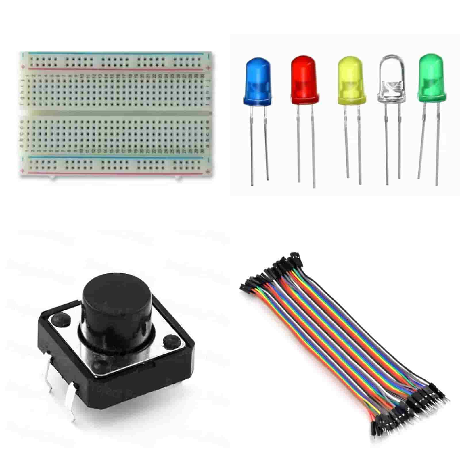
The various components used in the circuit are:
- Five LEDs (BLUE, RED, WHITE, YELLOW, GREEN)
- One push button
- Breadboard
- Jumper wires
The following program lights an array of LEDs sequentially using a button input and prints the active LED color to the serial monitor.
// ======================================================
// LED Control Using Push Button
// Each button press turns on the next LED in sequence.
// After all five LEDs are ON, the next press turns them
// all OFF and restarts the sequence.
// ======================================================

// ---------------- Pin Definitions ----------------
#define LED_5 D6
#define LED_4 D5
#define LED_3 D4
#define LED_2 D3
#define LED_1 D2
#define BUTTON D0

// ---------------- Global Variables ----------------
int button_state = 0;      // Stores the current button state
int previous_state = 1;    // Stores the previous button state (used for edge detection)
int a = 0;                 // Keeps track of which LED should turn on next

void setup() {
  // Initialize Serial Monitor
  Serial.begin(9600);

  // Configure LED pins as outputs
  pinMode(LED_1, OUTPUT);
  pinMode(LED_2, OUTPUT);
  pinMode(LED_3, OUTPUT);
  pinMode(LED_4, OUTPUT);
  pinMode(LED_5, OUTPUT);

  // Configure button pin as input
  pinMode(BUTTON, INPUT);

  // Ensure all LEDs are OFF at startup
  digitalWrite(LED_5, LOW);
  digitalWrite(LED_4, LOW);
  digitalWrite(LED_3, LOW);
  digitalWrite(LED_2, LOW);
  digitalWrite(LED_1, LOW);
}

void loop() {

  // Read the current state of the push button
  button_state = digitalRead(BUTTON);

  // Detect a button press (HIGH → LOW transition)
  // This prevents multiple triggers while the button is held down
  if (button_state == LOW && previous_state == HIGH) {

    // Turn on LEDs one by one
    if (a == 0) {
      digitalWrite(LED_1, HIGH);
      Serial.println("BLUE LED ON");
    }

    else if (a == 1) {
      digitalWrite(LED_2, HIGH);
      Serial.println("RED LED ON");
    }

    else if (a == 2) {
      digitalWrite(LED_3, HIGH);
      Serial.println("WHITE LED ON");
    }

    else if (a == 3) {
      digitalWrite(LED_4, HIGH);
      Serial.println("YELLOW LED ON");
    }

    else if (a == 4) {
      digitalWrite(LED_5, HIGH);
      Serial.println("GREEN LED ON");
    }

    // After all LEDs are ON, turn everything OFF
    else if (a >= 5) {
      delay(200);  // Small debounce delay

      digitalWrite(LED_1, LOW);
      digitalWrite(LED_2, LOW);
      digitalWrite(LED_3, LOW);
      digitalWrite(LED_4, LOW);
      digitalWrite(LED_5, LOW);

      Serial.println("ALL LED OFF");

      // Reset counter so the sequence starts again
      a = -1;
    }

    // Move to the next LED in the sequence
    a++;

    // Simple debounce delay
    delay(200);
  }

  // Save the current button state for the next loop iteration
  previous_state = button_state;
}
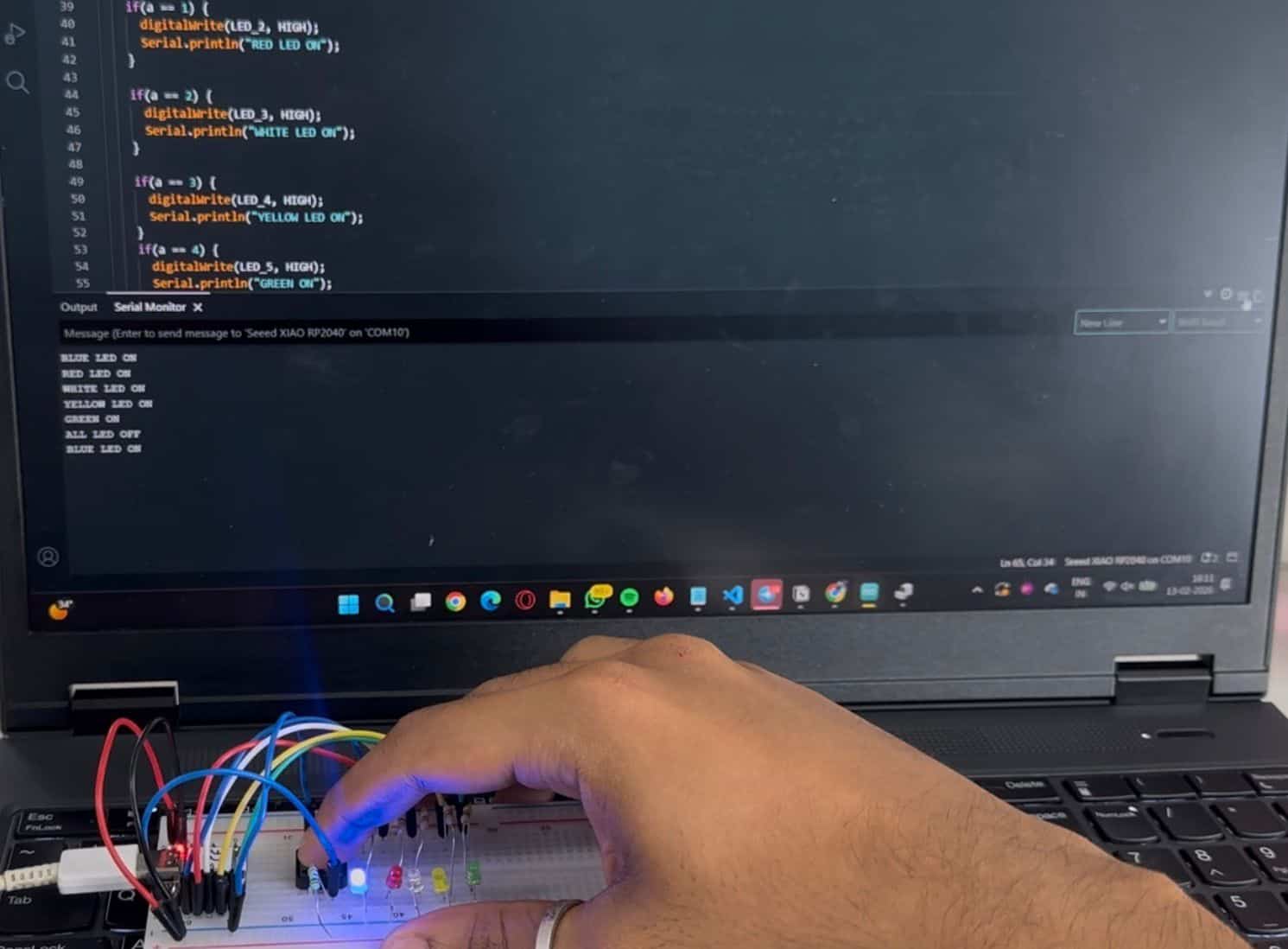
The Serial Monitor is a built-in tool in the Arduino IDE that allows the microcontroller to send and receive text over a serial communication link. It is mainly used for debugging, printing sensor values, and verifying that a program is running correctly.
After uploading the program, I opened the Serial Monitor by selecting Tools → Serial Monitor from the Arduino IDE menu (or by clicking the Serial Monitor icon in the top-right corner).
.jpg)
The baud rate is the communication speed between the computer and the microcontroller, measured in bits per second (bps). The baud rate set in the code must match the baud rate selected in the Serial Monitor for the data to be displayed correctly.
For this assignment, I used a baud rate of 9600 bps by initializing serial communication with:
Serial.begin(9600);On clicking the button it displays on the serial monitor which colour LED is turned on.
Bouncing is handled using a delay and a previous-state check to avoid multiple detections from a single button press.
Micropython Software
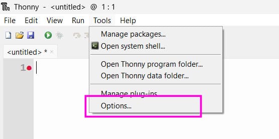
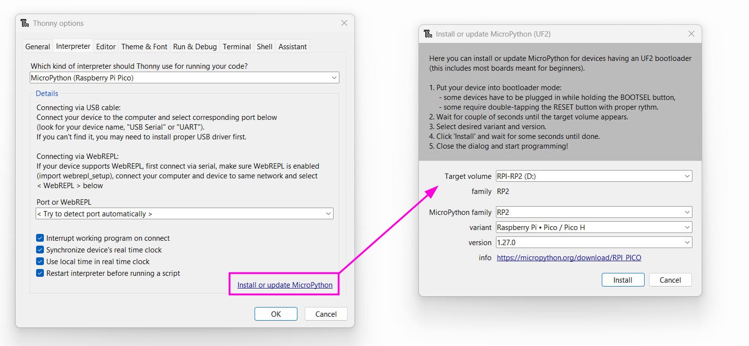
MicroPython was set up using Thonny. I followed this tutorial to get through the setup process.
Under Tools → Options → Interpreter, MicroPython for Raspberry Pi Pico was selected.
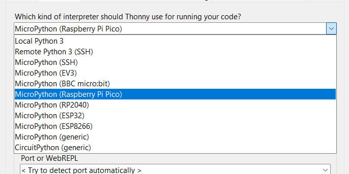
The “Install or update MicroPython” option was used, and the connected RP2040 board was detected automatically.
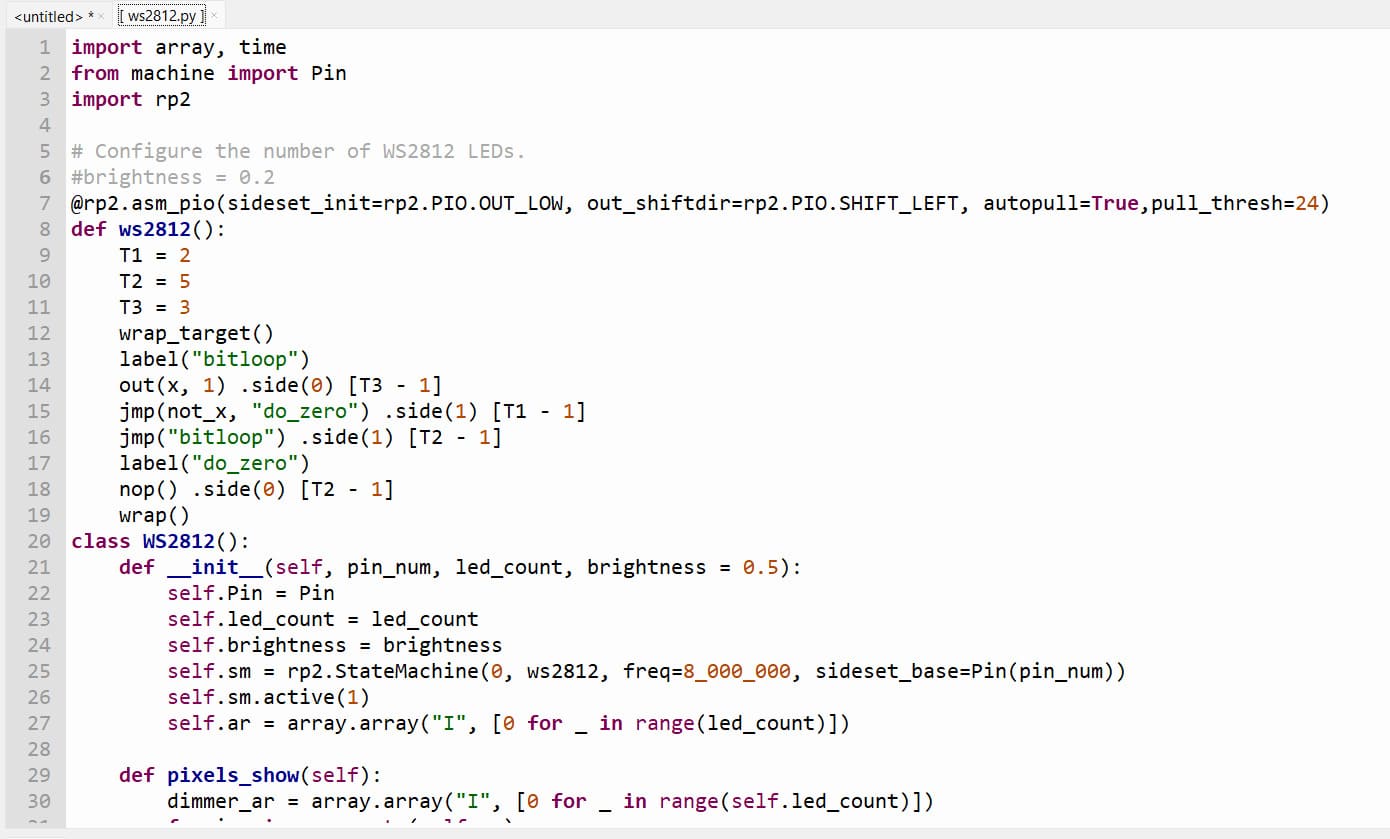
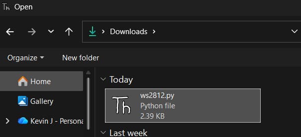
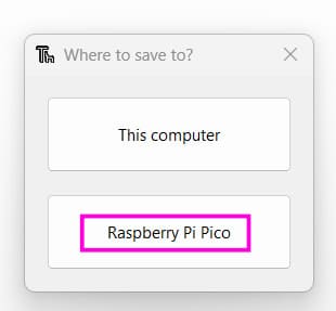
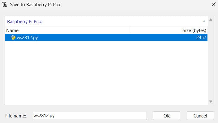
For RGB LED control, a WS2812 library was downloaded and saved directly onto the RP2040 board.
# ======================================================
# WS2812 RGB LED Colour Cycling
# Cycles a single WS2812 (NeoPixel) LED through a series
# of predefined colours with a short delay.
# ======================================================

from ws2812 import WS2812
import utime
import machine

# ---------------- Power Configuration ----------------
# Enable power to the onboard RGB LED
power = machine.Pin(11, machine.Pin.OUT)
power.value(1)

# ---------------- Colour Definitions ----------------
# RGB values are in the format (Red, Green, Blue)

BLACK  = (0, 0, 0)         # LED Off
RED    = (255, 0, 0)
YELLOW = (255, 150, 0)
GREEN  = (0, 255, 0)
CYAN   = (0, 255, 255)
BLUE   = (0, 0, 255)
PURPLE = (180, 0, 255)
WHITE  = (255, 255, 255)

# Store all colours in a tuple for easy iteration
COLORS = (
    BLACK,
    RED,
    YELLOW,
    GREEN,
    CYAN,
    BLUE,
    PURPLE,
    WHITE
)

# ---------------- LED Initialization ----------------
# WS2812(data_pin, number_of_leds)
# Data pin = GPIO12
# Number of LEDs = 1
led = WS2812(12, 1)

# ---------------- Main Loop ----------------
while True:

    # Print a message to the serial console
    print("RGB Colours")

    # Cycle through each predefined colour
    for color in COLORS:

        # Set the LED to the current colour
        led.pixels_fill(color)

        # Update the LED with the new colour
        led.pixels_show()

        # Keep the colour displayed for 0.2 seconds
        utime.sleep(0.2)
All required files are stored directly on the microcontroller, and the script can be run directly from Thonny.
Seeed Studio XIAO ESP32 S3 Sense
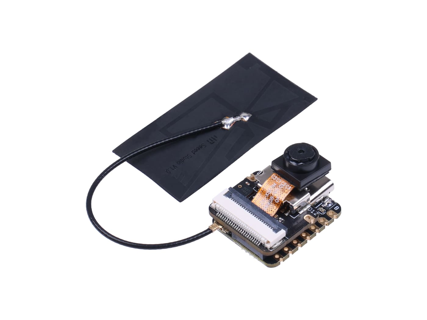
.jpg)
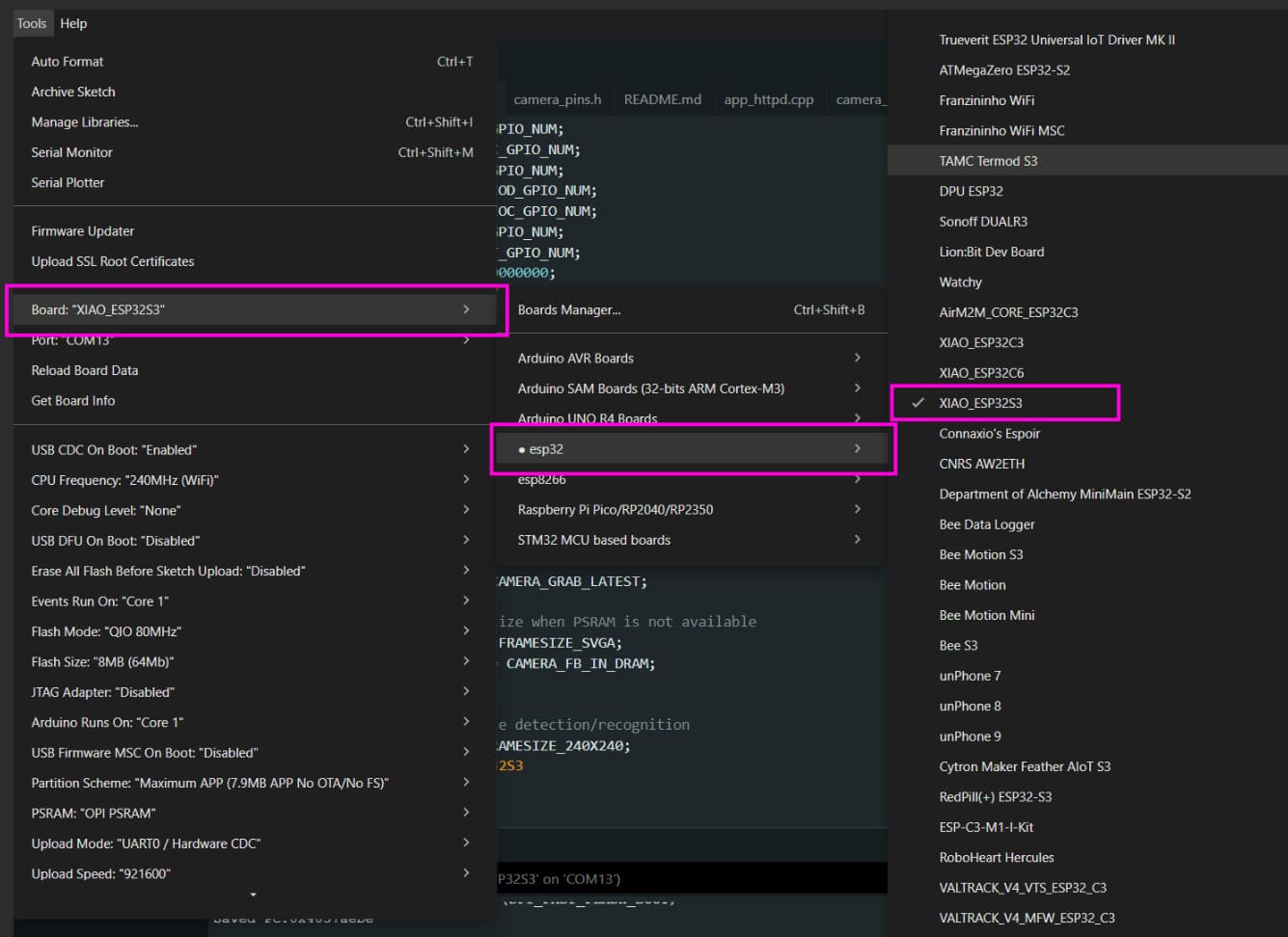
To use the Seeed Studio XIAO ESP32 S3 Sense, the ESP32 board support must first be added to Arduino.
The board URL is added under File → Preferences → Additional Board Manager URLs.
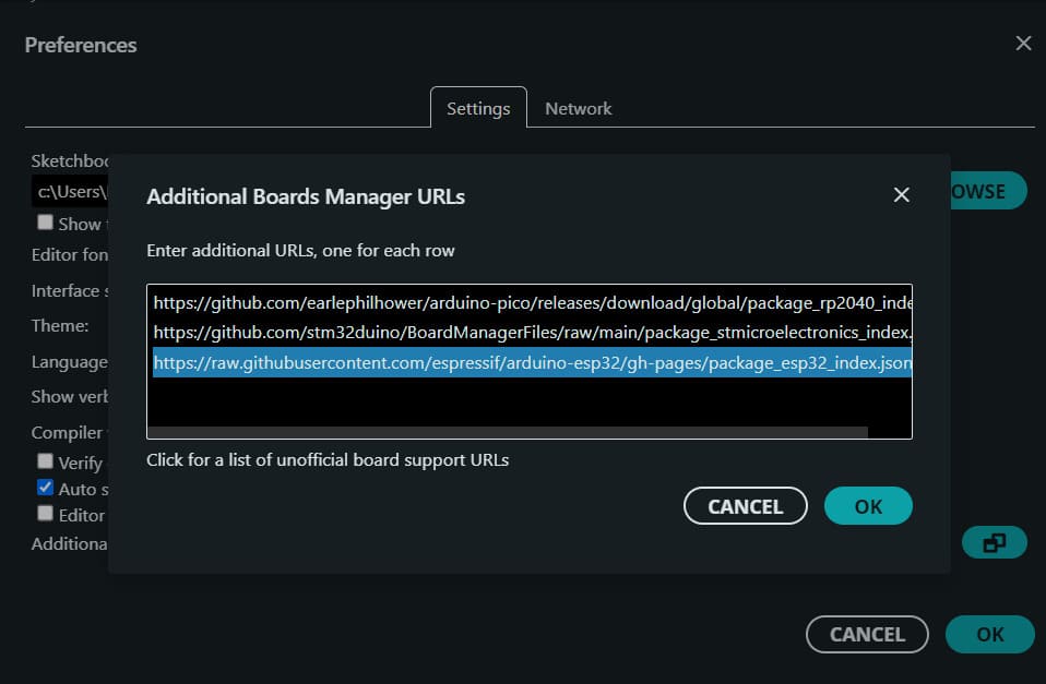
https://raw.githubusercontent.com/espressif/arduino-esp32/gh-pages/package_esp32_index.json
After adding the URL, the ESP32 packages are installed using the Boards Manager.
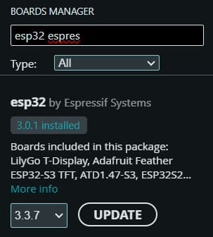
Once installed, the correct ESP32-S3 Sense device and serial port can be selected.
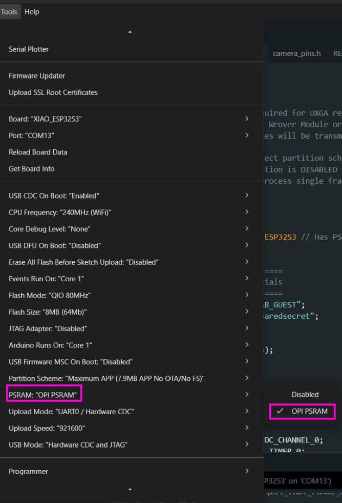
The XIAO ESP32-S3 Sense has external PSRAM, which is required for camera streaming and high-resolution frame buffers.
PSRAM must be enabled from the Tools dropdown.
Setting up Photo Capture over HTTPS
WiFi credentials and camera parameters:
#define WIFI_SSID     "FAB_LAB_GUEST"
#define WIFI_PASS     "sharedsecret"
#define FRAME_SIZE    FRAMESIZE_UXGA
#define JPEG_QUALITY  8
FRAMESIZE_UXGA is the OV2640 internal resolution code for 1600 × 1200.
JPEG_QUALITY controls internal sensor compression.
Lower values mean higher quality and larger image size.
Camera pin definitions. These represent the actual wire connections between the ESP32-S3 and the OV2640 sensor on the expansion board.
#define PWDN_GPIO_NUM   -1
#define RESET_GPIO_NUM  -1
#define XCLK_GPIO_NUM   10
#define SIOD_GPIO_NUM   40
#define SIOC_GPIO_NUM   39
#define Y9_GPIO_NUM     48
#define Y8_GPIO_NUM     11
#define Y7_GPIO_NUM     12
#define Y6_GPIO_NUM     14
#define Y5_GPIO_NUM     16
#define Y4_GPIO_NUM     18
#define Y3_GPIO_NUM     17
#define Y2_GPIO_NUM     15
#define VSYNC_GPIO_NUM  38
#define HREF_GPIO_NUM   47
#define PCLK_GPIO_NUM   13
#define LED_GPIO_NUM    21
httpd_handle_t server = NULL;
Global variable holding a reference to the HTTP server instance.
static esp_err_t captureHandler(httpd_req_t* req) {
Callback function.
The HTTP server automatically calls this when a browser or script sends GET /capture.
camera_fb_t* fb = esp_camera_fb_get();
Returns a pointer to the most recent frame buffer stored in DMA-accessible memory.
if (!fb) {
    httpd_resp_send_500(req);
    return ESP_FAIL;
}
If the frame buffer is null, the handler fails and returns an HTTP 500 error.
httpd_resp_set_type(req, "image/jpeg");
httpd_resp_set_hdr(req, "Access-Control-Allow-Origin", "*");
httpd_resp_set_hdr(req, "Cache-Control", "no-cache");
Sets the response type to JPEG so browsers display the image correctly.
Access-Control-Allow-Origin allows any webpage to fetch the image.
no-cache forces every request to return a fresh frame.
esp_err_t res = httpd_resp_send(req, (const char*)fb->buf, fb->len);
esp_camera_fb_return(fb);
httpd_resp_send sends the JPEG bytes over the network.
esp_camera_fb_return releases the buffer so the camera can write the next frame.
camera_config_t config;
config.ledc_channel = LEDC_CHANNEL_0;
config.ledc_timer   = LEDC_TIMER_0;
camera_config_t is a struct holding all camera initialization parameters.
The LEDC timer and channel generate the clock signal sent to the camera.
config.pin_d0 = Y2_GPIO_NUM;
config.pin_d1 = Y3_GPIO_NUM;
config.pin_d2 = Y4_GPIO_NUM;
config.pin_d3 = Y5_GPIO_NUM;
config.pin_d4 = Y6_GPIO_NUM;
config.pin_d5 = Y7_GPIO_NUM;
config.pin_d6 = Y8_GPIO_NUM;
config.pin_d7 = Y9_GPIO_NUM;
config.pin_xclk = XCLK_GPIO_NUM;
config.pin_pclk = PCLK_GPIO_NUM;
config.pin_vsync = VSYNC_GPIO_NUM;
config.pin_href = HREF_GPIO_NUM;
config.pin_sccb_sda = SIOD_GPIO_NUM;
config.pin_sccb_scl = SIOC_GPIO_NUM;
The camera communicates using two buses:
- Parallel data bus (D0–D7) for raw pixel data
- SCCB bus (SDA + SCL), a modified I2C protocol used to configure the sensor
Timing signals:
config.pin_vsync = VSYNC_GPIO_NUM;   // pulses once per frame
config.pin_href  = HREF_GPIO_NUM;    // pulses once per row
config.pin_pclk  = PCLK_GPIO_NUM;    // pulses once per pixel
config.pin_xclk  = XCLK_GPIO_NUM;    // master clock to sensor
config.fb_location = CAMERA_FB_IN_PSRAM;
config.fb_count    = 2;
config.grab_mode   = CAMERA_GRAB_LATEST;
Frame buffers are allocated in the 8 MB external PSRAM instead of internal RAM.
Two buffers enable double buffering: one frame is captured while the other is being read.
CAMERA_GRAB_LATEST ensures the most recent frame is always returned.
esp_camera_init(&config);
This initializes the camera clock, SCCB bus, configures the OV2640 registers, allocates buffers, and starts DMA transfers.
sensor_t* s = esp_camera_sensor_get();
s->set_framesize(s,   FRAME_SIZE);
s->set_quality(s,     JPEG_QUALITY);
s->set_contrast(s,    2);
s->set_brightness(s,  1);
s->set_saturation(s, -2);
s->set_sharpness(s,   2);
s->set_whitebal(s,    1);
s->set_exposure_ctrl(s, 1);
s->set_gain_ctrl(s,   1);
s->set_lenc(s,        1);
s->set_bpc(s,         1);
s->set_wpc(s,         1);
sensor_t is a struct of function pointers forming an API for the OV2640.
Each set_* call writes to a specific internal sensor register using SCCB (I2C).
WiFi.begin(WIFI_SSID, WIFI_PASS);
WiFi.setSleep(false);

while (WiFi.status() != WL_CONNECTED) {
    delay(500);
    Serial.print(".");
}
WiFi.setSleep(false) disables modem power-saving mode.
This is necessary for stable streaming and low-latency transfers.
httpd_config_t srv_cfg = HTTPD_DEFAULT_CONFIG();
httpd_start(&server, &srv_cfg);

httpd_uri_t cap_uri = {
    .uri     = "/capture",
    .method  = HTTP_GET,
    .handler = captureHandler,
    .user_ctx = NULL
};

httpd_register_uri_handler(server, &cap_uri);
HTTPD_DEFAULT_CONFIG fills the configuration with default values such as port 80 and stack size.
httpd_start launches the HTTP server as a FreeRTOS task on the second core.
The httpd_uri_t structure maps a GET request to /capture directly to the captureHandler function.
Output
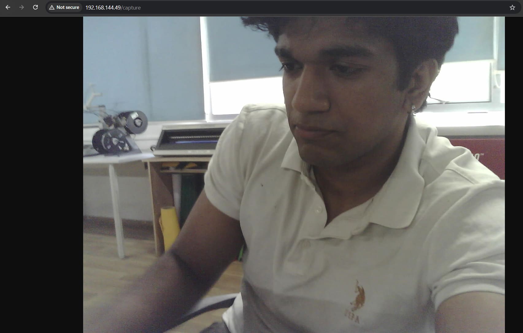
Full Code
Setup guide and original reference: Xiao ESP32S3 Camera Usage Guide
#include "esp_camera.h"
#include
#include "esp_http_server.h"
// ── Your credentials ──────────────────────────────────────────────
#define WIFI_SSID "FAB_LAB_GUEST"
#define WIFI_PASS "sharedsecret"
// ── Fixed camera settings ─────────────────────────────────────────
#define FRAME_SIZE FRAMESIZE_UXGA // 1600×1200 — change to FRAMESIZE_SVGA for 800×600
#define JPEG_QUALITY 8 // 0=best, 63=worst. 8 is very high quality.
// ── XIAO ESP32-S3 Sense pins (do not change) ─────────────────────
#define PWDN_GPIO_NUM -1
#define RESET_GPIO_NUM -1
#define XCLK_GPIO_NUM 10
#define SIOD_GPIO_NUM 40
#define SIOC_GPIO_NUM 39
#define Y9_GPIO_NUM 48
#define Y8_GPIO_NUM 11
#define Y7_GPIO_NUM 12
#define Y6_GPIO_NUM 14
#define Y5_GPIO_NUM 16
#define Y4_GPIO_NUM 18
#define Y3_GPIO_NUM 17
#define Y2_GPIO_NUM 15
#define VSYNC_GPIO_NUM 38
#define HREF_GPIO_NUM 47
#define PCLK_GPIO_NUM 13
#define LED_GPIO_NUM 21
httpd_handle_t server = NULL;
// ── /capture handler — returns a single JPEG ─────────────────────
static esp_err_t captureHandler(httpd_req_t* req) {
camera_fb_t* fb = esp_camera_fb_get();
if (!fb) {
httpd_resp_send_500(req);
return ESP_FAIL;
}
httpd_resp_set_type(req, "image/jpeg");
httpd_resp_set_hdr(req, "Access-Control-Allow-Origin", "*");
httpd_resp_set_hdr(req, "Cache-Control", "no-cache");
esp_err_t res = httpd_resp_send(req, (const char*)fb->buf, fb->len);
esp_camera_fb_return(fb);
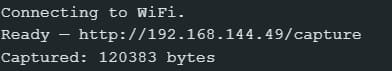
Serial.printf("Captured: %u bytes\n", fb->len);
return res;
}
void setup() {
Serial.begin(115200);
pinMode(LED_GPIO_NUM, OUTPUT);
digitalWrite(LED_GPIO_NUM, HIGH); // off (active LOW)
// ── Camera config ───────────────────────────────────────────────
camera_config_t config;
config.ledc_channel = LEDC_CHANNEL_0;
config.ledc_timer = LEDC_TIMER_0;
config.pin_d0 = Y2_GPIO_NUM;
config.pin_d1 = Y3_GPIO_NUM;
config.pin_d2 = Y4_GPIO_NUM;
config.pin_d3 = Y5_GPIO_NUM;
config.pin_d4 = Y6_GPIO_NUM;
config.pin_d5 = Y7_GPIO_NUM;
config.pin_d6 = Y8_GPIO_NUM;
config.pin_d7 = Y9_GPIO_NUM;
config.pin_xclk = XCLK_GPIO_NUM;
config.pin_pclk = PCLK_GPIO_NUM;
config.pin_vsync = VSYNC_GPIO_NUM;
config.pin_href = HREF_GPIO_NUM;
config.pin_sccb_sda = SIOD_GPIO_NUM;
config.pin_sccb_scl = SIOC_GPIO_NUM;
config.pin_pwdn = PWDN_GPIO_NUM;
config.pin_reset = RESET_GPIO_NUM;
config.xclk_freq_hz = 20000000;
config.pixel_format = PIXFORMAT_JPEG;
config.frame_size = FRAME_SIZE;
config.jpeg_quality = JPEG_QUALITY;
config.fb_count = 2;
config.fb_location = CAMERA_FB_IN_PSRAM;
config.grab_mode = CAMERA_GRAB_LATEST;
if (esp_camera_init(&config) != ESP_OK) {
Serial.println("Camera init failed — check expansion board connection");
while (true) {
digitalWrite(LED_GPIO_NUM, LOW); delay(100);
digitalWrite(LED_GPIO_NUM, HIGH); delay(100);
}
}
sensor_t* s = esp_camera_sensor_get();
s->set_framesize(s, FRAME_SIZE);
s->set_quality(s, JPEG_QUALITY);
s->set_contrast(s, 2);
s->set_brightness(s, 1);
s->set_saturation(s, -2);
s->set_sharpness(s, 2);
s->set_whitebal(s, 1);
s->set_exposure_ctrl(s, 1);
s->set_gain_ctrl(s, 1);
s->set_lenc(s, 1);
s->set_bpc(s, 1);
s->set_wpc(s, 1);
WiFi.begin(WIFI_SSID, WIFI_PASS);
WiFi.setSleep(false);
while (WiFi.status() != WL_CONNECTED) {
delay(500);
}
httpd_config_t srv_cfg = HTTPD_DEFAULT_CONFIG();
httpd_start(&server, &srv_cfg);
httpd_uri_t cap_uri = {
.uri = "/capture",
.method = HTTP_GET,
.handler = captureHandler,
.user_ctx = NULL
};
httpd_register_uri_handler(server, &cap_uri);
}
void loop() {
delay(10000);
}
Conclusions
Working with both languages highlighted the trade-off between Arduino C's low-level control and MicroPython's ease of programming and flexibility.
This link contains all the project files.