3. Computer-Controlled Cutting
- Group assignment
- Do your lab’s safety training
- Do your lab’s safety trainingCharacterize your lasercutter’s focus, power, speed, rate, kerf, joint clearance and types.
- Document your work to the group work page and reflect on your individual page what you learned.
- Individual assignment
- Design, lasercut, and document a parametric construction kit, accounting for the lasercutter kerf.
- Cut something on the vinyl cutter.
Group assignment
Machine Characterization
The week began with understanding the laboratory safety protocols and learning the workflow, operating parameters, and specifications of both the laser cutter and the vinyl cutter. The primary focus was machine characterization by studying how focus, power, speed, rate, kerf, and joint clearance affect the final result.
Safety Training
Before operating the laser cutter, the following safety procedures were followed throughout the assignment:
- Never leave the laser cutter unattended while operating.
- Ensure the exhaust ventilation and air assist systems are functioning correctly.
- Verify that the material is laser-safe and does not contain hazardous plastics.
- Keep the machine lid closed during operation.
- Allow fumes to clear before opening the lid after a job has finished.
- Remove scrap material immediately after cutting.
- Keep a fire extinguisher nearby at all times.
- Stop the machine immediately if excessive smoke appears inside the chamber.
- If material begins to smolder, cover it with a flat board to extinguish it.
- Continuous supervision is essential to prevent fire hazards.
A more detailed version of the safety procedures is documented on the group assignment page.
Laser Cutter Characterization
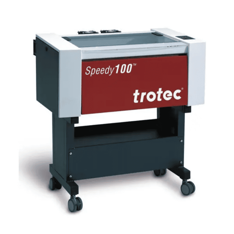
The laser cutter used during this assignment was manufactured by Trotec Laser.
Through a series of test cuts, I developed a better understanding of how power, speed, and focus influence both cutting and engraving performance. A major concept explored during this process was kerf, which is the width of material removed by the laser and is critical when designing press-fit joints. Before machining, the design files were colour coded using the standard laser cutting convention to distinguish cutting operations from engraving.
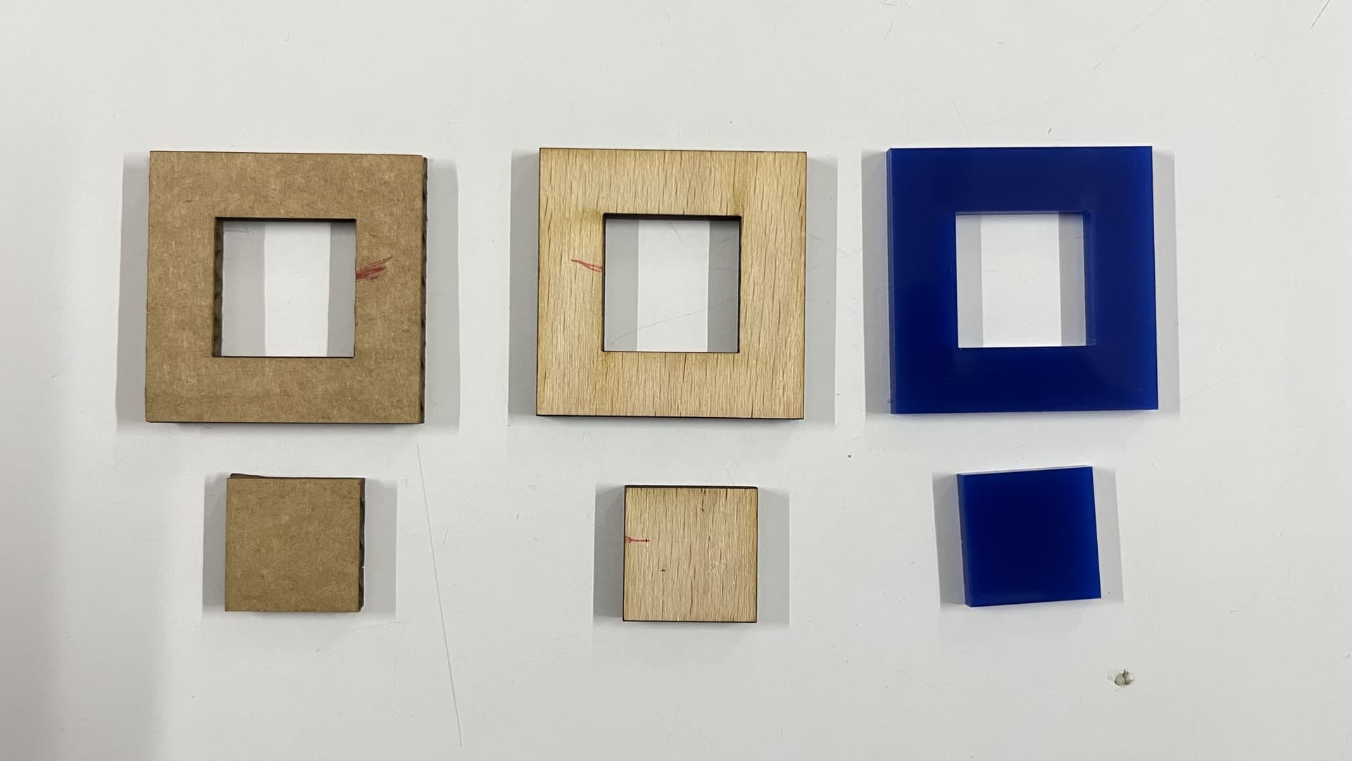
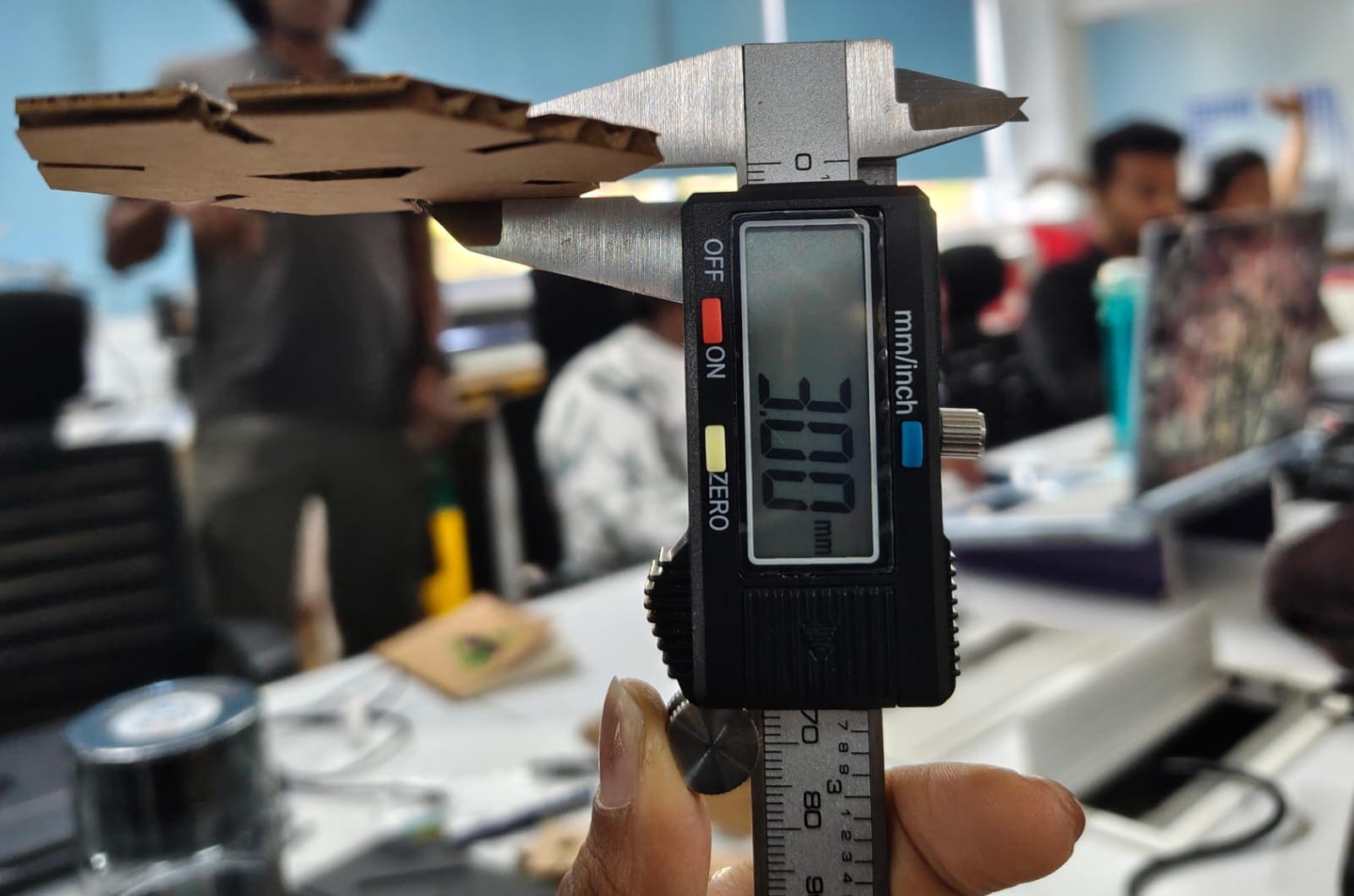
To determine the kerf value, a 40 × 40 mm square containing a 20 × 20 mm inner cutout was laser cut from cardboard. After cutting, the inner dimension of the larger square and the outer dimension of the smaller square were measured. The difference between these two measurements gave the total kerf, which was then divided by two to obtain the effective kerf for the material.
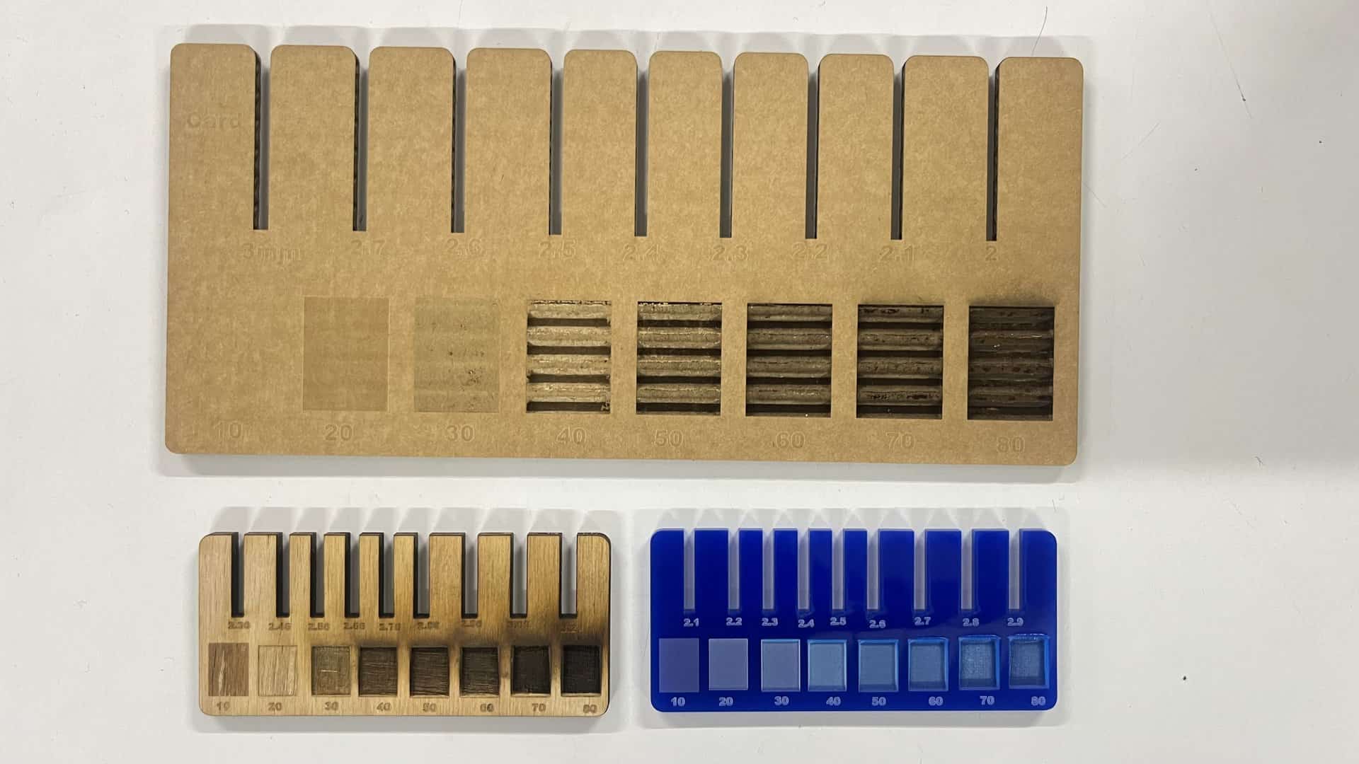
Additional engraving tests were also carried out. Lower power settings produced lighter surface marks, while increasing the power and reducing the cutting speed resulted in deeper engravings. These experiments helped demonstrate how power and speed can be balanced to achieve the desired engraving quality across different materials.
The same characterization process was then repeated for birch plywood and acrylic sheets. The complete testing procedure and results are documented on the Group Assignment page.
Results
The final values determined for the parametric press-fit construction kit in cardboard were:
- Material Thickness: 3 mm
- Compression: 0.2 mm
- Kerf: 0.3 mm
The measured effective kerf values for the remaining materials were:
- Wood: Approximately 0.14 mm
- Acrylic: Approximately 0.10 mm
Individual Assignment
Parametric Design
Parametric design allows values to be adjusted, and all constrained measurements update automatically. These parameters can include weight and material properties. Designs must be parametric to make them versatile across materials, especially when accounting for kerf differences.
CAM Workflow
CAM converts digital designs into machine instructions.
CAD modeling → CAM programming → post processing → production
In software, colors can be assigned to different cut types and even to define cut order. Different speeds and forces can be applied to different colors. These colors are set in Inkscape and transferred to machine software.
Vinyl Cutting Basics
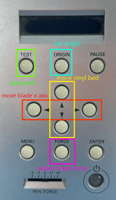
- A movable head along the X-axis
- Adjustable wheels for Y-axis movement
- A knife on the movable head for cutting
Vinyl cutters can cut:
- Self-adhesive vinyl
- Flex vinyl
- Window tint
- Thin PET
The blade angle affects cutting depth, similar to using a blade by hand. These machines use a cutting mat to protect the blade and table surface.
If too much force is applied, the sticker will fall out. Proper cutting involves scoring and then weeding using hands or tweezers.
Laser Cutting Basics
Laser cutters use focused light for cutting. Common types include CO₂, fiber, diode, MOPA, and galvo systems.
- CO₂ laser: 55W
- Diode laser: Combined diodes into one output
- Fiber laser: Used for metals
- MOPA laser: High precision engraving and cutting
Settings include focus, power, and speed rate. Laser cutters can work on wood, metal, glass, acrylic, fabric, cardboard, and more, depending on laser type.
Kerf is the material burned away by the laser beam and must be compensated for in design.
Vinyl Cutting Assignment
About the Machine
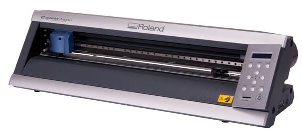
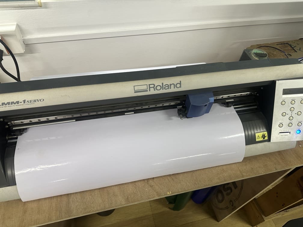
Roland CAMM-1 Servo
The Roland CAMM-1 Servo (most notably the GX-24 and its modern counterpart, the GS-24 ) isa line of professional-grade desktop vinyl cutters and cutting plotters manufactured by Roland DG.
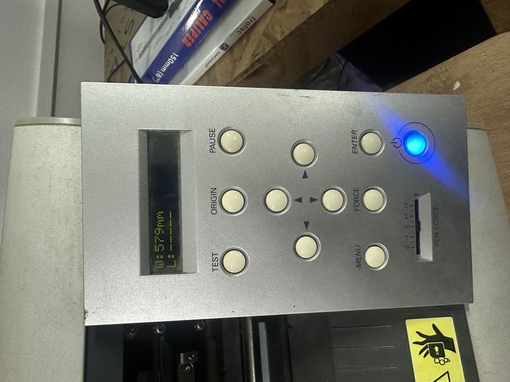
Controls
About the Software
Mods Project
Mods Project (often referred to as MODS CE or Community Edition ) isa modular, open-source, and cross-platform software tool originally developed by the Center for Bits and Atoms (CBA) at MIT.
Process
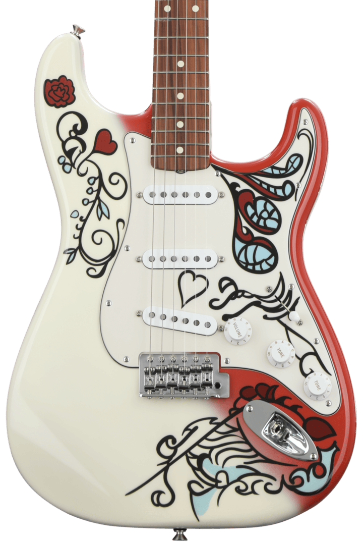
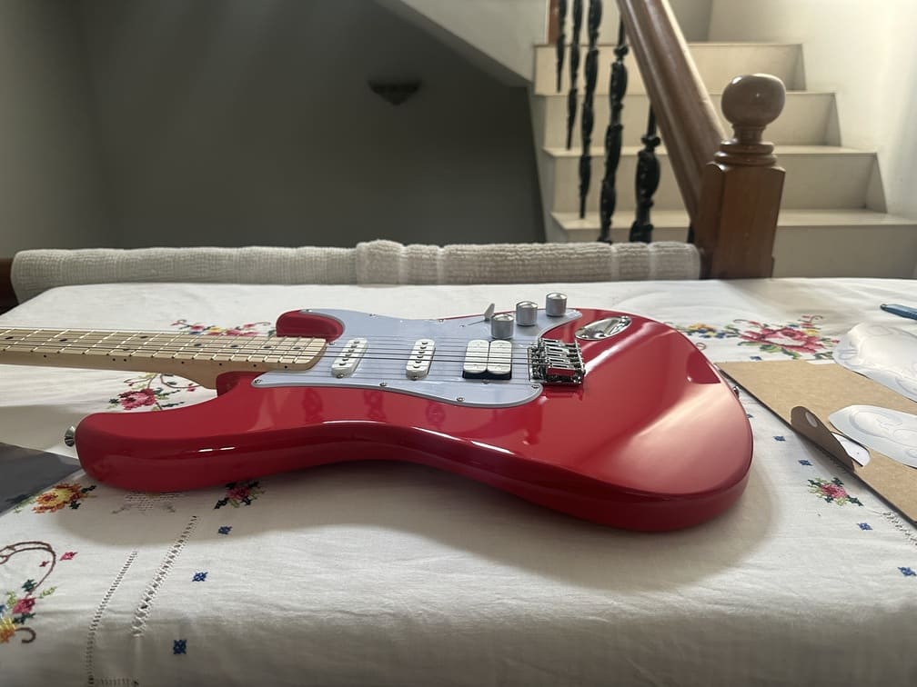
The goal was to add some additional designs to my guitar and make it more personalized. Being a Jimi Hendrix fan, I found a Strat design by Fender dedicated to Jimi Hendrix and loved the design. I transferred it to GIMP to crop the image and increase contrast on the black parts, which made the bit trace mapping process easier.
The software I used to create the vinyl designs was GIMP, as seen below. Used the magic brush tool to separate the design from the background.
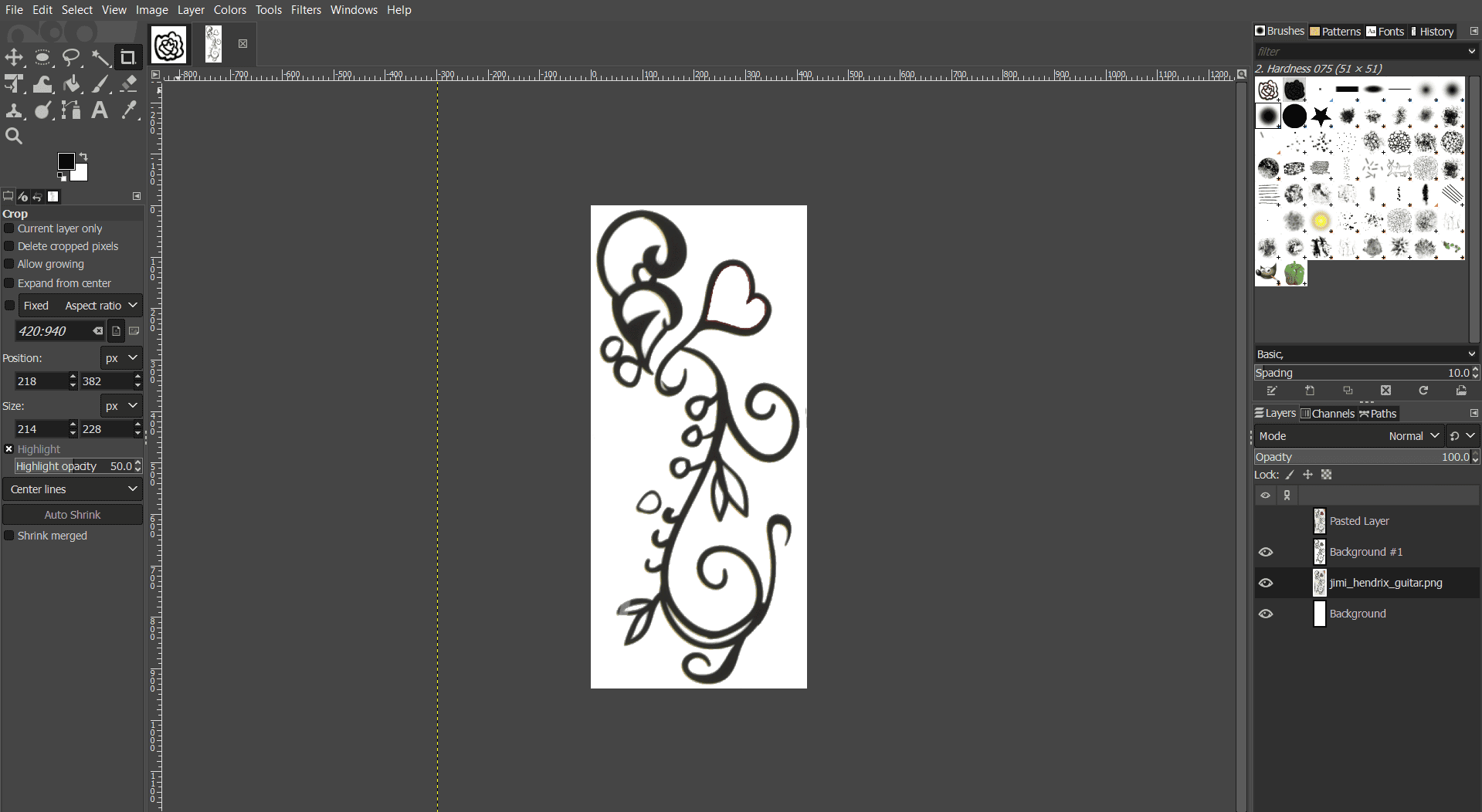
I chose three designs, mainly for the main body. Applying vinyl on the fretboard would be very hard without disassembling the guitar, so I stuck with three final designs.
To get a vector image of the designs, I used Inkscape, as seen below:
I set the width and height manually, but using Ctrl + Shift + R fits it perfectly.
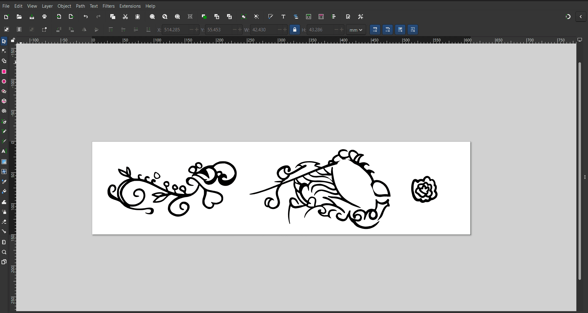
The designs were imported in PNG format and converted to vectors using bit trace mapping. The canvas was set to 609 mm wide to match the two-foot vinyl roll.
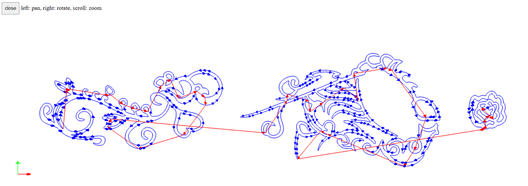
Then the SVG from Inkspace is uploaded to modsprojects, which formulates the movements the vinyl cutter head has to take. It does image processing and gets a clear boundary to follow for the cut.
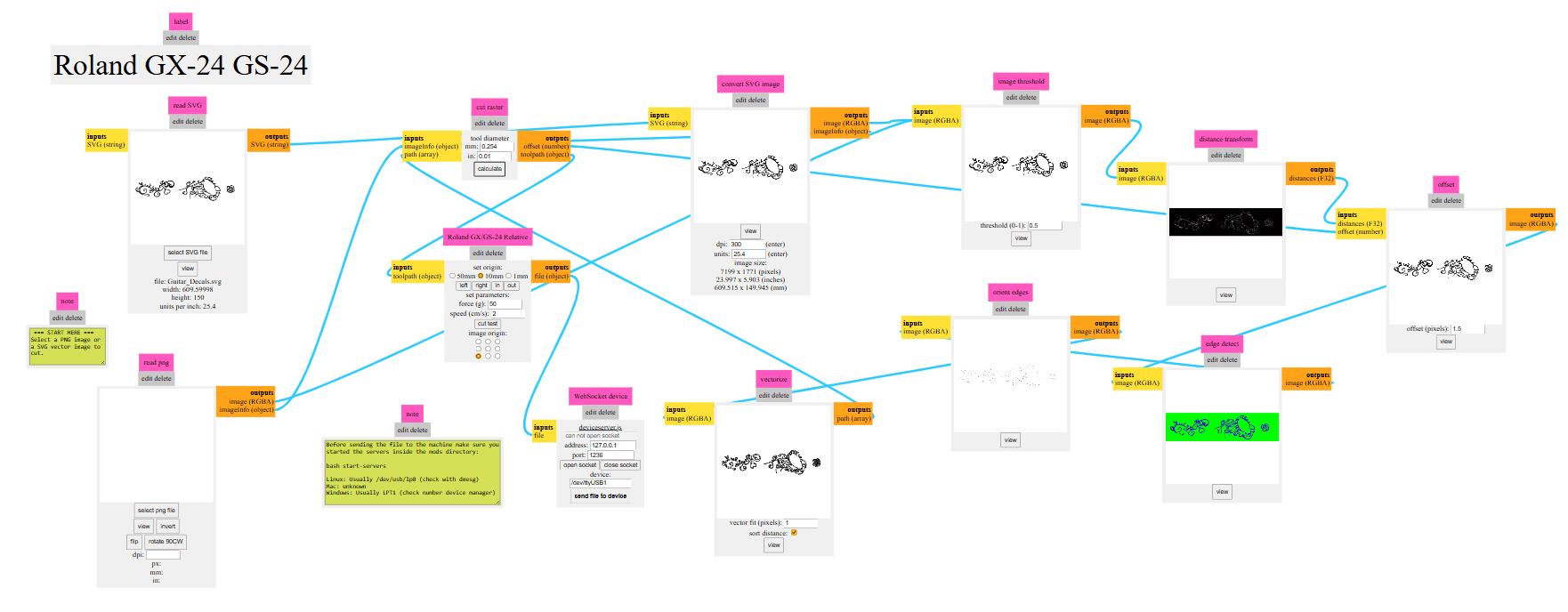
This shows the cutting path followed by the vinyl cutter.
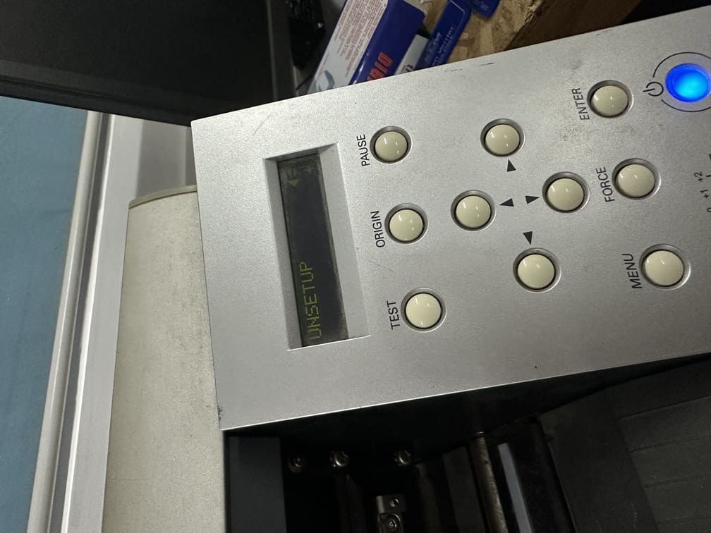
Initially, the job cut off at around 400 mm because the previous setup limited the canvas size. The machine had to be unset and reconfigured by selecting roll and rescanning the canvas.
style="width: 40%; height: auto; display: block; margin: 20px auto;"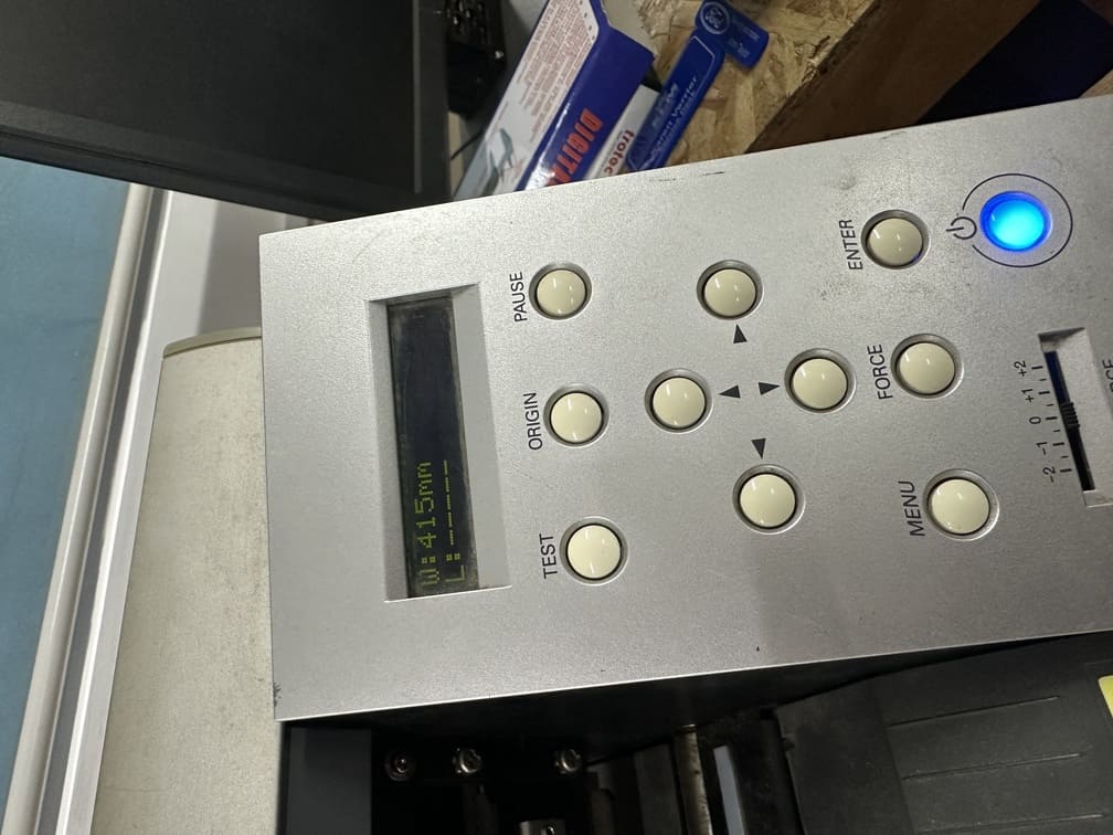
Adjusted the vinyl roll to the last white notch, to accommodate for 2 feet.
This was the speed and force used to cut the vinyl sheet.
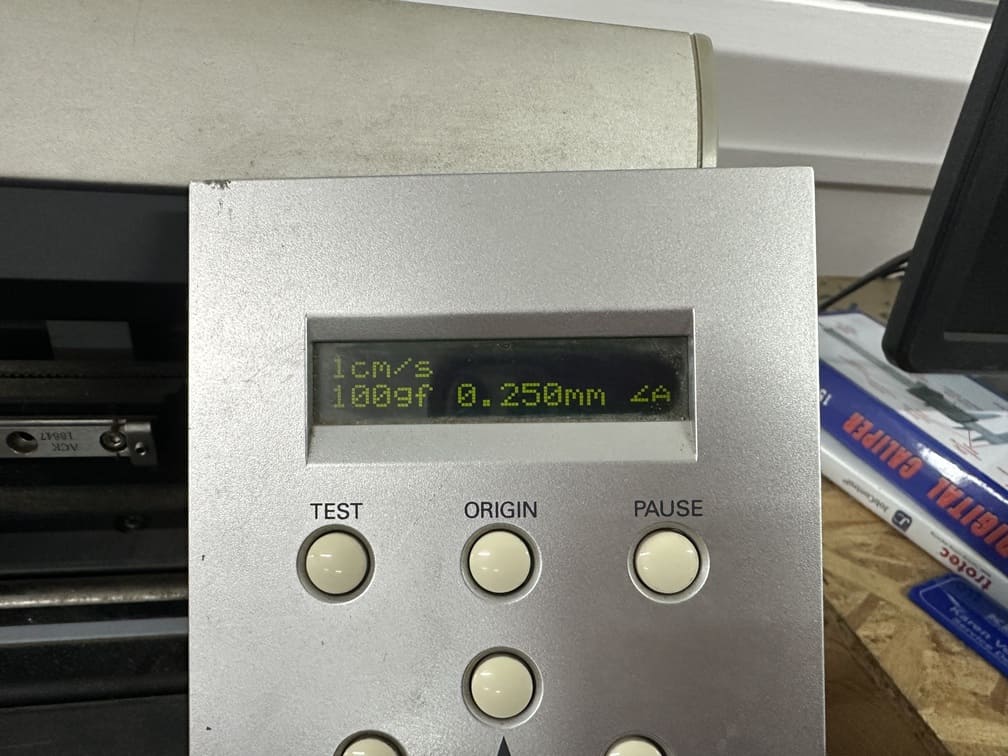
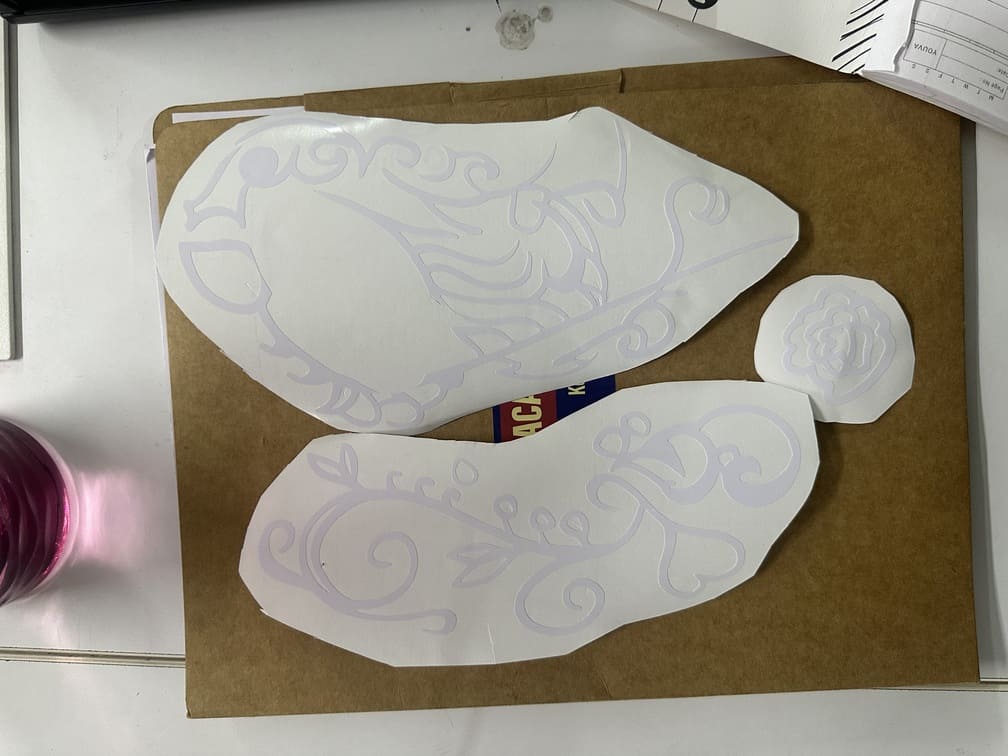
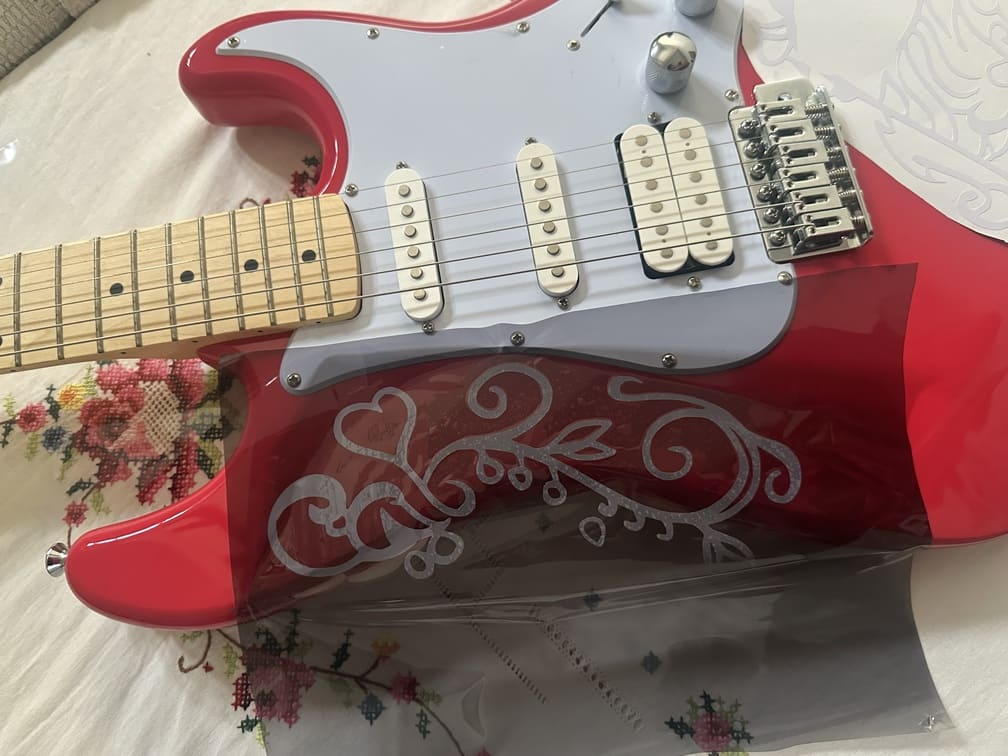
The vinyl was scored and the unwanted parts of the vinyl were removed using a tweezer.
The guitar surface was cleaned with soapy water and a microfiber cloth before applying the vinyl.
Transfer paper was used to lift and align the vinyl accurately.
Final Result
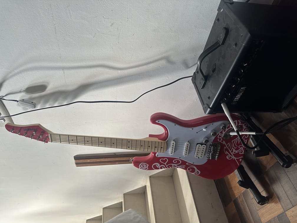
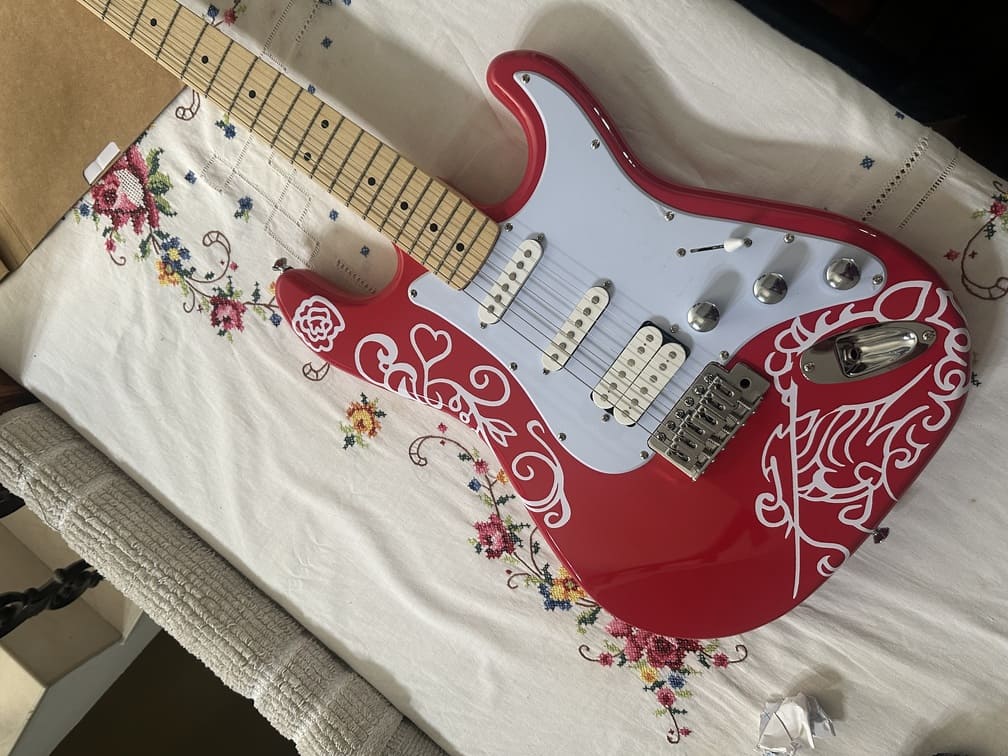
The design slightly overshot the intended size near the output jack, but it did not feel out of place, so the process was not repeated.
Laser Cutting Assignment
About the Machine
The laser cutter used was the Trotec Speedy 100. The Speedy 100 cross is the ideal choice for industrial parts marking and impresses with razor-sharp detail on metals and plastics. It enables large-area marking up to 610 x 305 mm (24 x 12 in) and is ideal for small to medium throughput volumes.
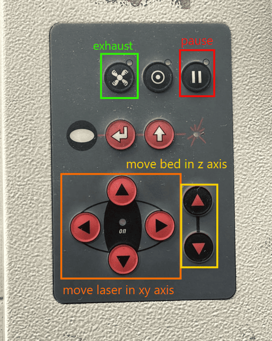
Controls
About the Software
The software used for design was Fusion 360.
Process
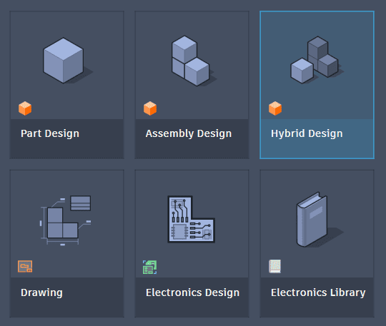
Started Fusion 360 and chose to work with hybrid design, as I wanted access to the arrange function.
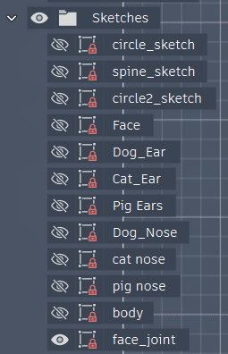
Sketched all the required components.
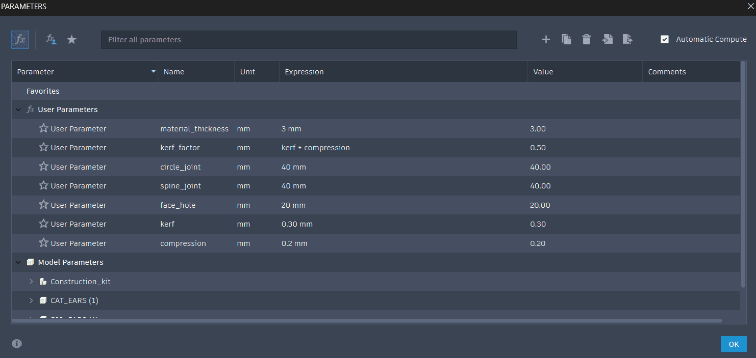
Used parametric design for a few measurements like kerf and material thickness to allow for future variability in material choice etc…
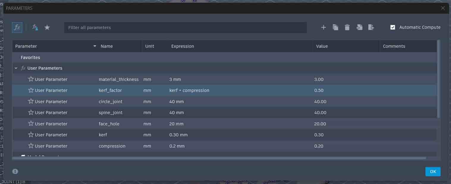
Material thickness = 3mm (cardboard)
Kerf = 0.3mm
Compression = 0.2mm
The full procedure of calculating kerf and determining compression has been documented on the group assignment page.
.jpg)
Nesting / Arranging Components
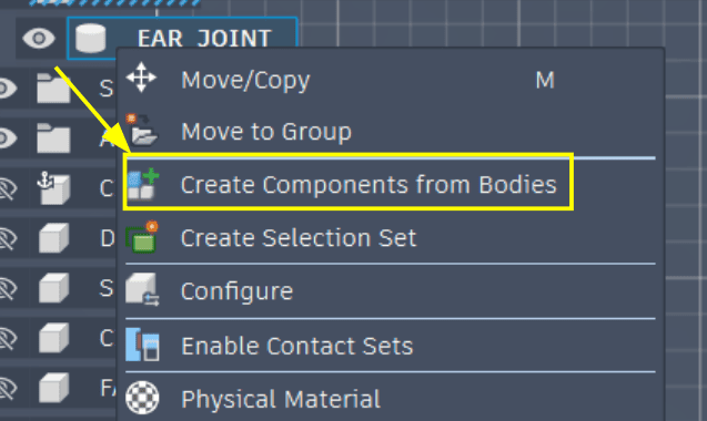
Converted all the sketches to bodies, however to use the arrange function to get all the components on a fixed canvas, I had to convert these bodies to components.
So then I got a stack of all my components.
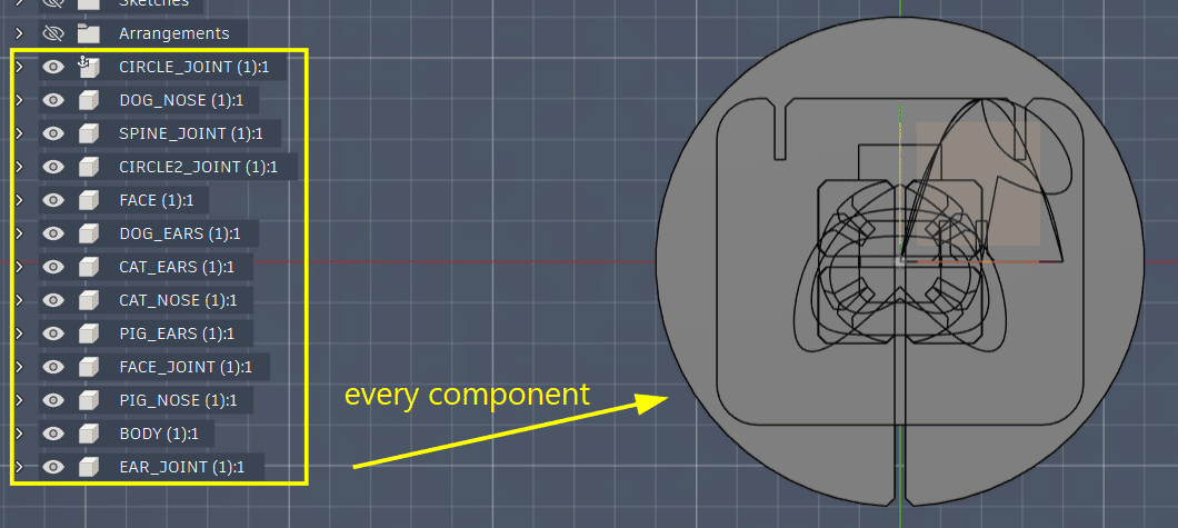
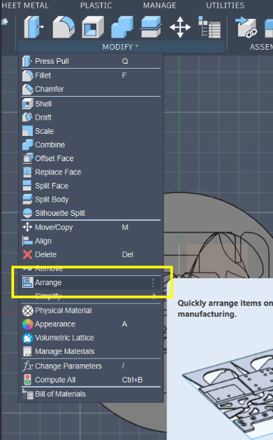
Now using modify → arrange I can arrange all of these components.
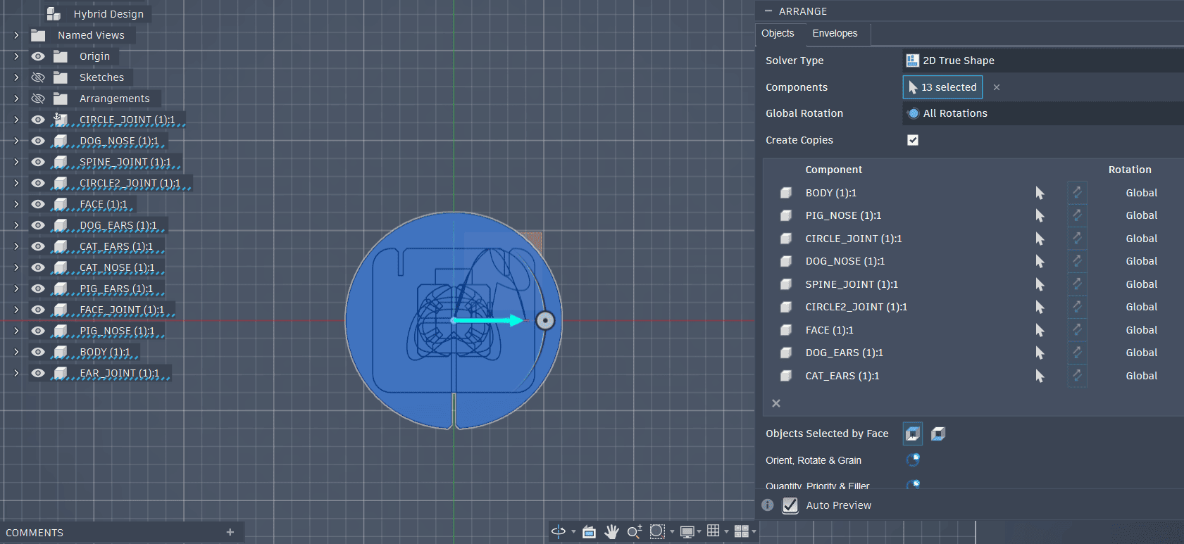
In the objects tab select all the components you want to be arranged.
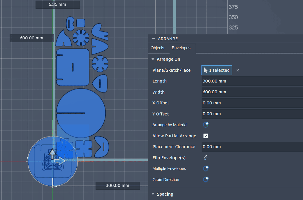
Now in the envelope tab you can choose which plane you want the components to be arranged, you can set the canvas size on which the components will be arranged.
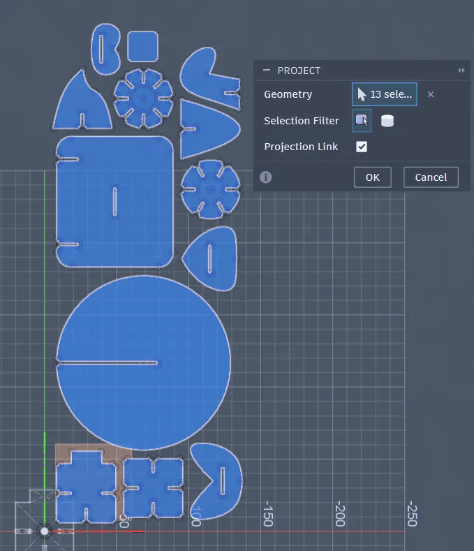
Now to export this to Inkscape or whatever vector software you want to use we need to project the surface of all the arranged components, select one face and then click P and then select all the other faces to get the new sketch of all the components.
Sketch complete.
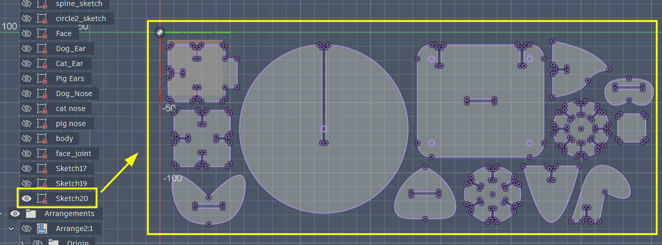
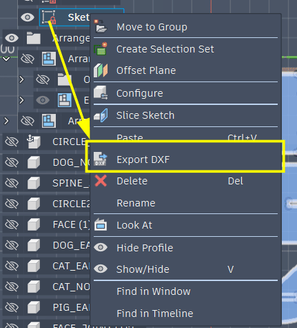
Now export this sketch as a DXF output file.
Now because of the weird curves on the faces of some of my components we can’t directly import this DXF file into Inkscape, it just won’t recognize those curves. So we’ll have to use other software like Rhino or Affinity. I’m going to use Affinity.
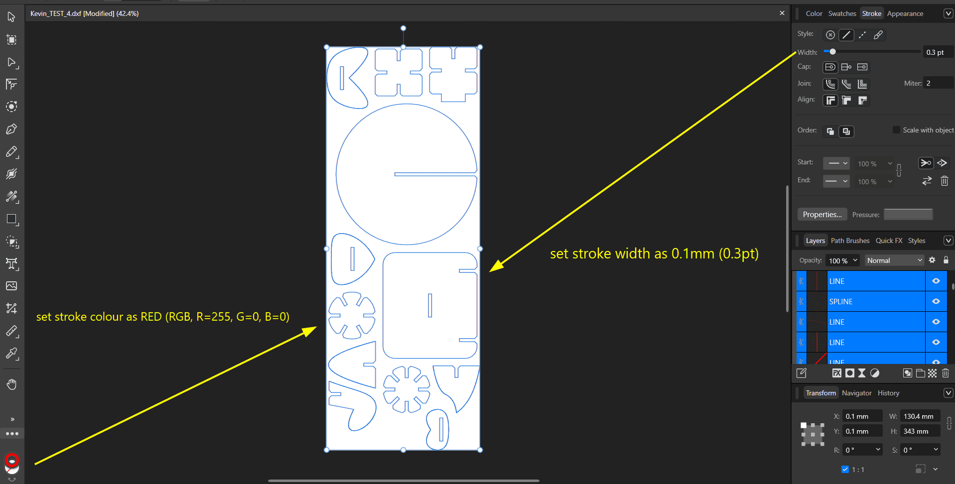
In Affinity change the stroke width and stroke colour, this is done for the job control software to recognize where are the cut lines.
Ideally we would print to the Trotec directly from Affinity, but as the workstation connected to the Trotec laser cutter doesn’t have Affinity installed I exported the file as an SVG then opened it in Inkscape, then printed it from the software.
However because of this at the problem curves the printer would lose most of its speed and slowly follow along the nodes of the curves, could be a problem for larger cuts.
Set the laser to the origin point you would like, and then snap the job box right at the pointer which indicates the laser position on the software
.jpg)
Exported it as SVG small size, so it compressed it a little bit, redoing with a high quality SVG output.
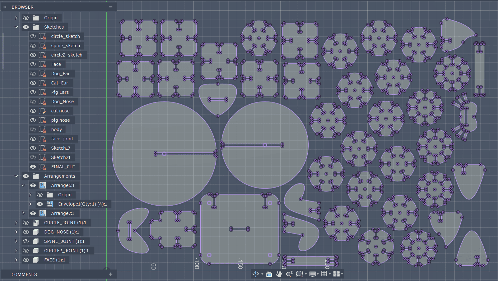
First I prepared one of each different type of cut just to test fit. Then I multiplied the components I need multiple of and arranged them again.
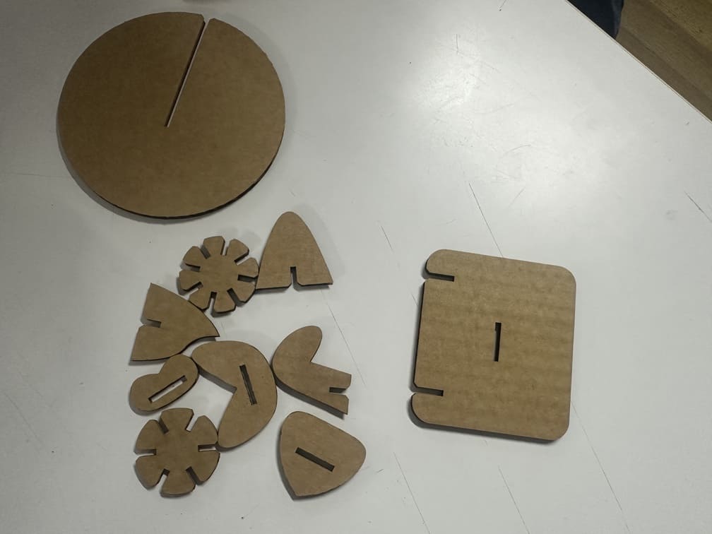
Press-Fit Joint Testing
The Test cut came out well, but because of Affinity and choosing the wrong SVG export(small size) it shrunk all my pieces.
The cuts were pretty clean.
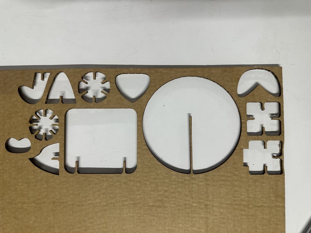
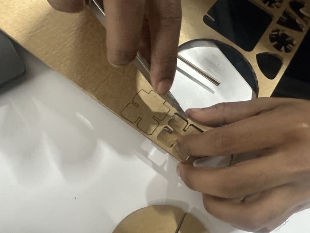
A few pieces were not perfectly cut, so had to use a blade. This was not due to the cutting settings, but more because the cardboard had a bend toward on side.
First test complete!
Bulk Cutting / Mass Production
Got the projection of all faces, made it into a sketch then exported the DXF file. Then imported that file into Affinity. Changed the stroke length and changed the stroke colour to red. Exported into SVG for Inkscape.
.jpg)
.jpg)
Then exported that SVG into Inkscape, saved, corrected the dimensions as Affinity tends to slightly change it to closer approximations, then sent the job to the Trotec Speedy 100 for printing.
Open the .dxf file in inkscape, set the canvas to the imported vectors using ctrl + shit + r, then change the stroke colour to red, and the stroke width to 0.1mm.
.jpg)
Press ctrl + p, to open the print tab and you can send the .dxf job to Jobcontrol. The native software for the Trotec.
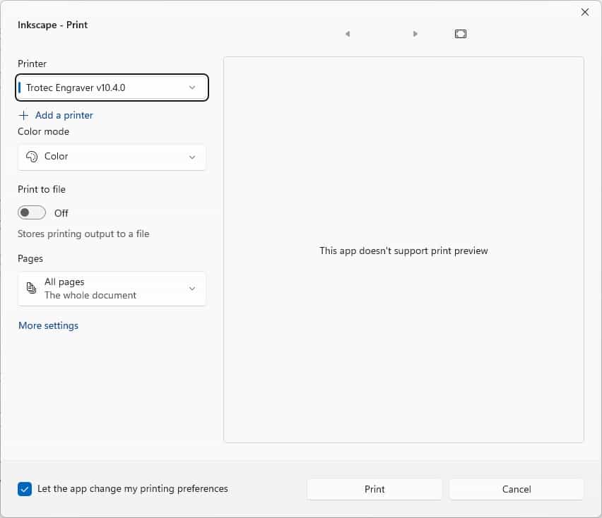
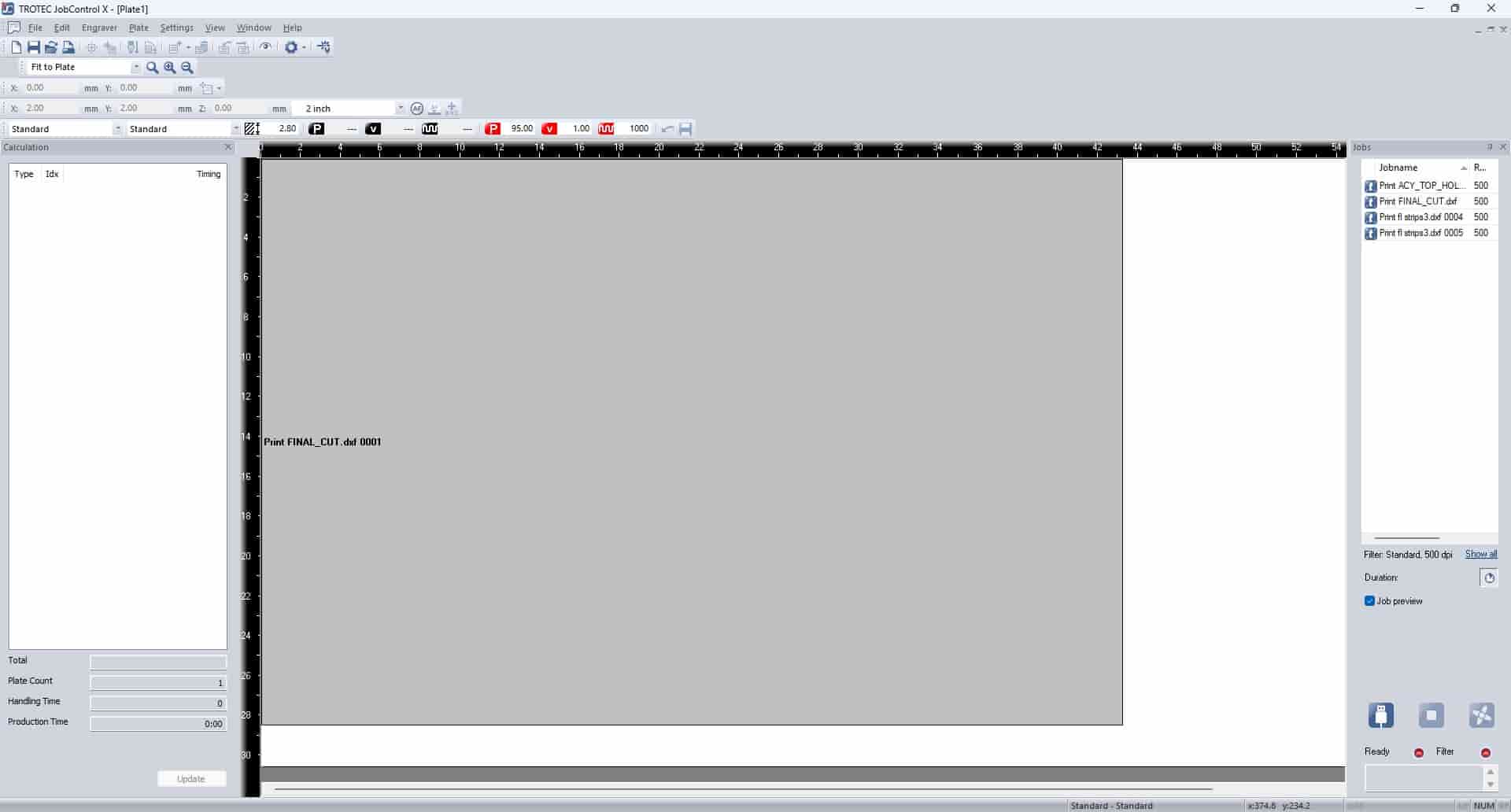
In Jobcontrol, connect the software to the laser cutter and then send the print job.
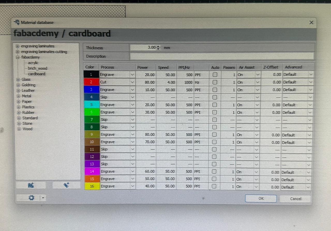
The cutting settings used.
Here all the stroke colours were set to red, this was to use the cutting settings 2 as seen below. Power 80, speed 50, HZ 1000.
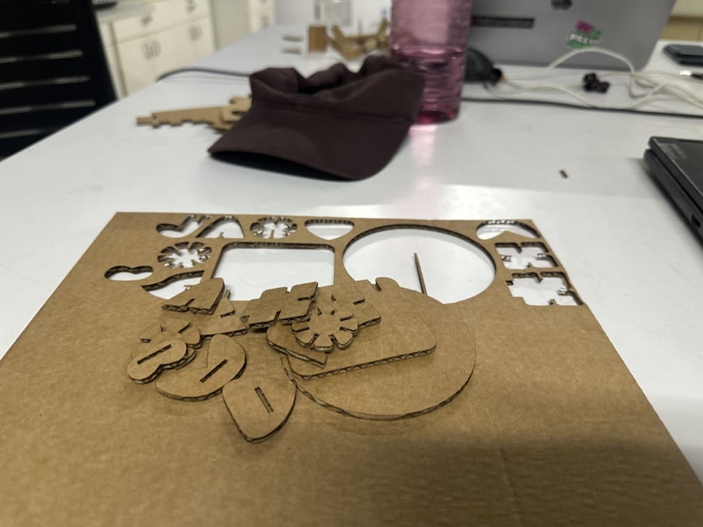
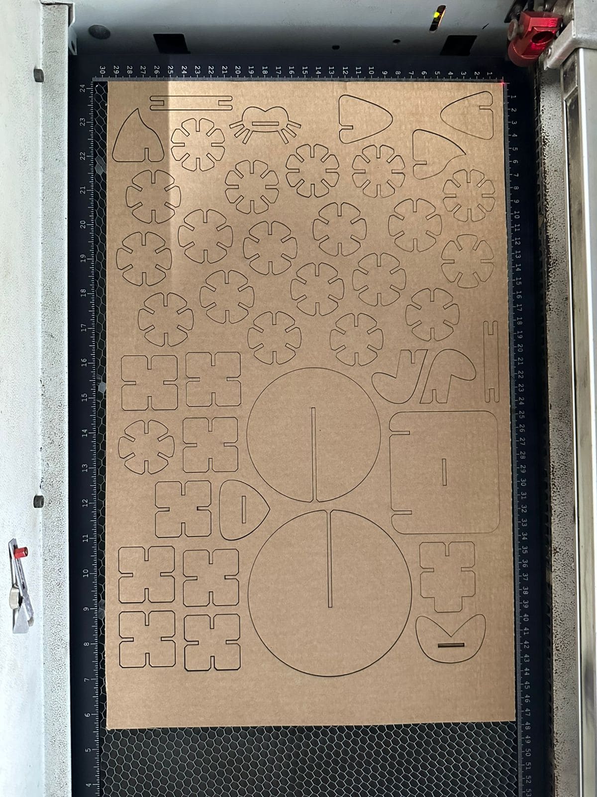
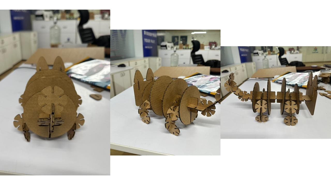
The final cut fresh out of the laser cutter.
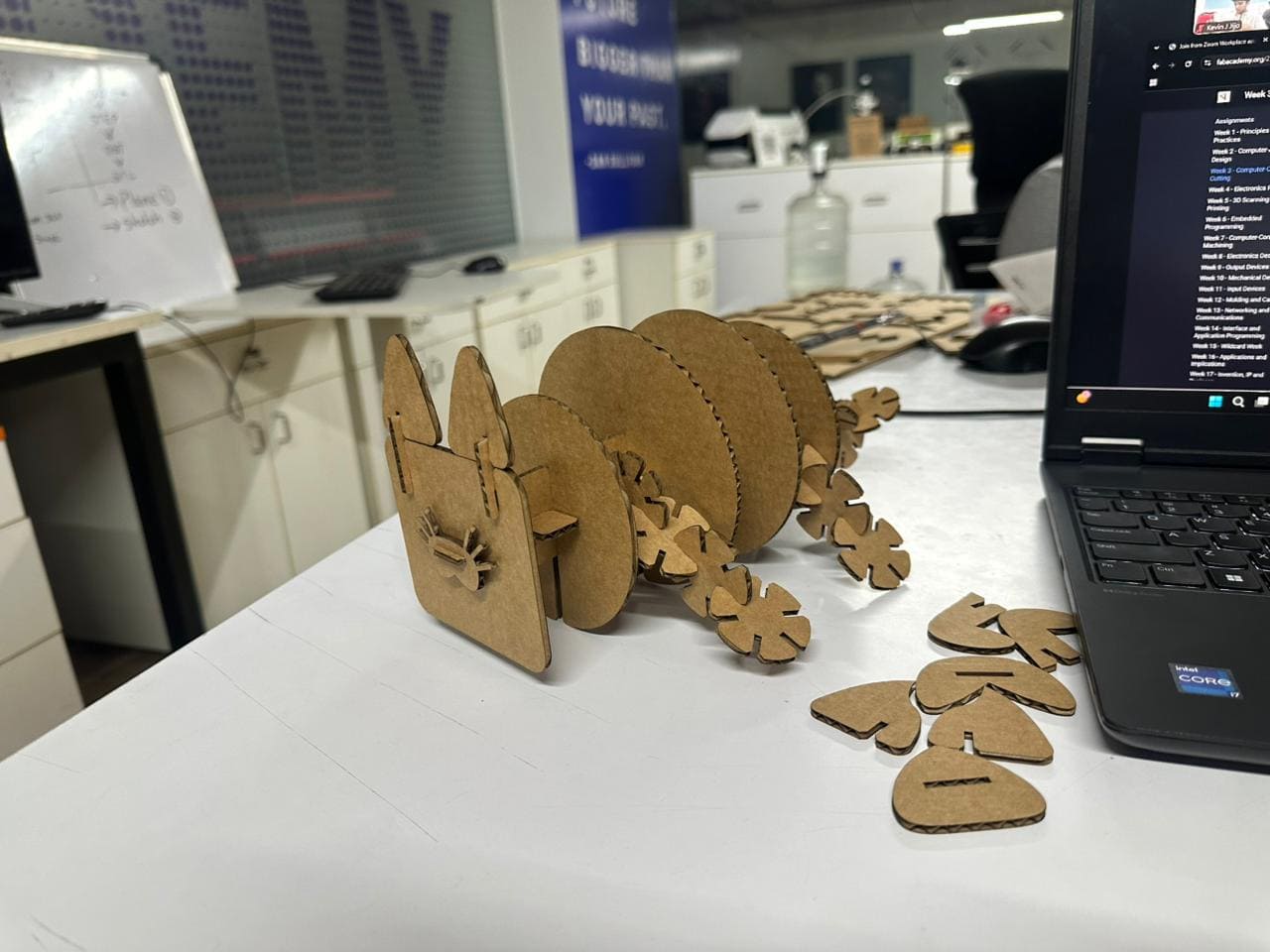
Assembled and viola!
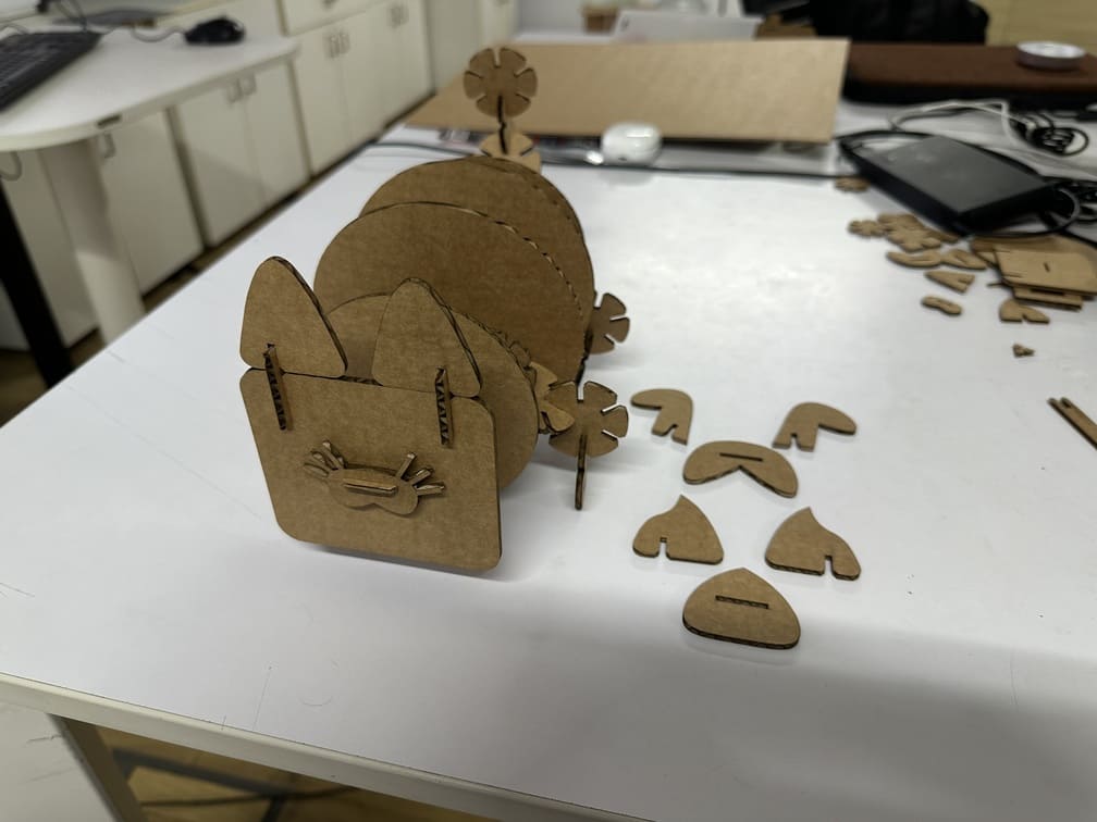
It’s a multipurpose domestic animal friend (trademark pending), with interchangeable faces between a dog, a cat, and a pig.
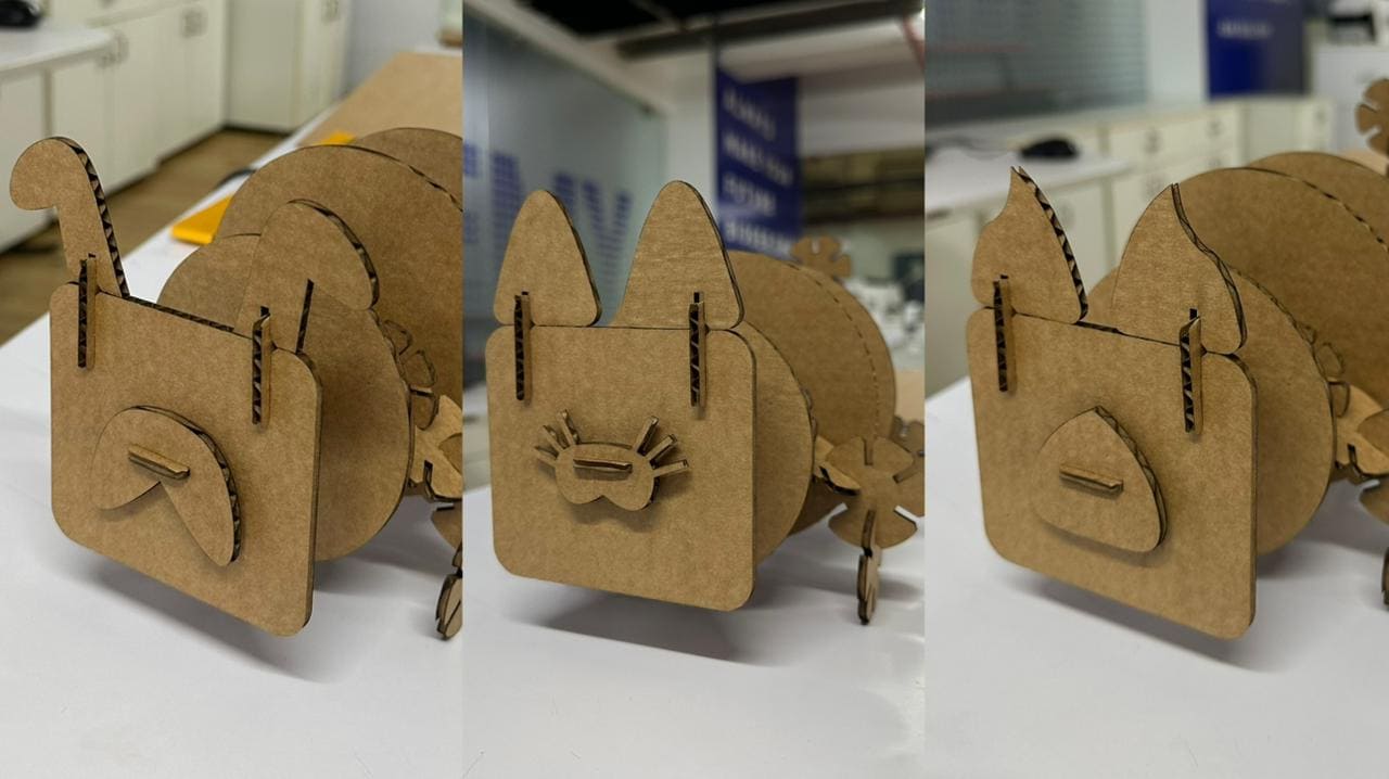
Sleeping fat cat.
Villain Shot
The following links contain the project files produced for this assignment using the respective software tools.
- Fusion 360: Construction kit
- SVG: Guitar Decals