Computer Controlled Machining
Task:-
Group assignment:
Do your lab's safety training.
Test runout, alignment, fixturing, speeds, feeds, materials and toolpaths for your machine.
Individual assignments:
Make (design+mill+assemble) something big
Instructors for this week: Mufeed, Revisankar and Saheen.
Highlights of the week
Overview of Group Assignment
For the group assignment, we focused on understanding the safe operation of the ShopBot and the workflow required for CNC machining. We first reviewed the machine's safety procedures, including emergency stopping, personal protective equipment, safe behaviour around the machine, and pre-operation checks such as inspecting tools, securing material, and verifying the emergency stop system.
After understanding the safety requirements, we designed jig in fusion 360 and machined a
test jig to evaluate the machine's performance by checking parameters such as runout, feeds, and speeds.
Using VCarve, we created the CAM toolpaths for the test pieces and then post-processed them on the ShopBot.
From these tests, we identified the press-fit clearance value of material_thickness - 0.1 mm for our
plywood joints.
For detailed information, refer to: Week 7 Group Assignment
Individual Assignment
Overview
This week's individual assignment involves designing and fabricating a furniture piece using the CNC ShopBot.
One important constraint, and a key learning, was that we could not use fasteners like screws or nails. All the parts had to be assembled using only joints.
Design Concept
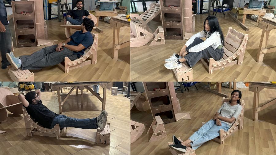
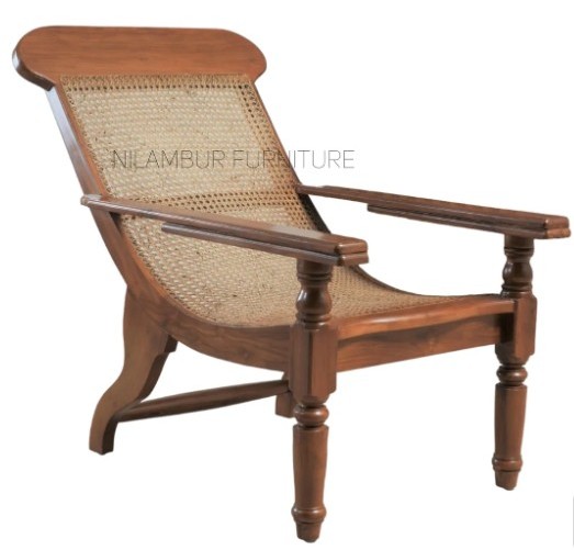
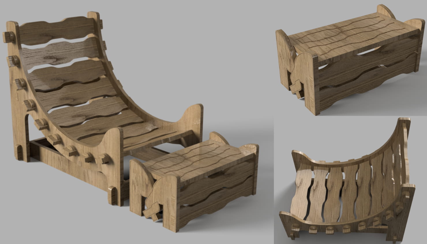
I wanted to design a Charukasera-style furniture piece where kids( not just kids, you can too) can lie down, lean back, and relax comfortably.
Since it is meant for resting, I wanted the furniture to feel warm, safe, and full of affection.

I really like how elephants show love. They gently lean their heads on each other and twist their trunks together in a caring way. That moment feels calm, protective, and soft — exactly the feeling I wanted children to experience while using this furniture.
Form development
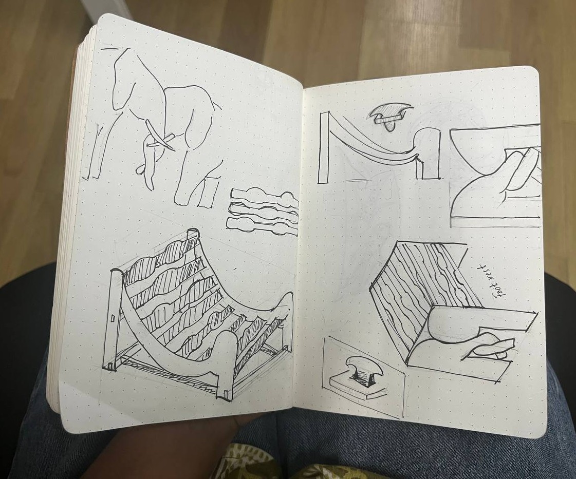
The legs of the chair are inspired by the curved shape of an elephant's trunk.
These trunk-like forms extend and connect to the other leg and the footrest, visually representing two elephants standing close with their trunks twisted together.
I believe this connection provides structural support and also conveys a sense of bonding, calmness, and emotional comfort through the design.
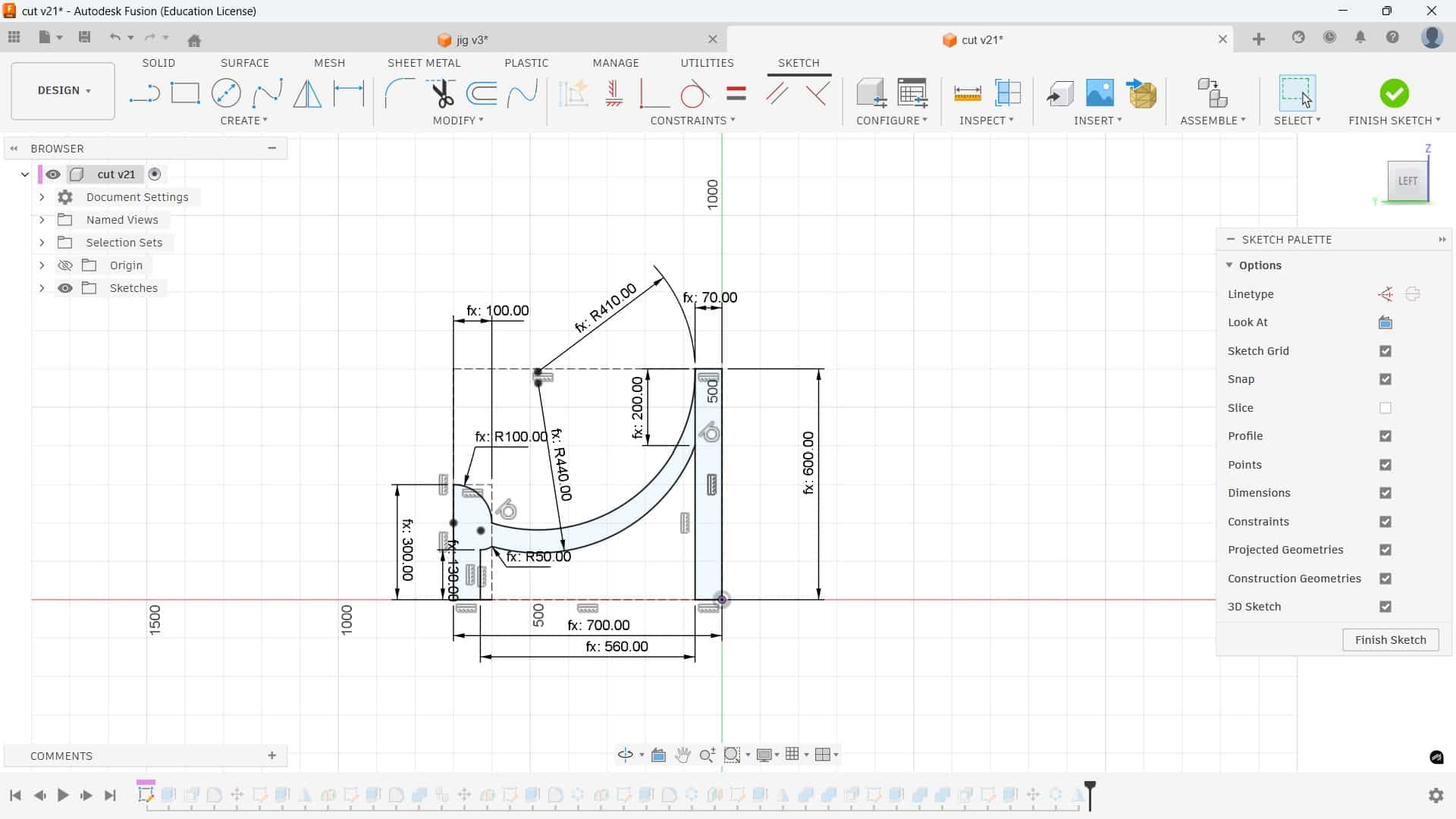
Designing the Model in Fusion 360
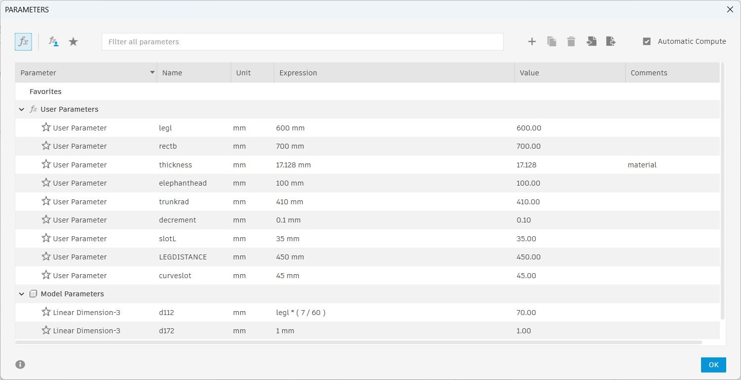
I created the furniture model in Fusion 360 and worked on making it parametric so it could adapt to different machines and materials.
This was the most challenging part of the process.
Before machining on the ShopBot, we produced a test model using cardboard on the Trotec laser cutter, which is why the material thickness should be in parametic.
To manage this, I made the material thickness parametric in Fusion. This allows me to change the thickness anytime without disturbing the overall design.
However, even though I added parameters for other dimensions, some relationships were not properly constrained. Because of this, changing parameter values does not scale the entire structure correctly.
So whenever I need to resize the full model, I use the Scale tool to adjust it proportionally.
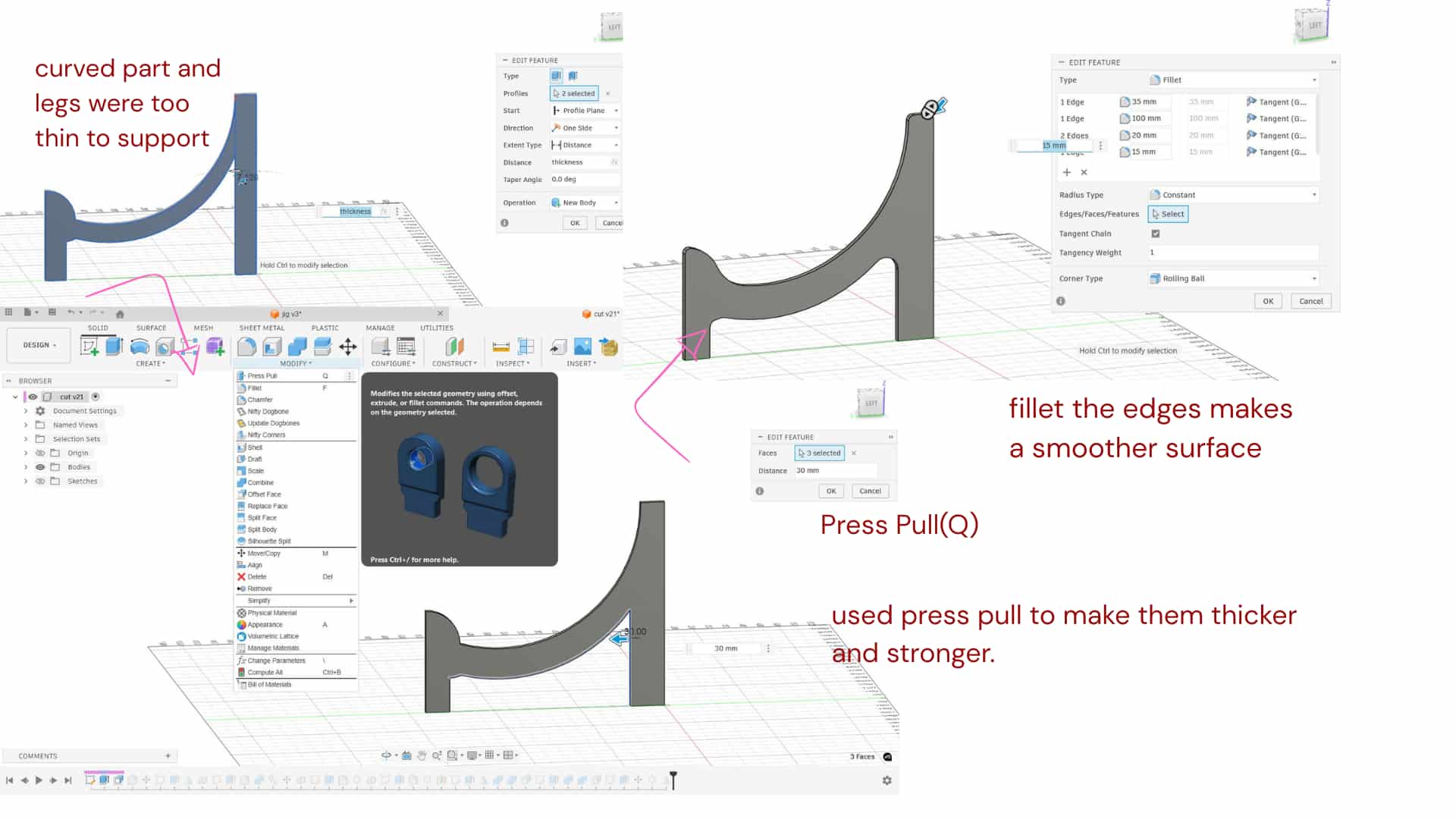
Press Pull
Press Q, select a face, and drag it inward to remove material or outward to add material.
The curved part and legs were too thin to support the chair properly, so I used Press Pull to make them thicker and stronger.
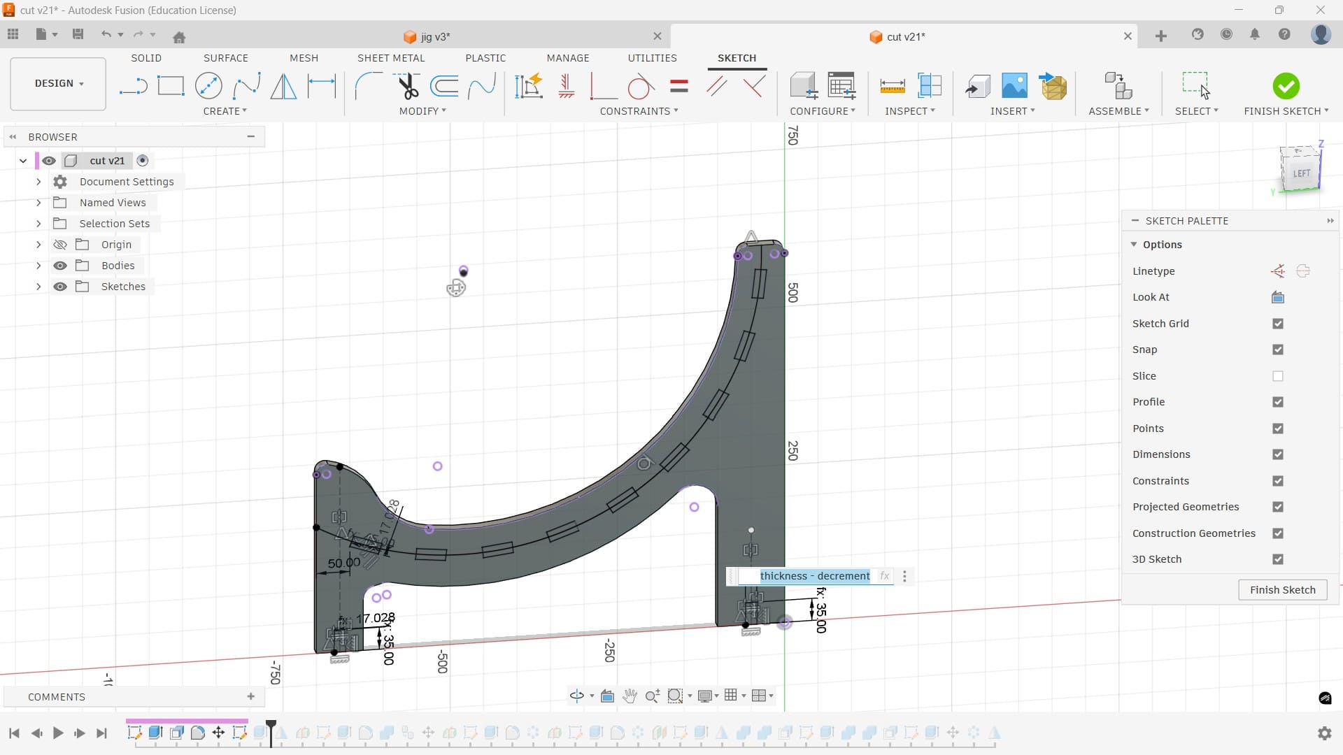
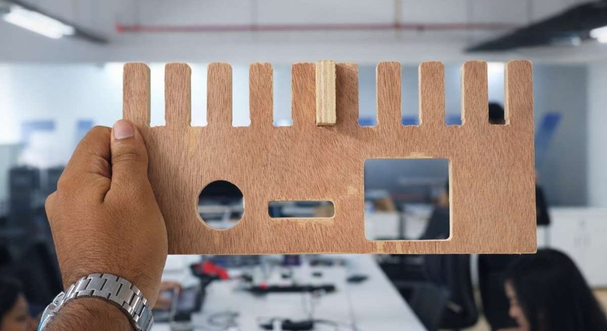
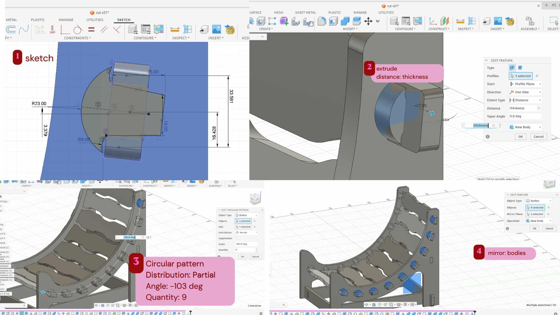
To make the slots on the curved part, I drew an arc between the legs and created a 45 mm curved slot. The slot width was set to material thickness minus 0.1 mm clearance. Using a circular pattern, I made 9 slots along the curve, and added 35 mm slots at the bottom of the legs.
Support planks
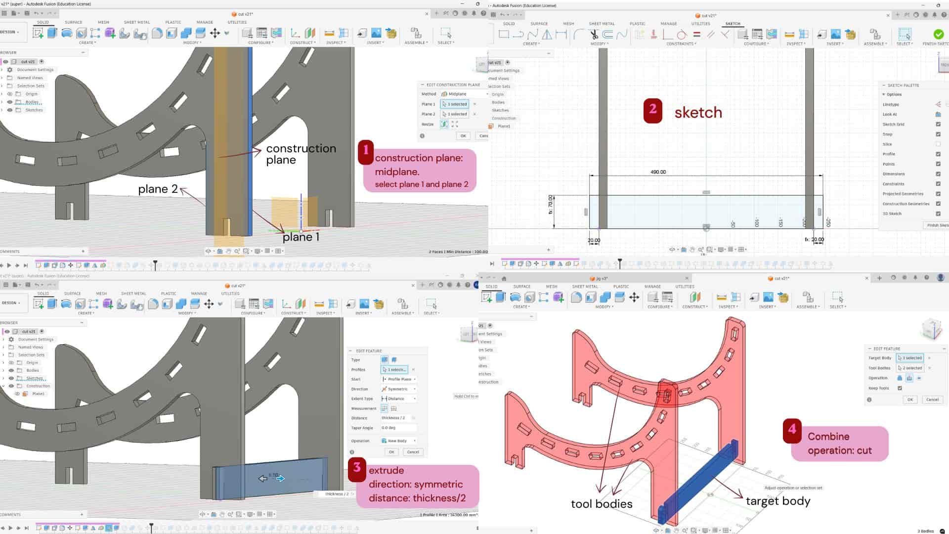
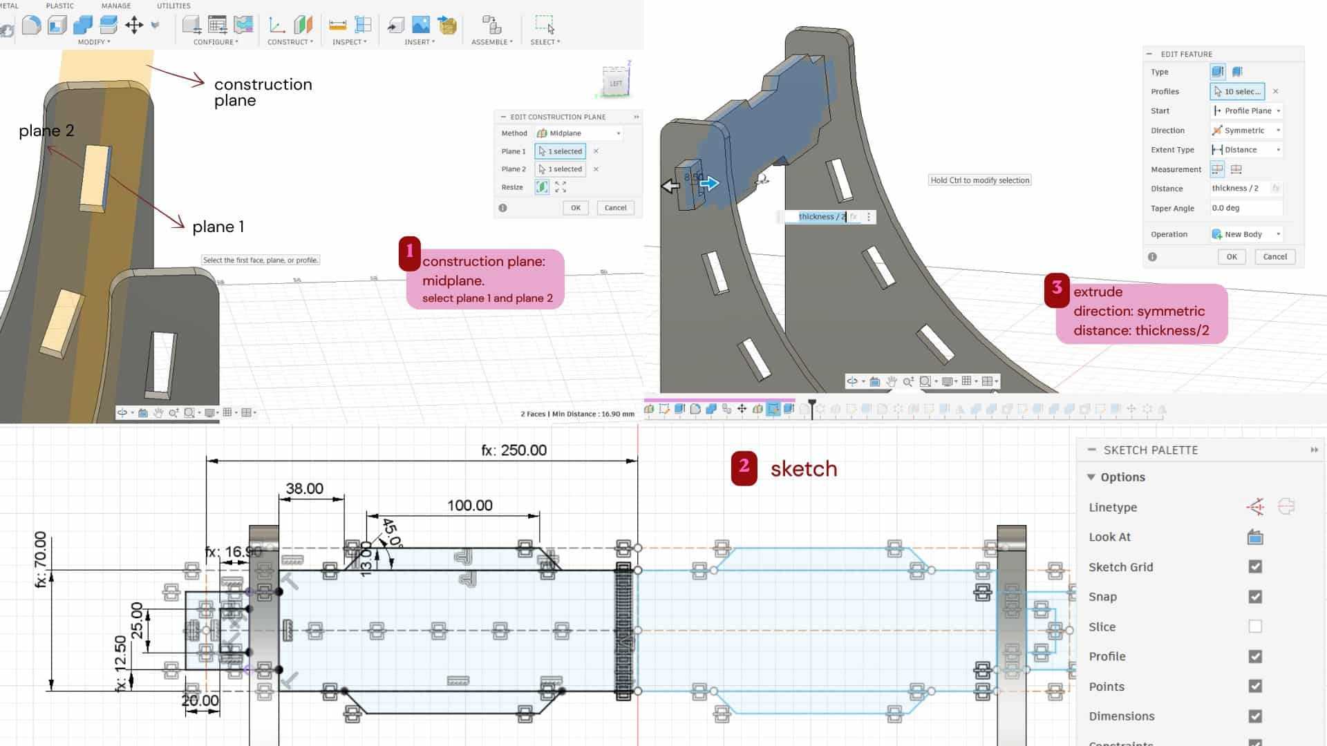
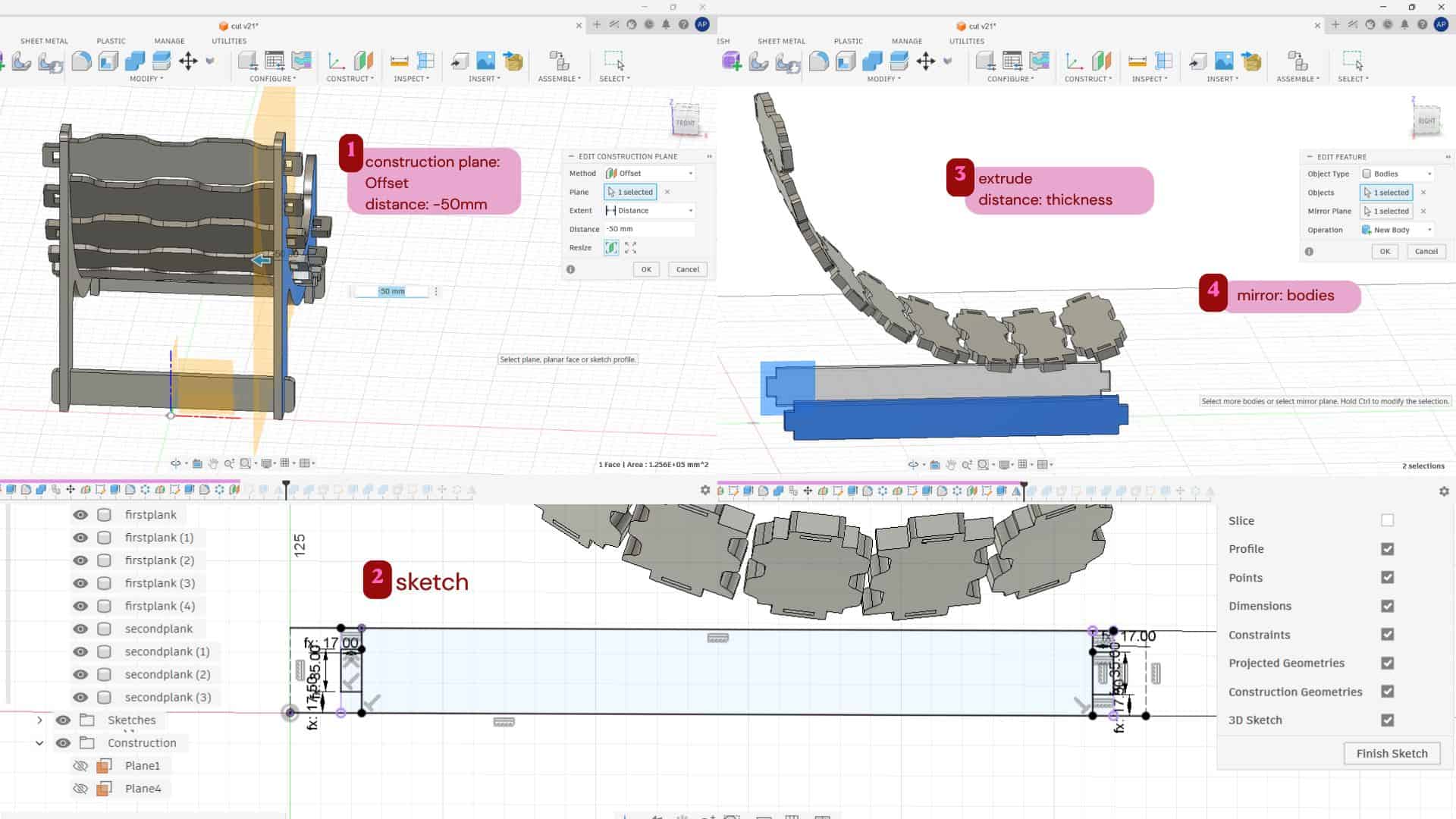
I used a construction plane: mid-plane between the two inner faces of the chair legs and sketched the supporting piece on it.
Then I extruded it symmetrically using half of the material thickness on both sides.
After that, I used the Combine tool to create the slot for joining it with the main legs and added fillets.
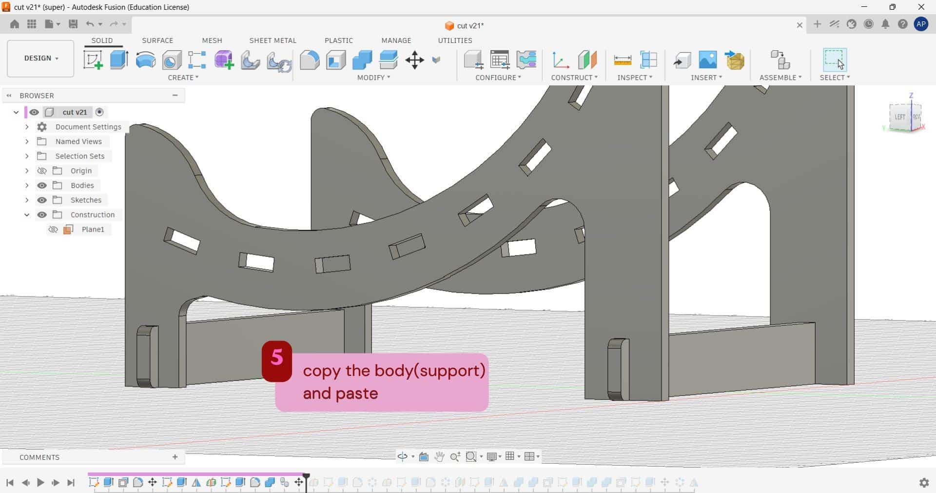
Once the back support was completed, I copied the same body to the front side of the legs, combined it, and added fillets there as well.
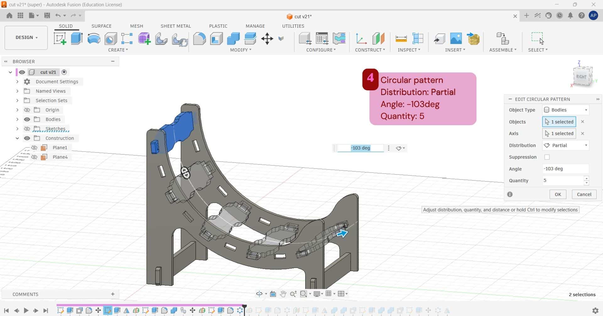
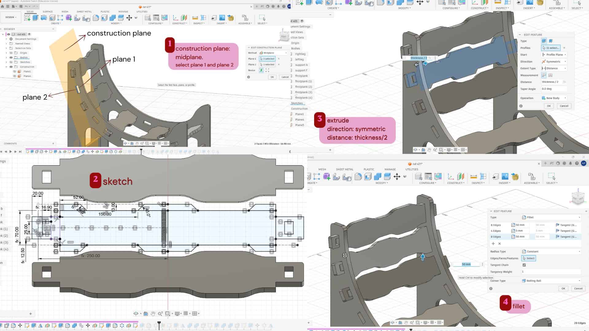
For creating the first plank, I made a construction mid-plane between the slots in the leg and sketched the plank on it. Then extruded it symmetrically and added fillets to the edges. After that, I used a circular pattern to create 5 planks, with the angle set to -103° and partial distribution, since I wanted to leave space in between for the other designed planks.
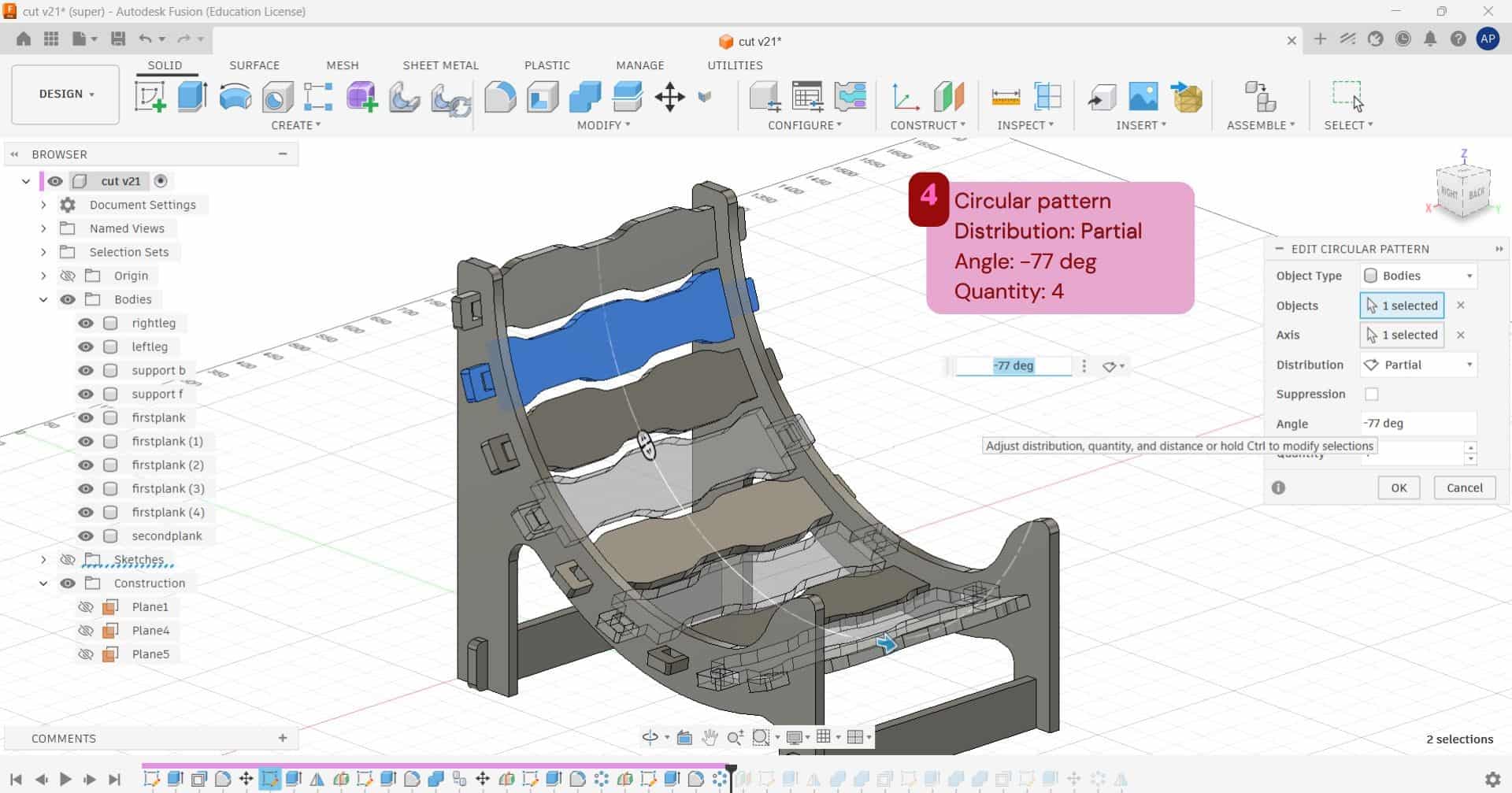
For the second plank, I followed the same process as the first one, but with a different design. After creating the plank, I used a circular pattern to make 4 planks, with the angle set to -77° and partial distribution.
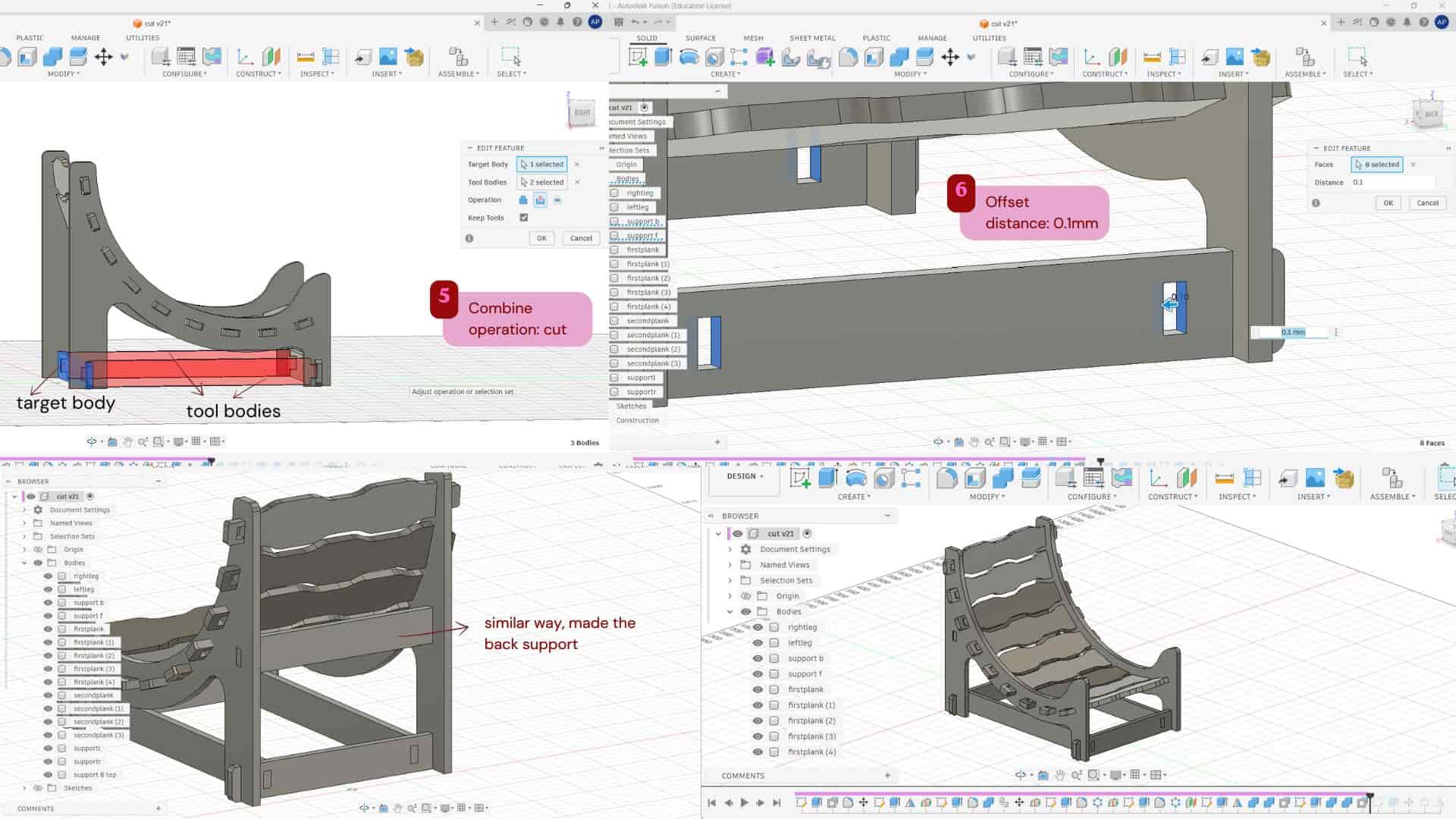
To make the furniture more stable and give extra support, I added side support planks at the bottom using a tab-and-slot joint. I first made the support plank, then used the Combine tool to create the slots in the existing supports so the plank could fit into them. I also gave a 0.1 mm offset to the slots for a better fit. In the same way, I added a support plank at the back as well.
To hold the seating planks in place and prevent them from falling apart, I created pins that fit between the legs and plank pieces. I sketched the pin profile and extruded it, then used a circular pattern to create 9 pins with an angle of -103°. After that, I mirrored them to the other side.
Footrest
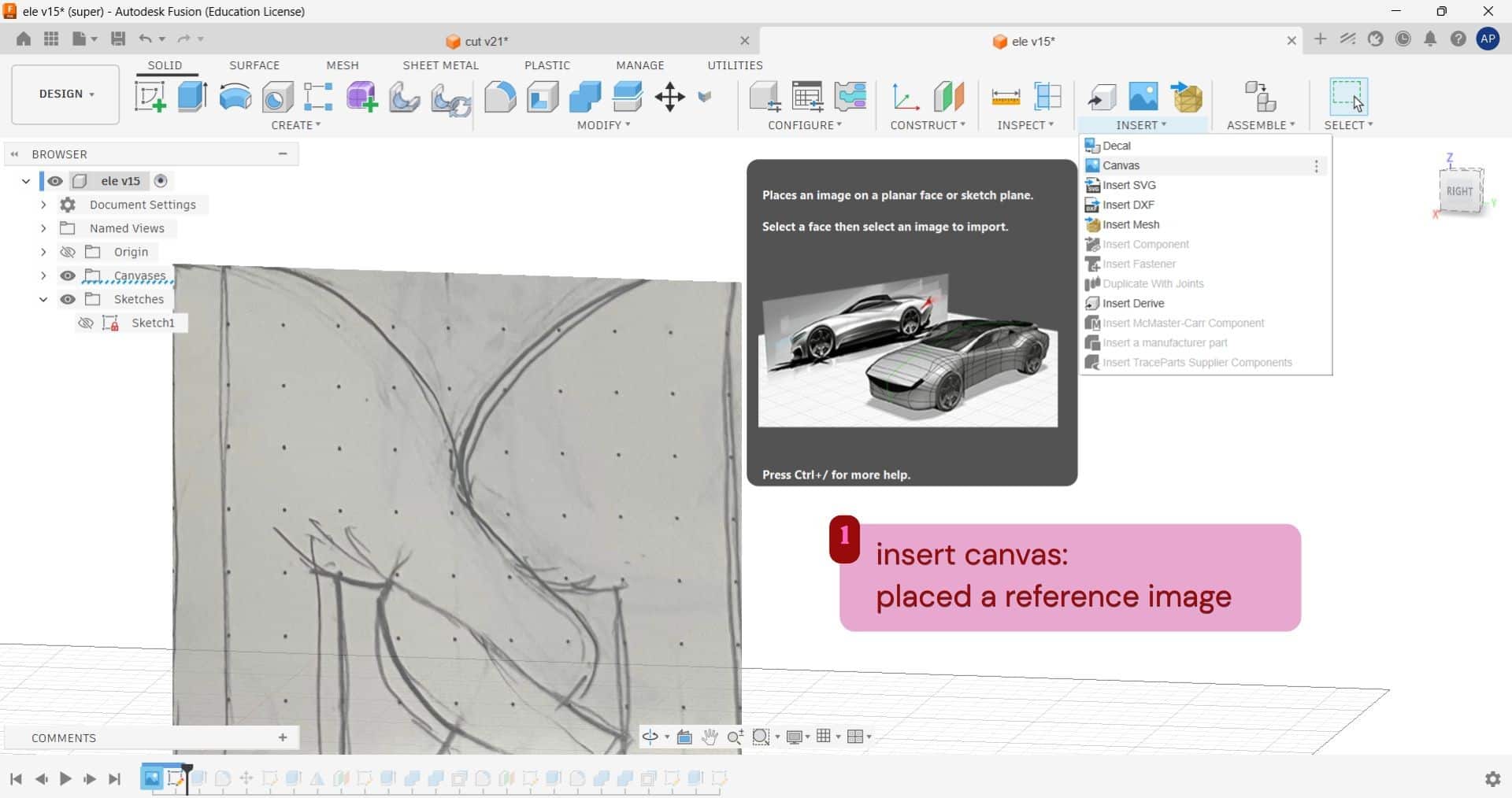
For making the side planks of the footrest, I wanted the form to look like two twisted elephant trunks.
I first sketched the idea in my notebook and then inserted it into Fusion using Insert Canvas as a reference image.
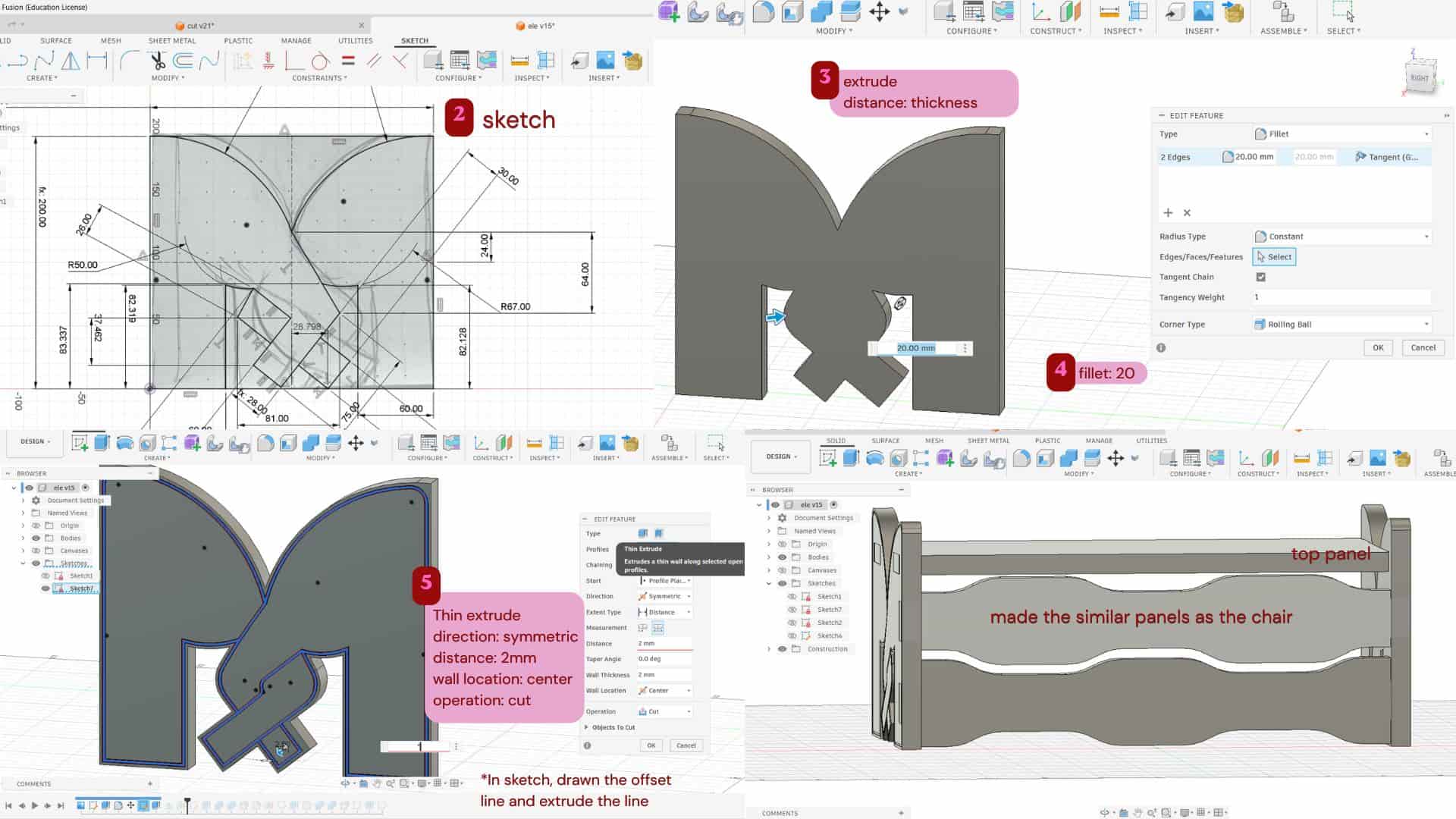
Based on that, I sketched the profile and extruded it, then added fillets.
To make the twisting trunk detail more visible, I created another sketch on the profile, created an offset to it, and used Thin Extrude with Symmetric direction,
2 mm distance, Wall Location: Center, and Cut operation.
I also used tab-and-slot joints to connect the footrest planks parts.
On the front side, I created a similar plank design like the seating area plank on the chair, and then made the top plank to rest the foot.
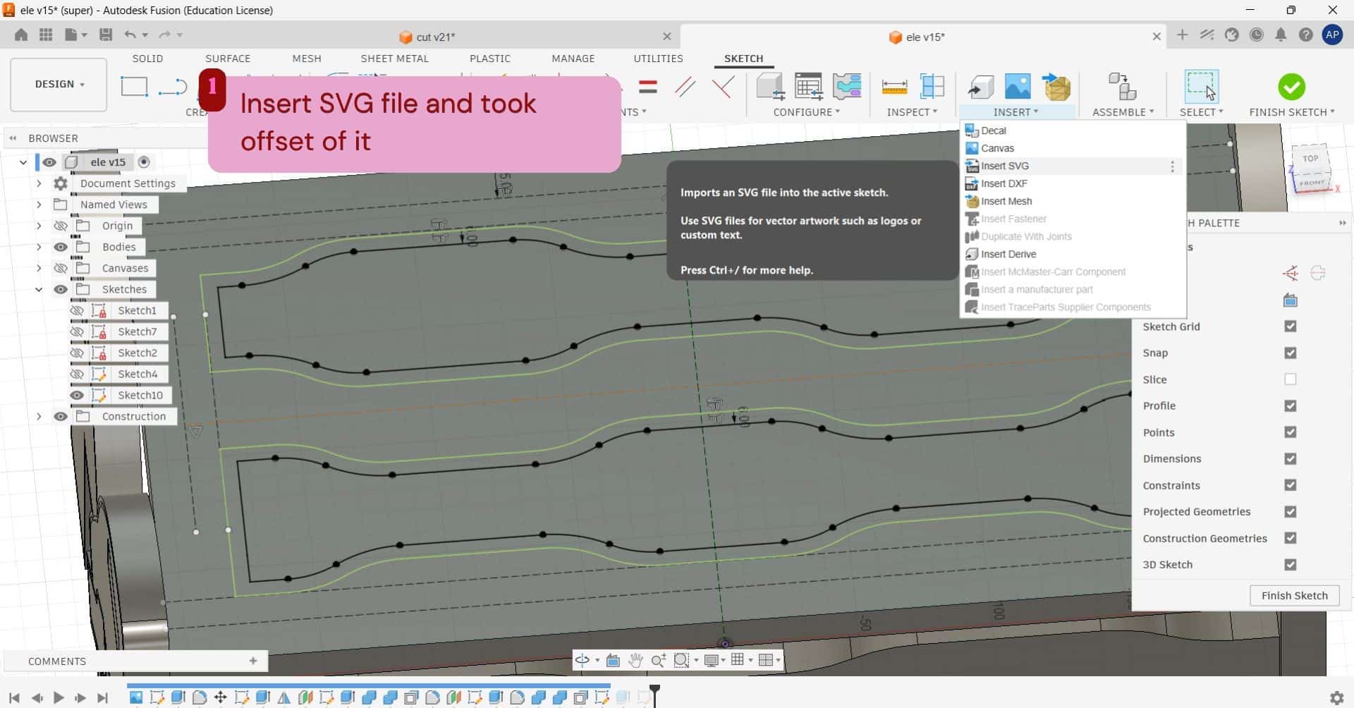
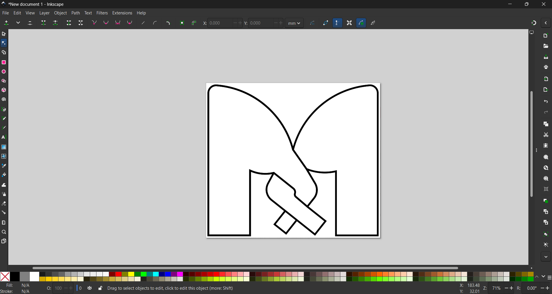
For the top plank, I wanted to create an engraved effect.
For that, I used the front plank design, first projected the sketch of the front plank using
the Project tool, then exported it as a DXF file.
I opened the DXF in Inkscape and exported it as an SVG file.
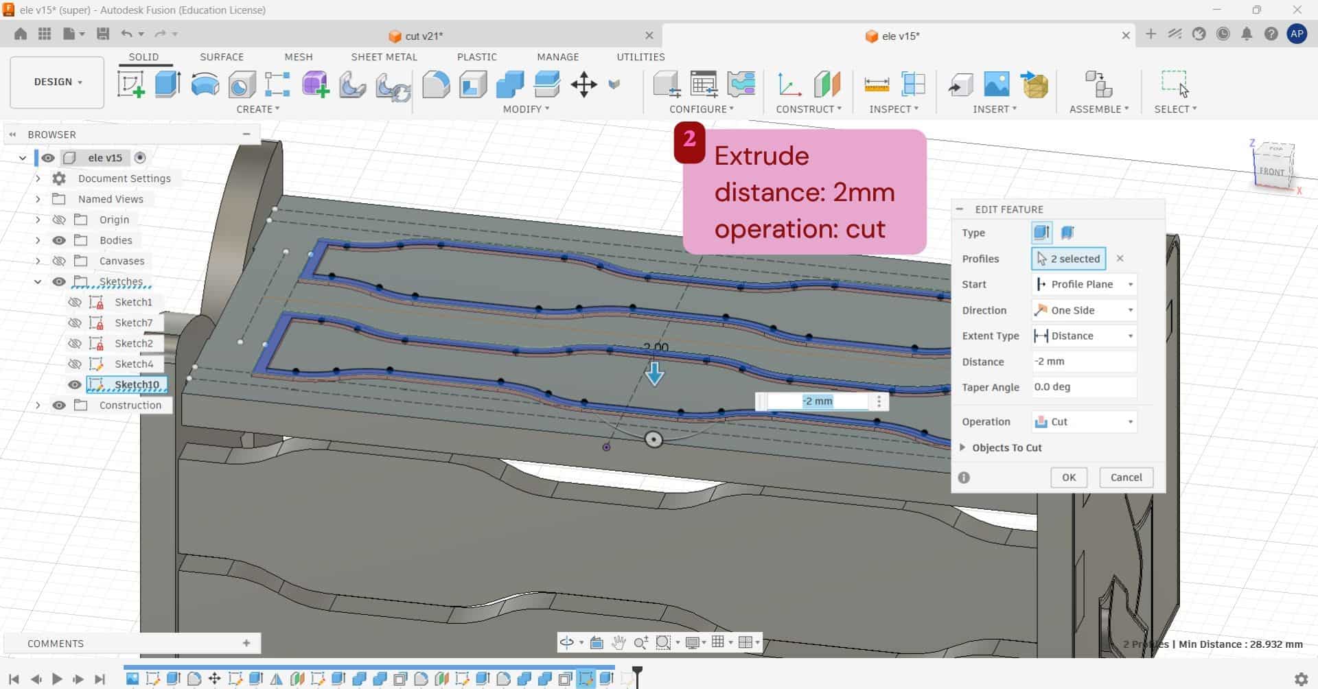
After that, I used Insert SVG in Fusion to import the design onto the top plank.
I then gave an offset to the imported design and extruded it inward using a cut operation.
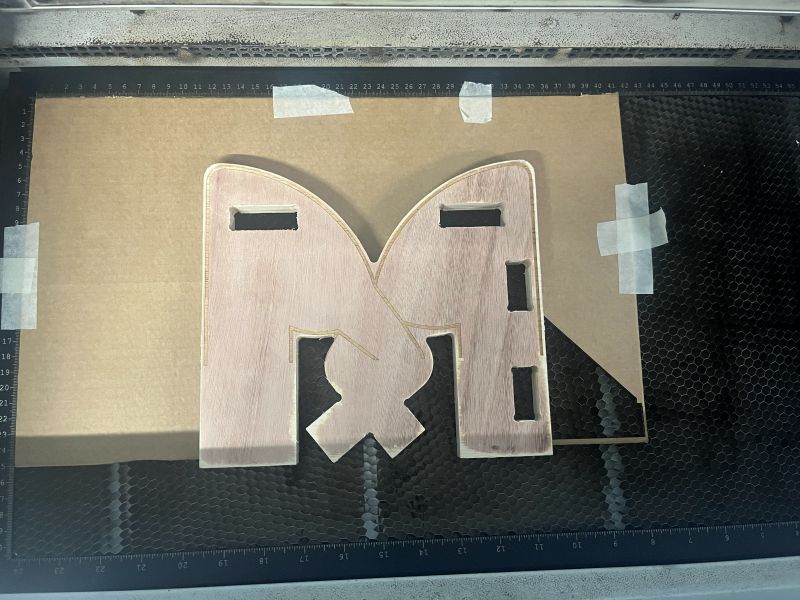
Laser cutting - joinery test
Before cutting the final plywood model on the ShopBot, tested the design using cardboard on the Trotec laser cutter. To check the fit of joints, dimensions, and overall assembly. This helped identify design errors early, saved material, reduced machining time, and prevented costly mistakes on the final plywood.
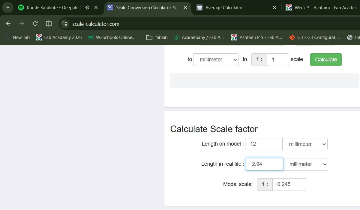
After measuring the cardboard at multiple points, I calculated an average thickness of 2.94 mm. I used this value to find the scale ratio for reducing the model from 12 mm to 2.94 mm.
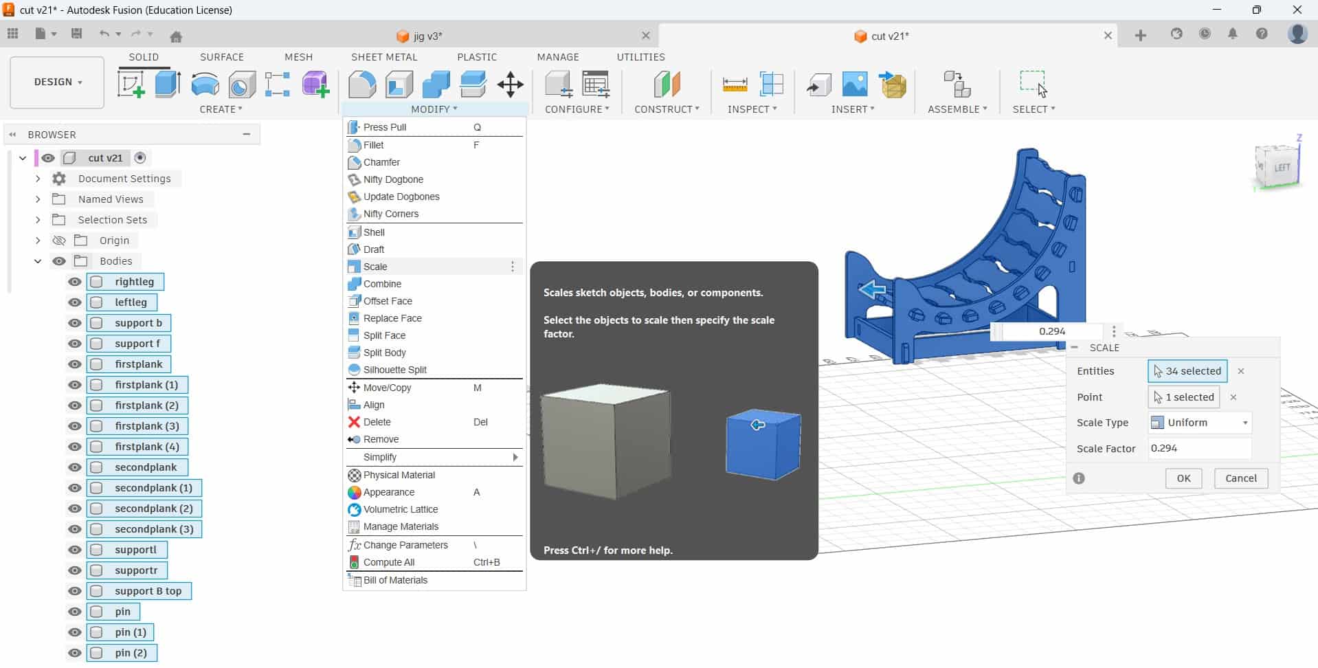
The calculated scale factor was entered into the Scale tool in Fusion 360, and the thickness parameter was then adjusted to 3 mm.
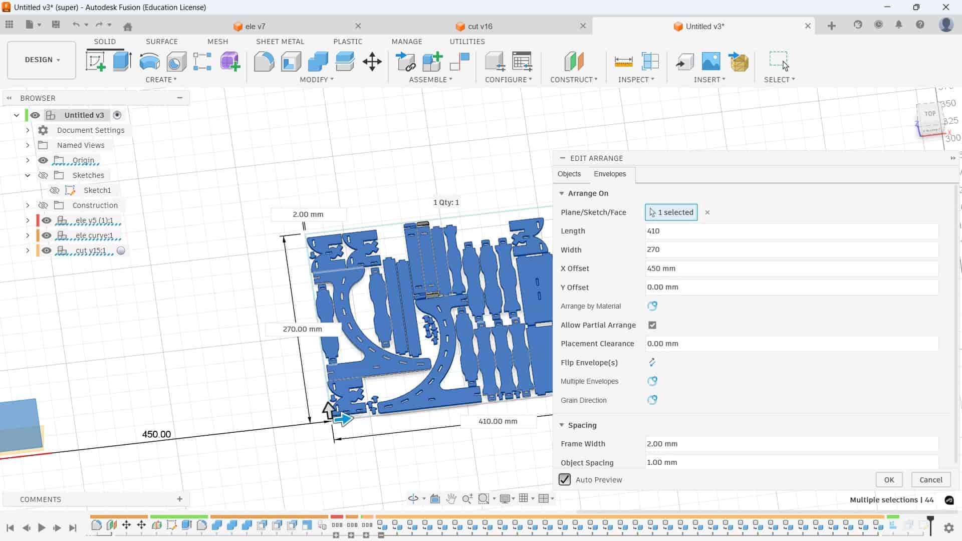
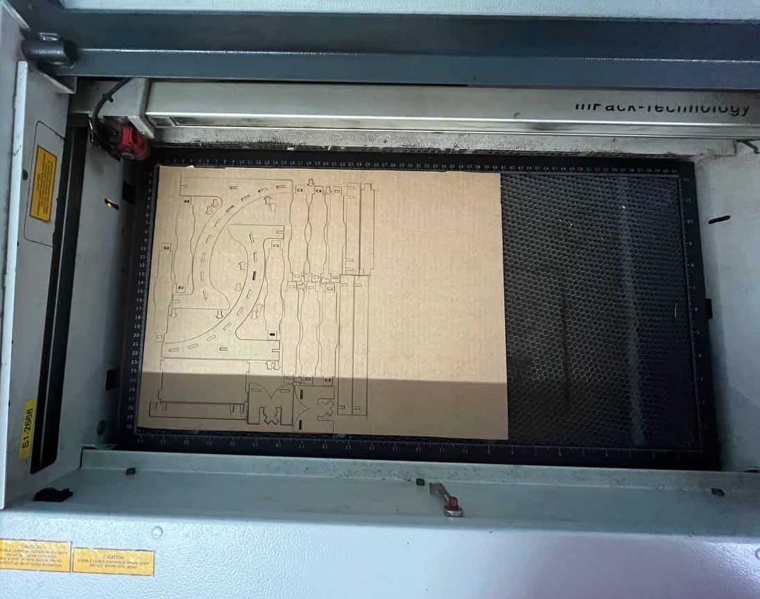
Using the Arrange feature, I arranged all the parts within the cardboard sheet size of 410 mm x 270 mm. I kept the frame width as 2 mm and the object spacing as 1 mm to place the parts efficiently. After arranging them, I laser cut the pieces using the Trotec Speedy 100.
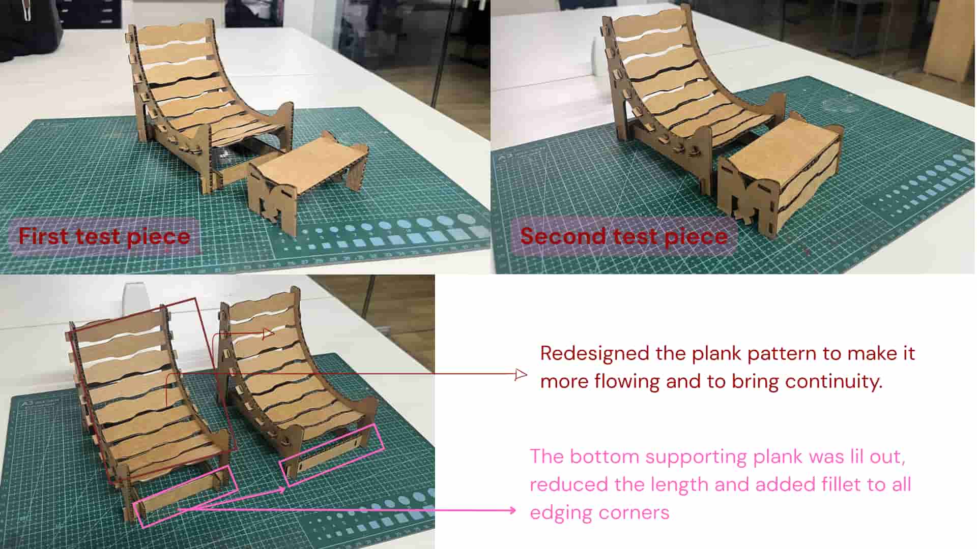
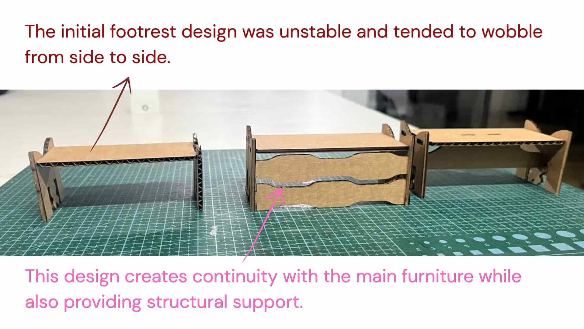
Design iteration
CAM: V- Carve
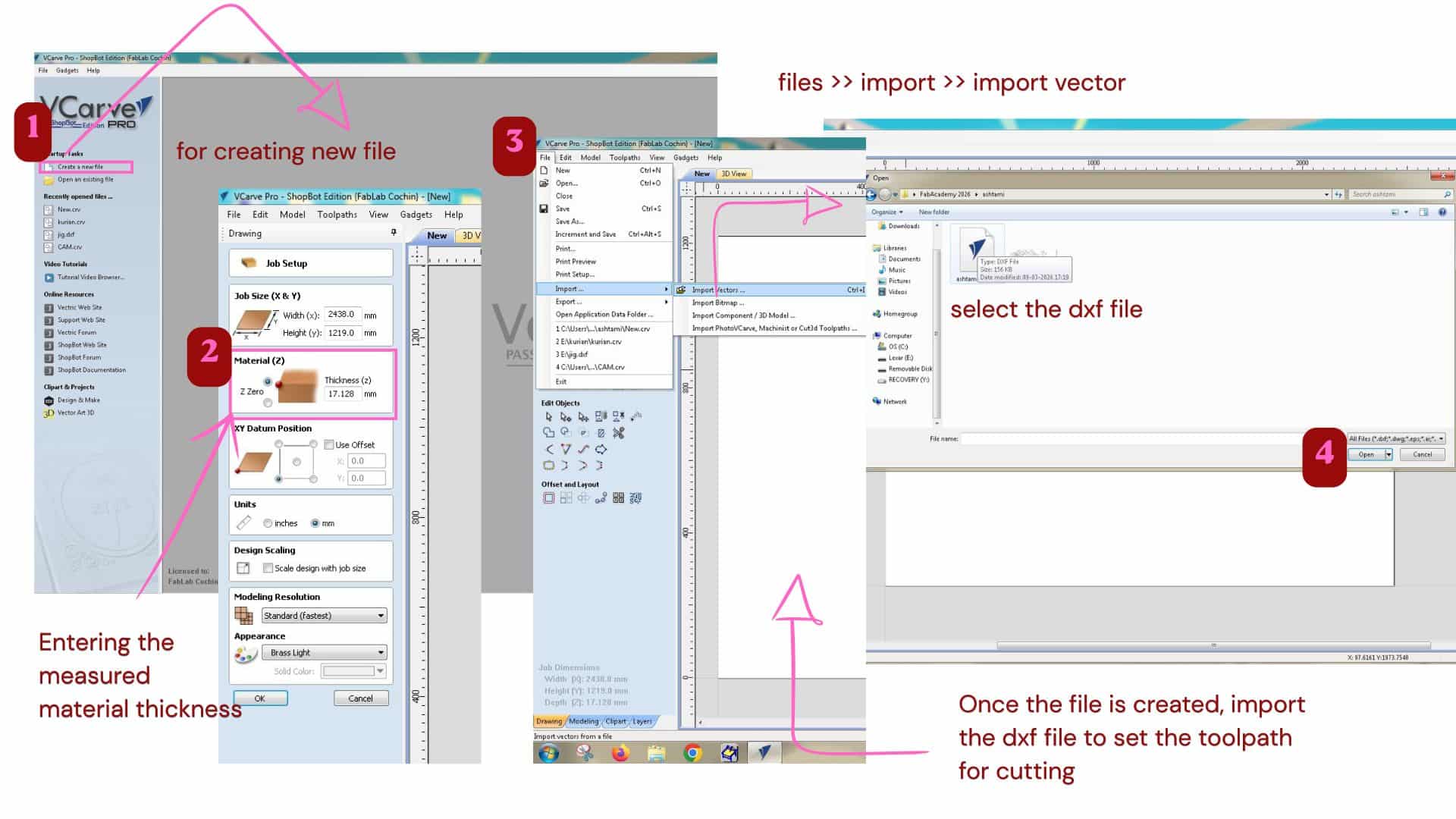
We used VCarve software to perform the CAM process and generate the toolpaths for CNC machining.
Reference_Manual:VCarvePro_V5
In VCarve, all vector sketches need to be joined and closed because toolpaths follow the vector boundaries.
For that click on each shapes, and check if it has closed pink dotted boundaries.
If not, has to join the vector using join vector tool
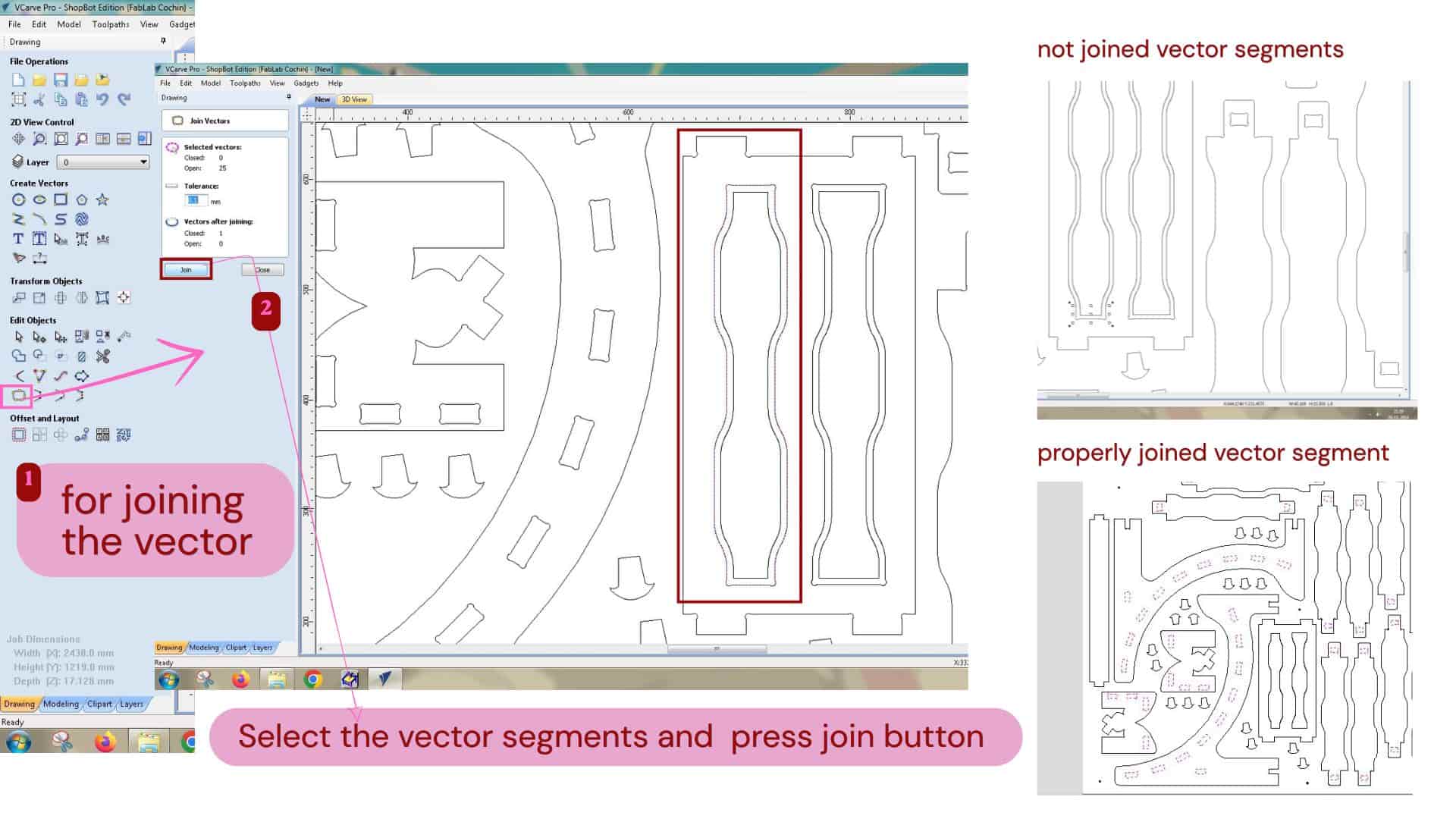
Join vector
used to join separate lines, arcs, or curves into one continuous closed shape. Combines broken or separate vector segments and closes gaps between lines.
Fixing the material to the sacrificial layer(bed) is very important before machining. If it is not secured properly, the material can move due to machine vibrations, which affects cutting accuracy and can even break the tool. It may also cause rough edges or the piece lifting during cutting. The sacrificial layer also protects the machine bed when the tool goes slightly deeper than the material.
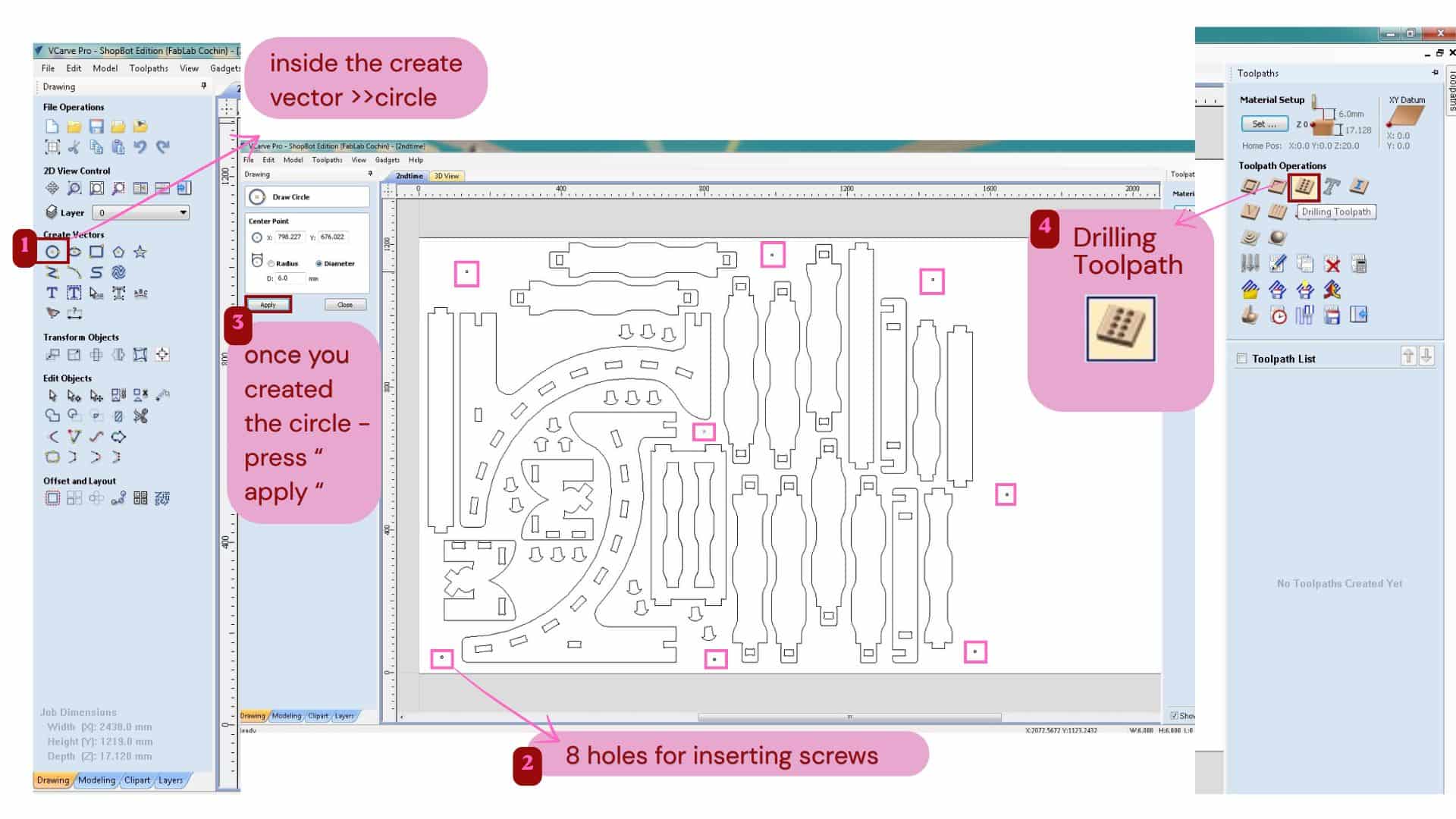
To fix the material properly, we plan the drill holes in the CAM software itself. This is safer than drilling manually because we may not know where the internal cut pieces are located, and wrong drilling can damage endmill.
Drilling toolpath
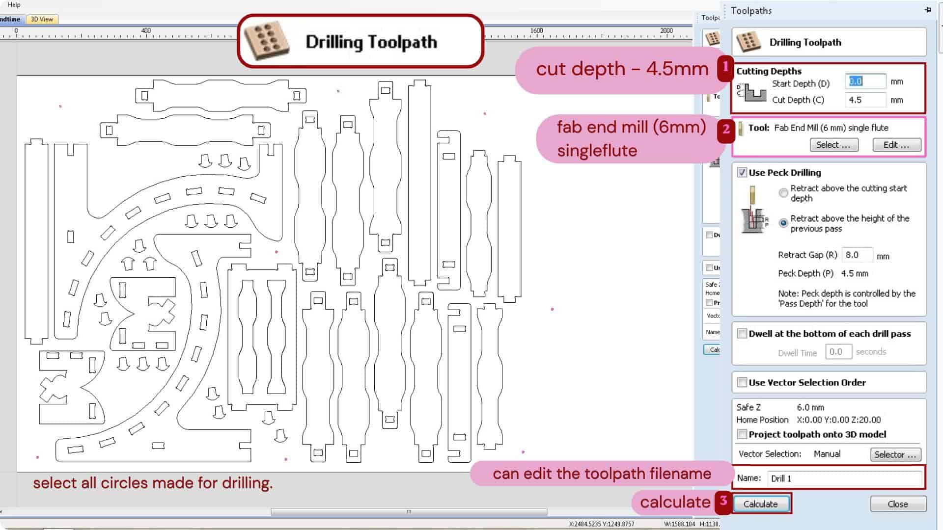
We mark circles in the file where screws are needed and generate drill paths using the Drilling toolpath with a specific cut depth. As i gave 4.5mm as cut depth
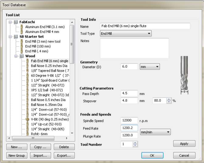
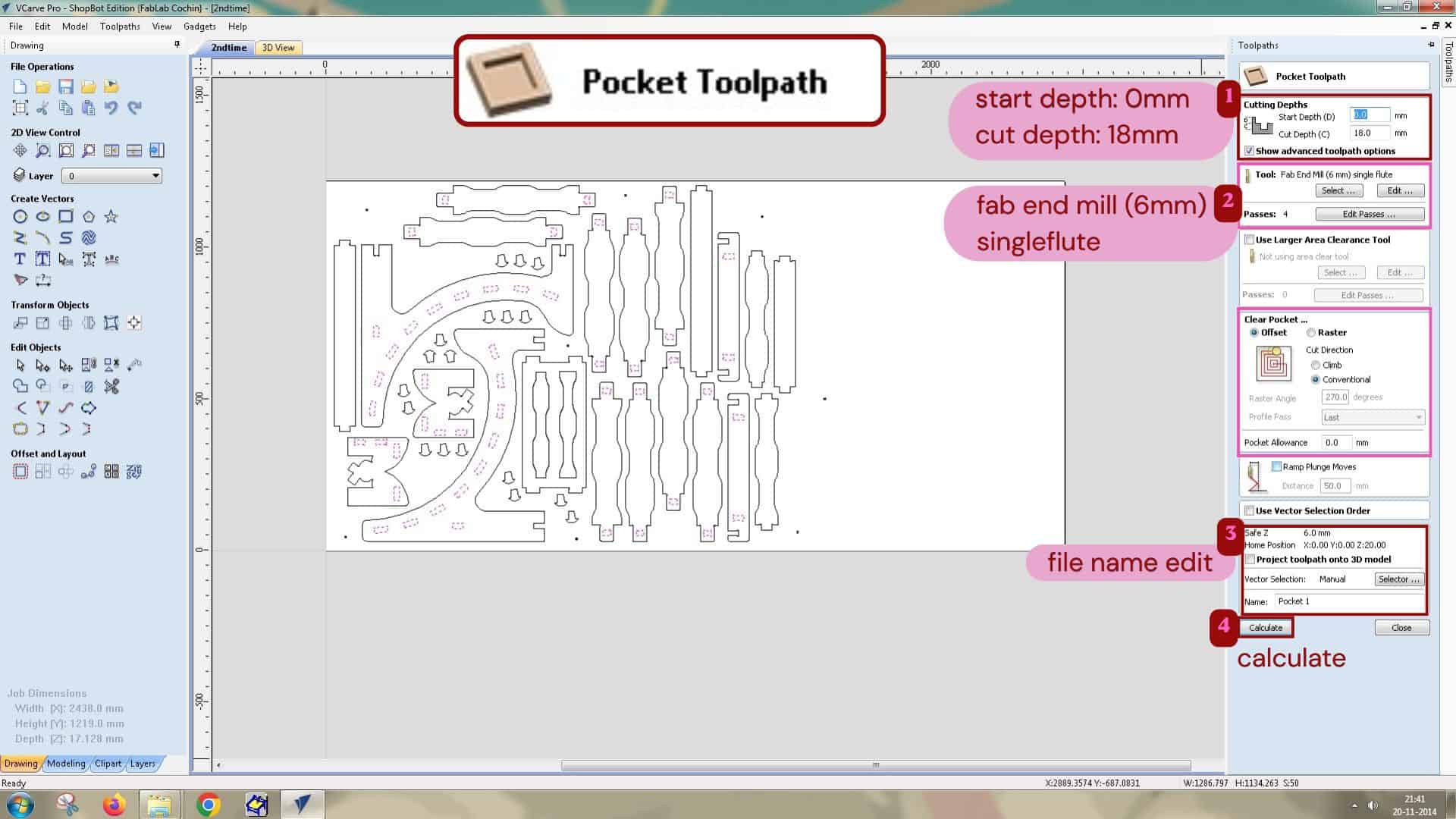
A single flute 6mm end mill tool was used, the cutting parameters were:
Pass depth
4.5mm - this is how much depth the tool cuts in one pass.
So suppose the cut depth is 18mm then for achieving it has go 4 passes.
That means 1st pass: 4.5mm, 2nd pass: 9mm, 3rd pass: 13.5mm, 4th pass: 18mm.
Step over
4.8mm - this is distance the tool moves sideways between passes.
It moves 4.8mm between one pass and the next while clearing the materials.
Feeds and Speeds
Spindle speed
12000rpm - this is the speed at which spindle/bit rotates.
Feed rate
1200.2 mm/min - this is speed at which the tool moves x and y - directions while cutting.
Plunge rate
1200.0 mm/min - this is the speed at which the tool moves downward into the material in the Z direction.
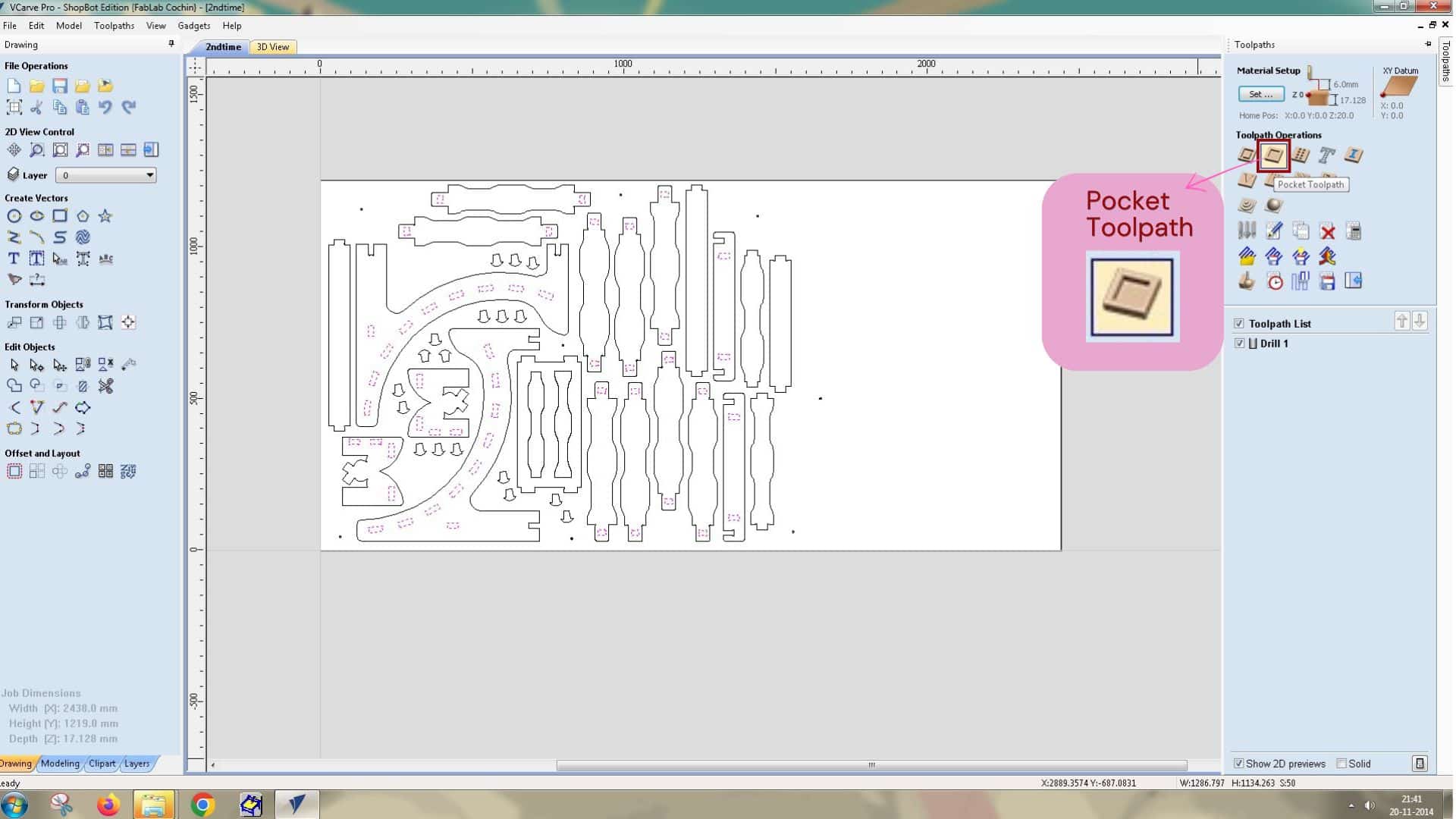
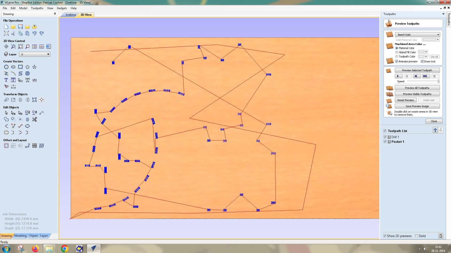
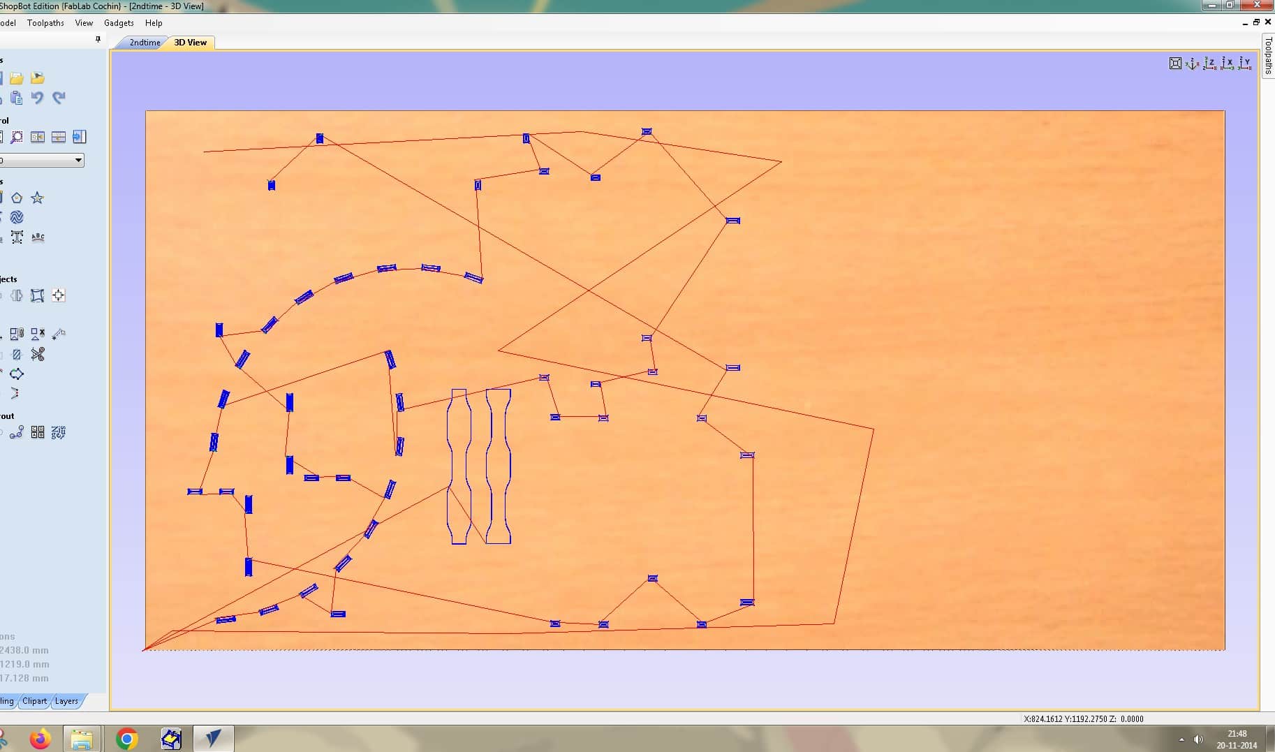
For cutting the slot inside the parts, I used a Pocket Toolpath operation,
Pocket operation
This operation is used to clears the entire inner area of the slot to the required depth.
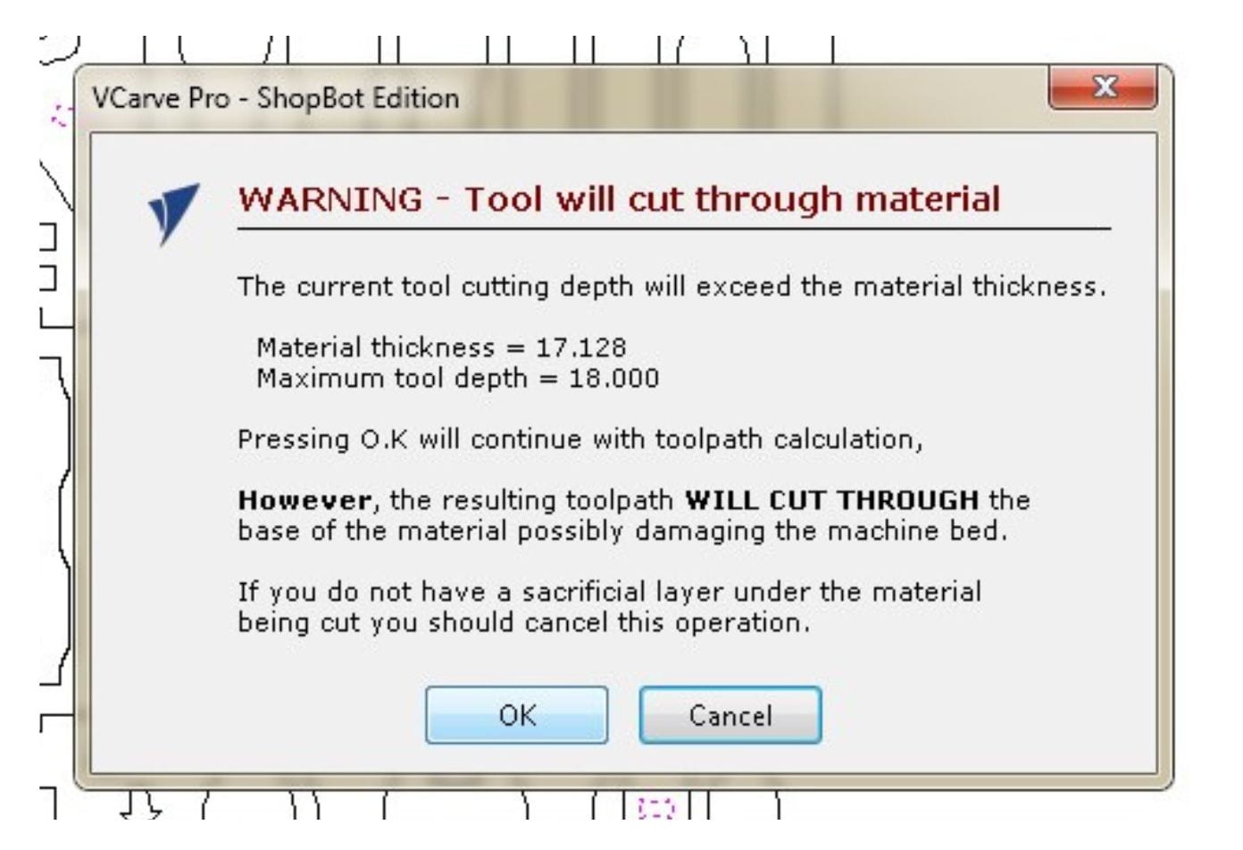
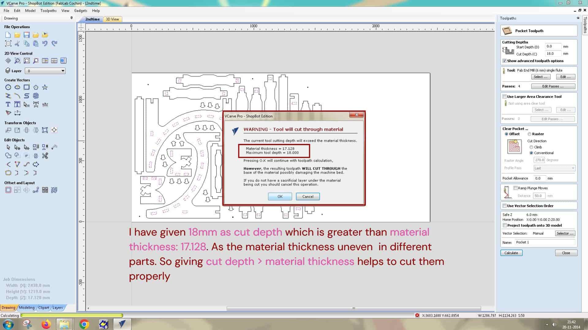
I gave 18 mm as the cut depth, which is greater than the material thickness of 17.128 mm. Since the material thickness was uneven in different parts, keeping the cut depth slightly more than the material thickness helped to cut properly them throughout.
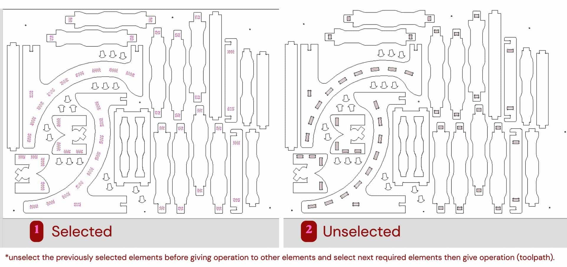
Before setting the next operation, I unselected the previously selected slot vectors and then selected the next required parts to apply the corresponding toolpath operation.
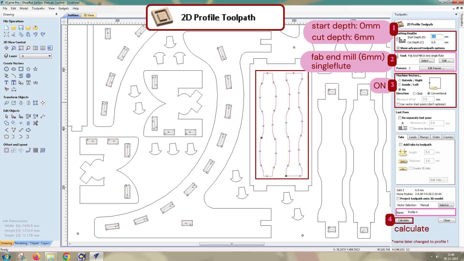
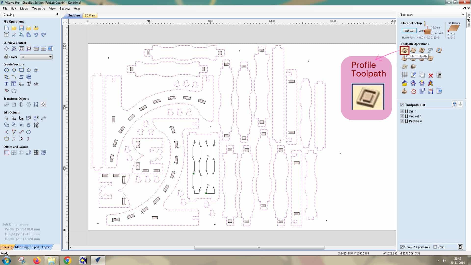
I wanted to create an engraving effect on the top surface of the footrest. For creating it, i used Profile toolpath operation:
2D Profile operation
This is used to cut along the vector lines, it doesn't clear out the whole inside area. It can cut outside, inside or on the vector lines.
I set the cut depth to 6 mm and selected Machine Vectors "On" so that the tool would cut directly on the vector.
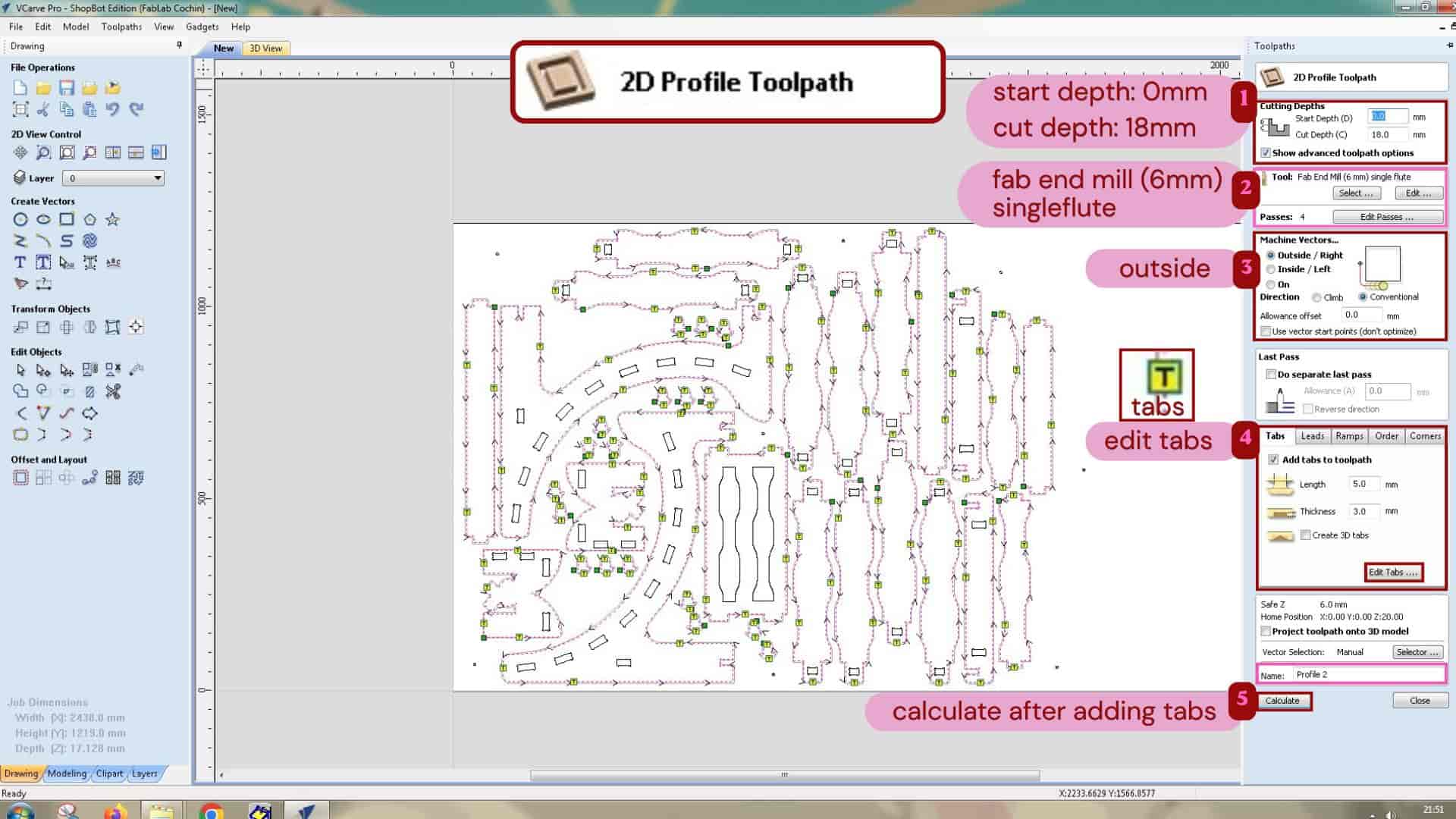
For cutting the parts out of the material, I used a 2D Profile Toolpath.
I set the cut depth to 18 mm and selected Machine Outside/right, so that the final dimensions of the parts would be maintained as designed.
I also added tabs to hold the parts in place during machining; as the machine cuts the outer profile of the parts,
if it cuts all the way through, parts can move, vibrate, shift from the its position, or get hit by the tools.
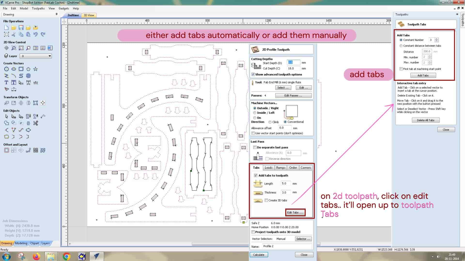
Tabs
They are the small uncut portions of material left intentionally in between the part and whole sheet to hold the part in place;
so the cut part remain attached to the material.
During the post processing, tabs can be removed manually using the chisel and mallet.
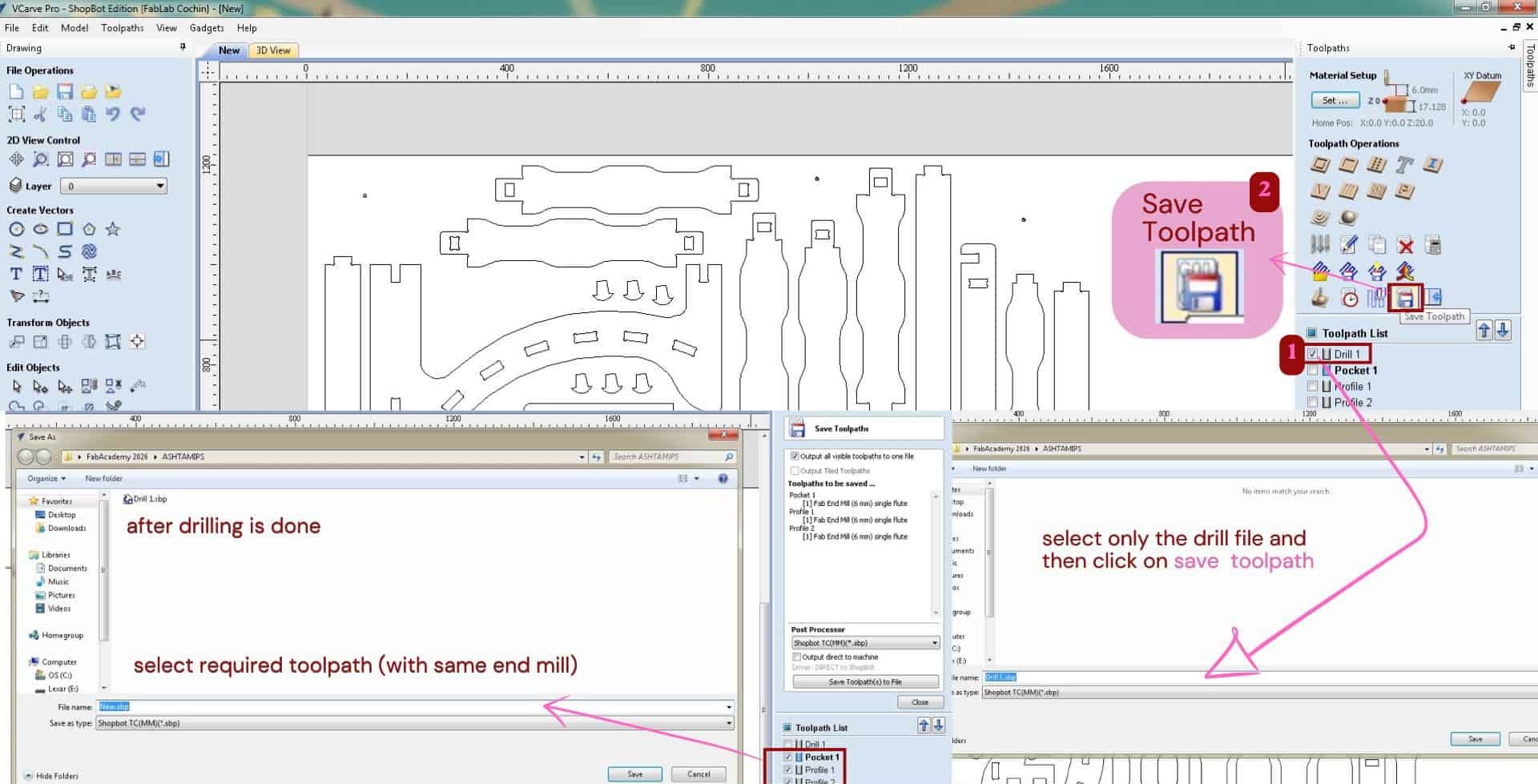
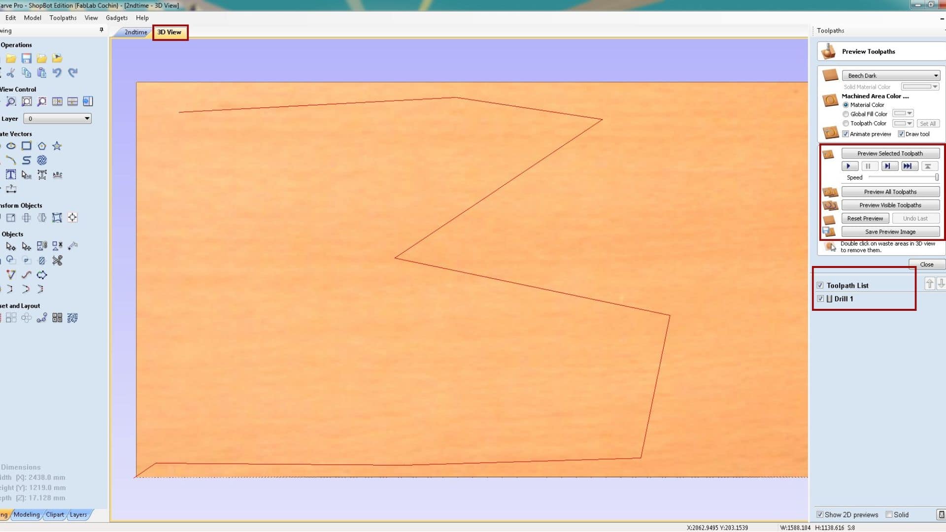
After creating the toolpaths, I used the Save Toolpath option to export them.
First, I saved only the drilling toolpath, since I have to make the drill holes first.
These holes were then used to manually drill screws and fix the material securely onto the sacrificial layer.
After that, I saved the remaining toolpaths together, as all the other operations were done using the same 6 mm tool,
and exported them with in .sbp file extension.
ShopBot: CNC milling machine.
With this machine, we can engrave and cut materials. The machine moves in three axes:
- X-axis - the longest side of the machine
- Y-axis - the shortest side
- Z-axis - the vertical movement where the tool moves up and down
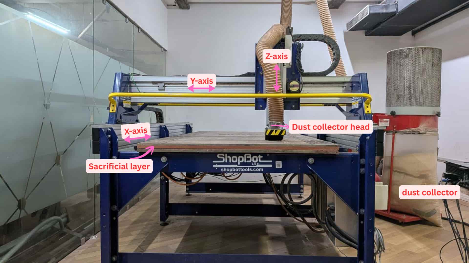
Photo credits: ALI
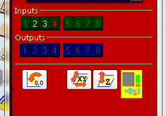
SB3 ShopBot Control Software: setting x,y,z axis and sending machining files
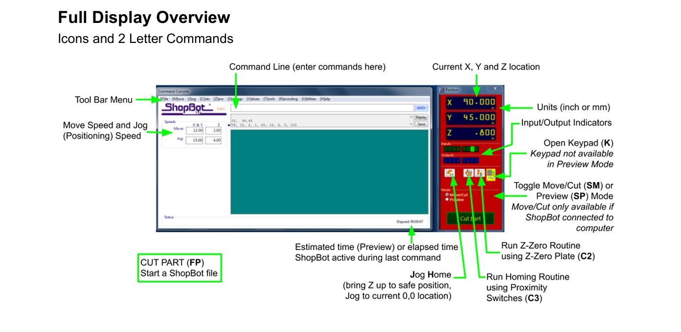
About zeroing XYZ axis and keypad

source: shopbot_Handbook2022
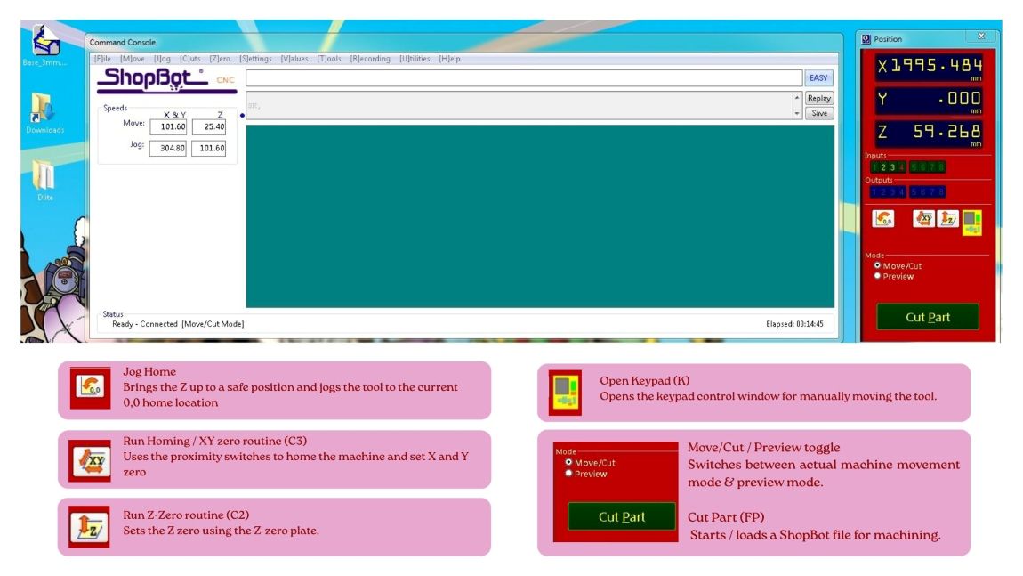
Setting X, Y and Z zero on the ShopBot
Move/Cut mode
Before zeroing the machine, make sure the ShopBot software was in Move/Cut mode and not in Preview mode, because the keypad controls and zeroing options only work in Move/Cut mode.
Homing the X and Y axes
First, I ran the C3 command to home the X and Y axes.
This makes the machine go to its home position using the proximity switches.
Set the default X and Y zero at the lower-left corner of the ShopBot bed.
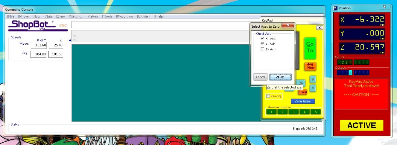
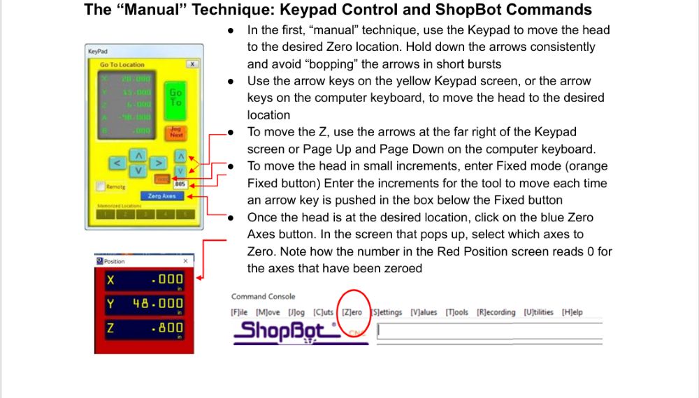
Zeroing X-Y axis
After homing the machine, I used the keypad to move the tool to the point on the plywood where I wanted to set the origin.
Once the tool reached that point, I clicked:
Zero Axes, selected X and Y, and clicked Zero.
This set that point as the new X and Y origin (0,0) for machining.
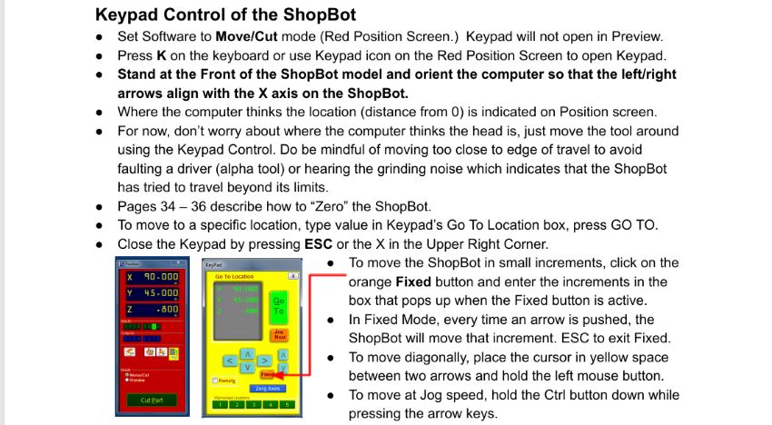
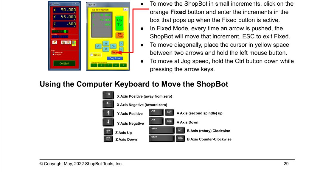
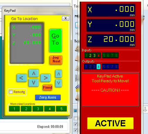
Fixed mode: in keypad
Using the Fixed mode to move the tool in small steps.
Instead of moving continuously, the spindle moves only by the increment value entered each time an arrow key is pressed.
Incase if there is no enough space for setting z axis zeroing, move x and y axis.
I took this video from Ardradevi, in this she is placing the z-zero plate on the top of material and clamping the alligator clip on the spindle for setting z-axis
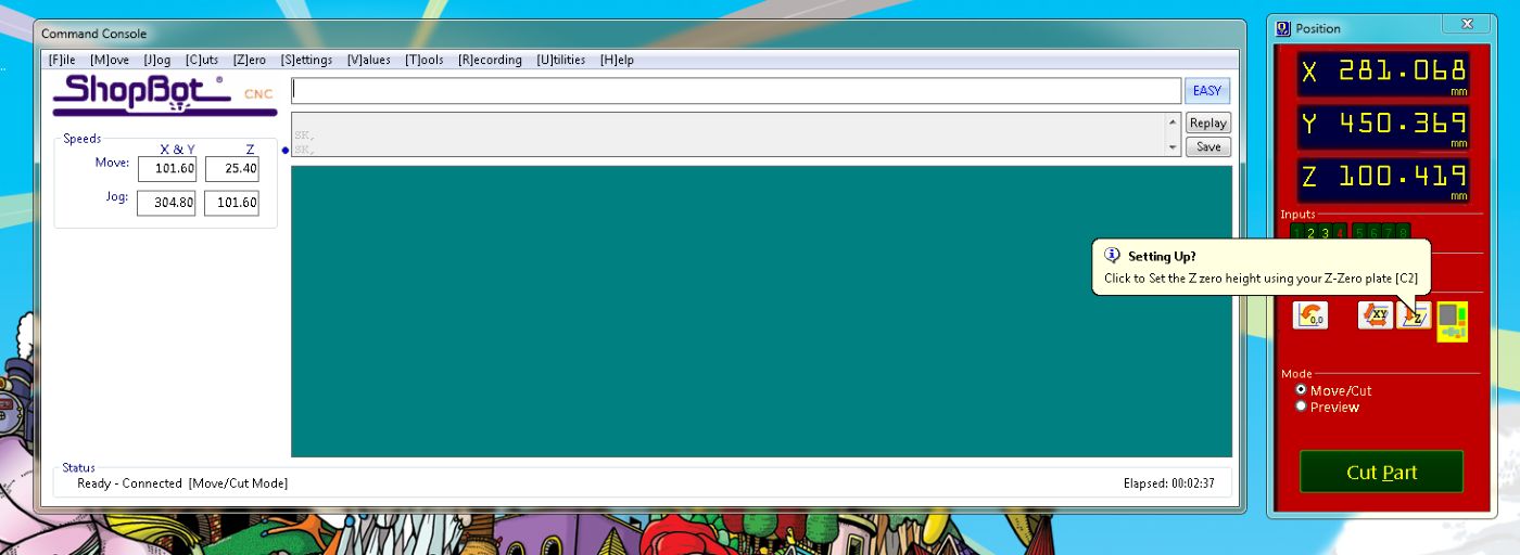
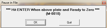
Preparing for Z zero
To set the Z zero, placed the Z-zero plate under the tool and attached the alligator clip to the spindle collet.
This completes an electrical circuit between the tool and the plate.
When the plate touched the bit, Input 1 in the ShopBot software turns on, confirming that the connection was working properly.
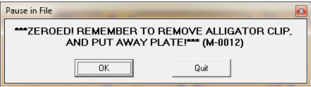
Running the Z-zero routine
After that, I ran the C2 Z-zero routine. The tool touched the plate twice, and automatically set the Z origin before moving back up.
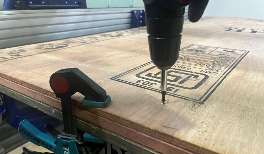
Sending the drill file
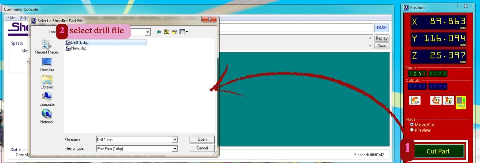
click on cutpart and open the file location, then select drill1.sbp
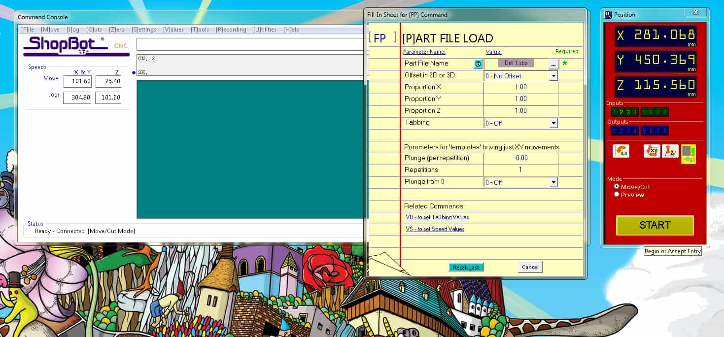
Click the start button on software
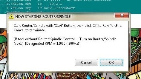
Read the dialog box showed up, it says for starting spindle: press the start button on hardware, then click ok to run partfile.
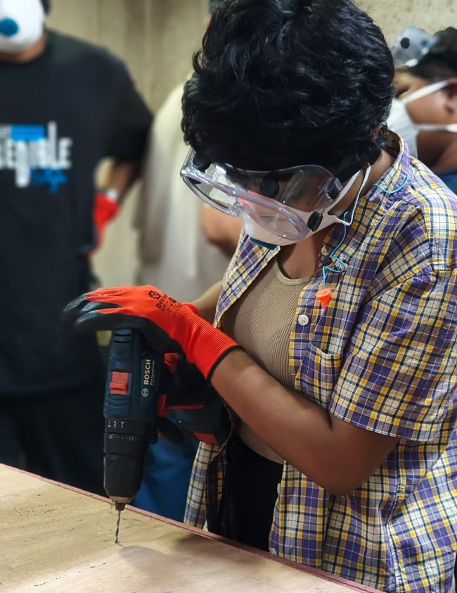
After making drill holes, manually drilled the screws into the material to securely hold to sacrificial layer
Sending cut file
Next send "New.sbp", which had the rest of operations. I think to run this partfile, it took me more than 2 hours.
Issues faced
Some of the cut pieces came loose during machining because the tabs did not hold them properly. I paused the job by pressing the spacebar to stop the machine, then removed the loose pieces to prevent them from hitting the bit and damaging the tool. After taking it out, resumed the machining. I also noticed that the plywood sheet was not completely flat, which may have affected the cutting.
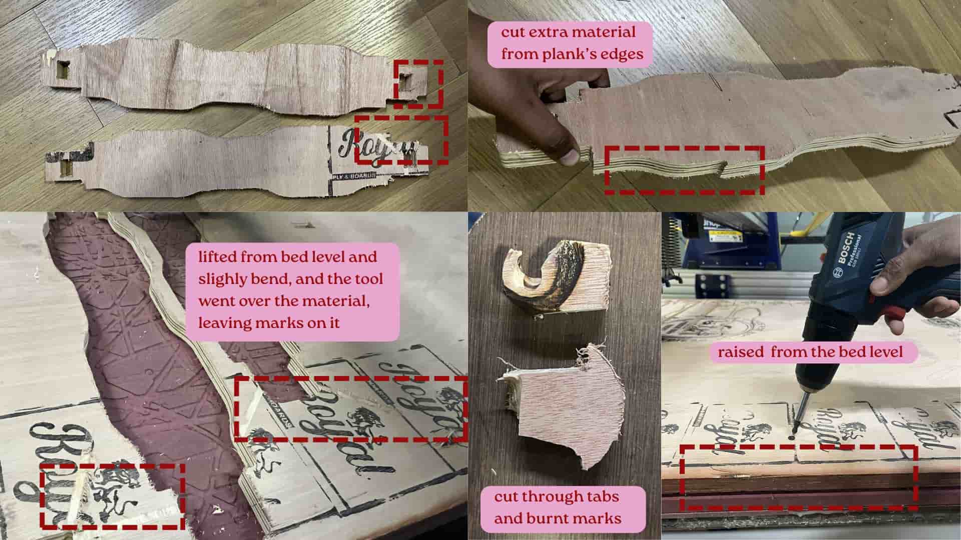
Some areas of the plywood were not screwed down properly to the sacrificial layer,
so the sheet lifted slightly from the bed.
Because of this, the cutting depth became uneven, z- axis depth isn't consistent.
In some places, the tool cut through the tabs, and while machining the tool went over the material slightly and we can see the tool bit markings.
After unscrewing and again screwing the material to bed.
I tried cutting the damaged front plank pieces again after finishing previous partfile, but the slight bending of
the plywood and bed-leveling issues still affected the result.
Not all the pins failed — only the ones in the areas where the
plywood was not laying flat on the bed and one pin had burn marks.
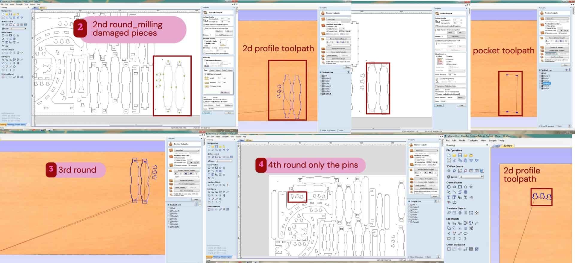
After adjusting and recutting, the 2 damaged planks came out correctly on the third attempt and 3 pins on fourth attempt.
Post processing
Source: week7 group assignment
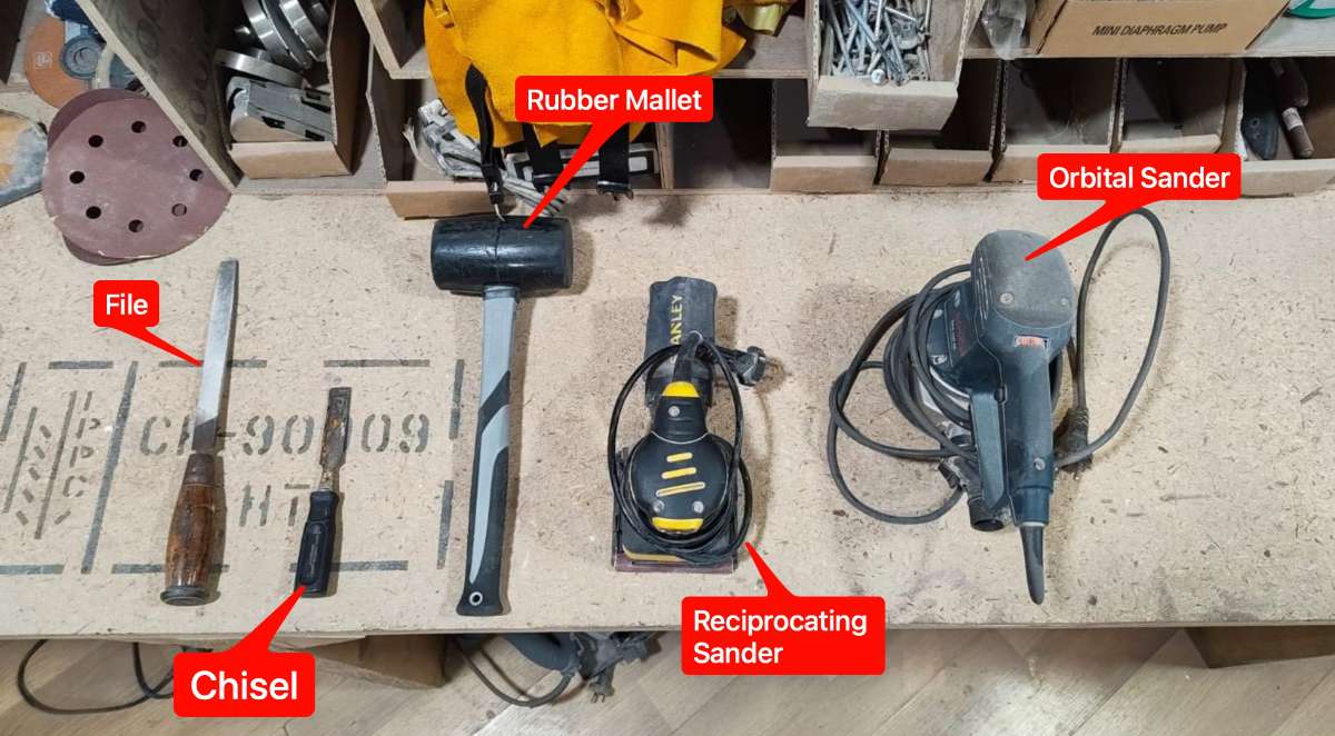
These were the tools used for post processing.
The next day, I did the post-processing. First, I removed the cut pieces from the plywood sheet by cutting the tabs using a chisel and mallet.
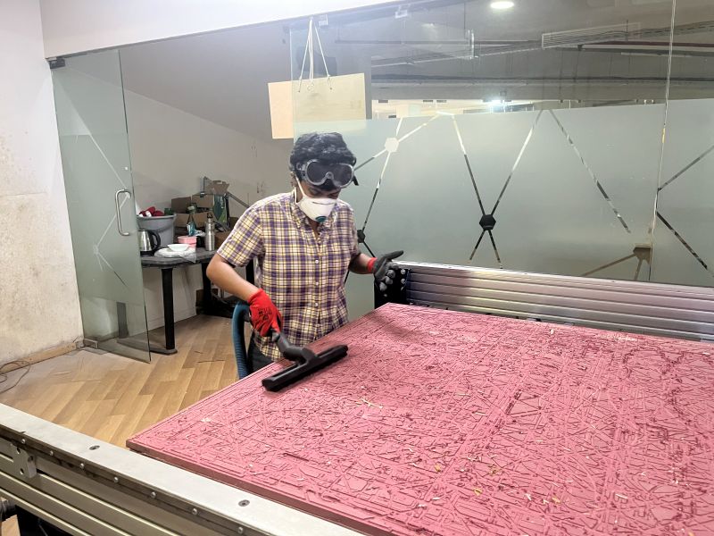
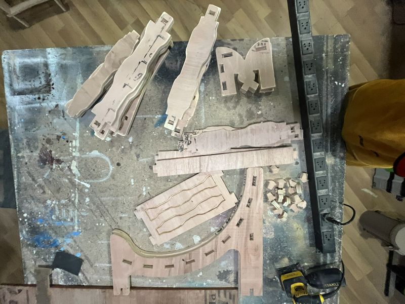
After taking out all the parts, I removed the remaining material from the machine bed and cleaned the bed using a vacuum cleaner.
I used an orbital sander to smooth the surfaces and edges of the cut pieces. Then, I used a chisel to remove the remaining tab marks and clean up the edges before assembly.
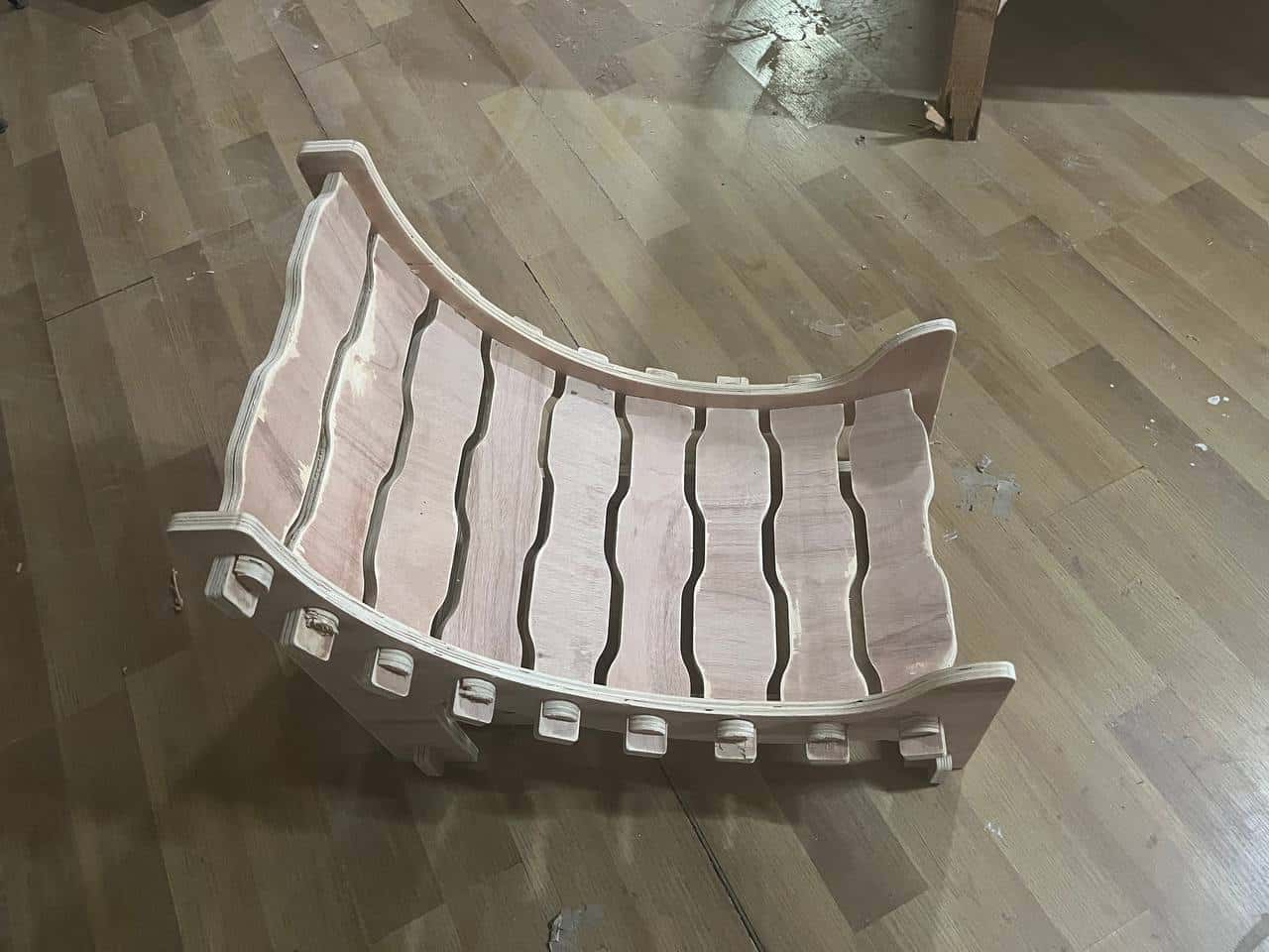
Assembly
I started assembling the cut parts by fitting the planks into the one side legs and then other leg inserted.
As several planks had to be inserted and aligned at the same time, the assembly process was a little difficult.
The joints were quite tight, so I used a file to smooth the edges of the joints before fitting them together.
Using a rubber mallet to gently tap the pieces into place or it might crack.
Some of the pins were too tight and needed additional filing before they could fit properly.
During assembly, a few pin edges got small cracks.
Anyways, with my instructors help assembled everything well.
Future improvement:
For the next version, I would increase the joint offset (clearance) slightly. As there are multiple pins holding the planks to the side legs, a little more clearance would make the assembly much easier without affecting the overall strength of the structure.
Engraving with Trotec Speedy 100
To engrave the footrest side legs, I used the Trotec Speedy laser cutter. I imported the SVG file and first cut a stencil in cardboard of the outer shape of the footrest leg. This stencil helped me place the wooden piece in the correct position for engraving.
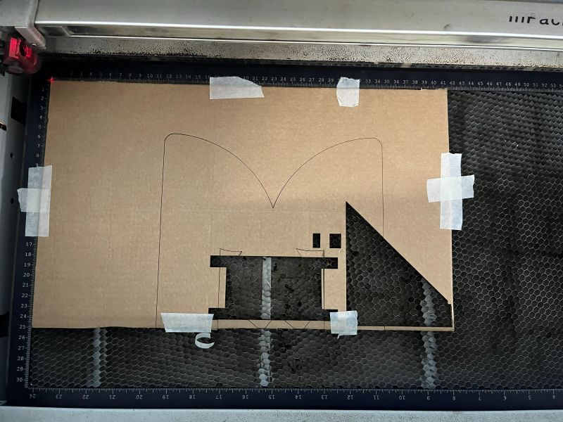
After engraving the first leg, I realized that I had forgotten to flip the SVG file for the second leg.
Because of this, I had to engrave both legs again. After correcting the design, the engraving came out well, and I assembled the footrest.