Group Assignment:
We learnt about different toolchains of different microcontrollers from different computer architectures. Along with that we compared our results to Rasberry Pi also, which is a full fledged computer rather than a microcontroller.
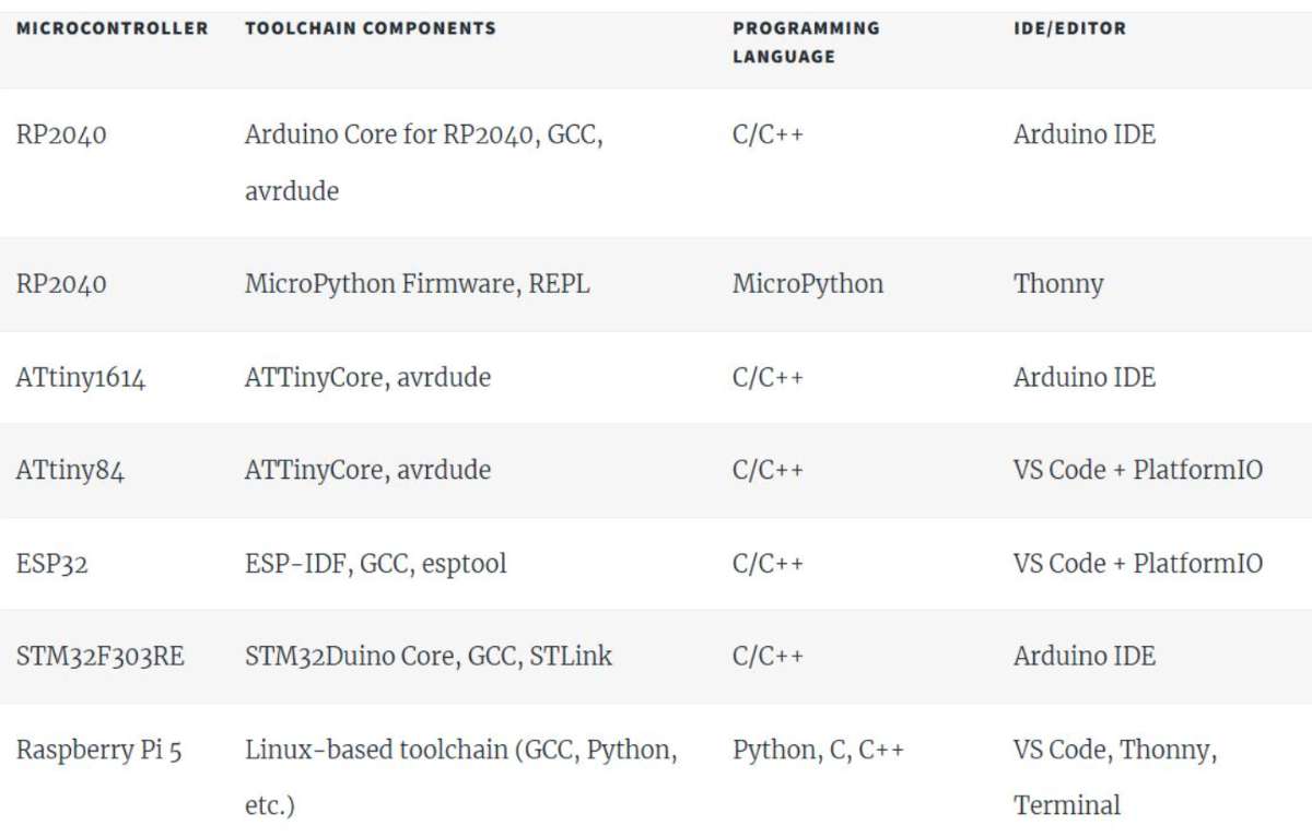 Here is the link for the group assignment:click here
This week we explored XIAO RP2040 microcontroller by first inspecting it's datasheet and programming and simulating
it via Arduino IDE.
Individual Assignment:
XIAO RP2040
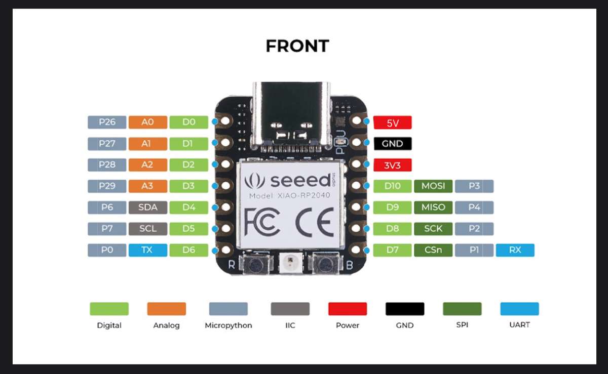
XIAO RP2040is a tiny microcontroller board made by Seeed Studio, using the RP2040 chip (from Raspberry Pi).It features a dual-core ARM Cortex-M0+ processor running up to 133 MHz, 2 MB of flash memory, and 264 KB of SRAM. The board includes 11 GPIO pins that support digital input/output, analog input (ADC), PWM, I2C, SPI, and UART communication.
The board provides 11 GPIO pins that support multiple communication and control interfaces, including:
Digital input and output
Analog input (ADC)
PWM (Pulse Width Modulation)
I2C communication
SPI communication
UART communication
The board uses a USB-C connector for programming and power supply. Due to its compact size and versatile features, it is well suited for embedded systems, Internet of Things (IoT) devices, robotics applications, and wearable electronics. The XIAO RP2040 can be programmed using Arduino, MicroPython, CircuitPython, or C/C++.
 The RP2040 microcontroller is designed by Raspberry Pi and is used in many development boards including the XIAO RP2040.
Key Specifications
Dual-core ARM Cortex-M0+ processor
Clock speed up to 133 MHz
264 KB SRAM
No internal flash (uses external memory)
USB 1.1 support
Programmable I/O (PIO)
Pinout: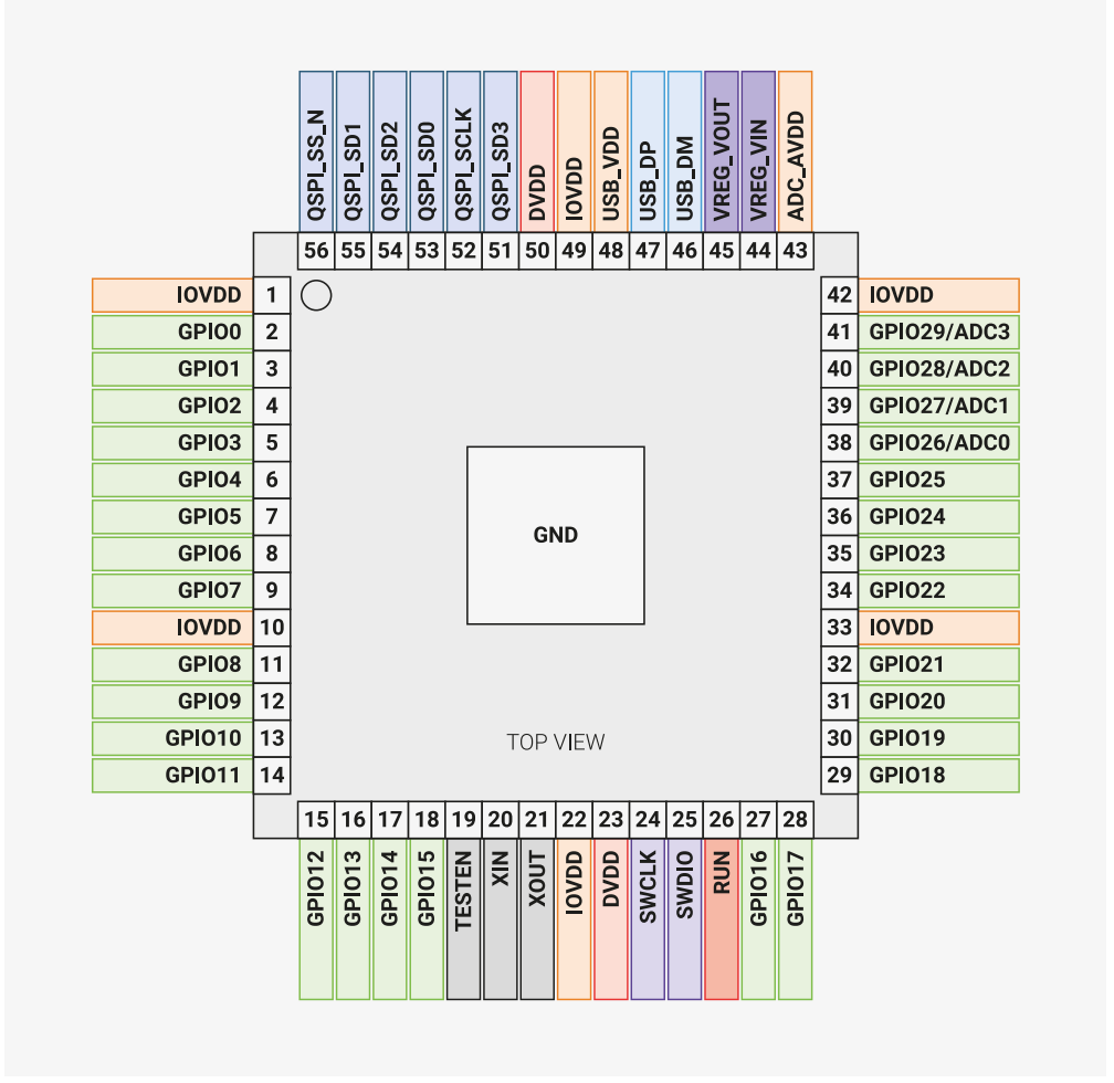 (img-Raspberry Pi RP2040 Datasheet)
 (Image Source)
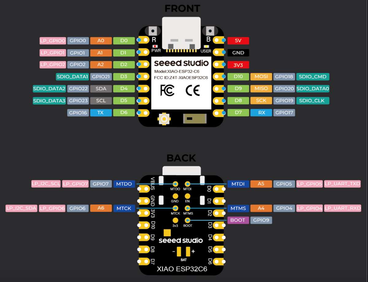
XIAO ESP32-C6
ESP32-C6 is a low-power microcontroller developed by Espressif that includes built-in Wi-Fi and Bluetooth connectivity. It uses a 32-bit RISC-V processor and is designed for wireless applications such as IoT devices, smart home systems, and robotics. The XIAO ESP32-C6 is a low-power microcontroller developed by Espressif that includes built-in Wi-Fi and Bluetooth connectivity. It uses a 32-bit RISC-V processor and is specifically designed for wireless applications.
This microcontroller is suitable for applications such as:
IoT systems
Smart home devices
Robotics
The ESP32-C6 can connect directly to the internet and control external components such as sensors, motors, and LEDs. It can also communicate with web servers and cloud platforms without requiring a wired connection. It supports GPIO, ADC, PWM, SPI, I2C, UART, and USB interfaces, making it ideal for fully wireless embedded systems like a desktop companion robot.
XIAO ESP32C6 Pin List
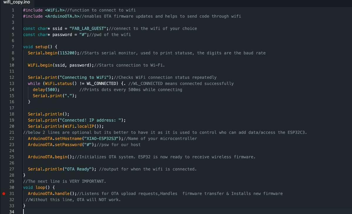
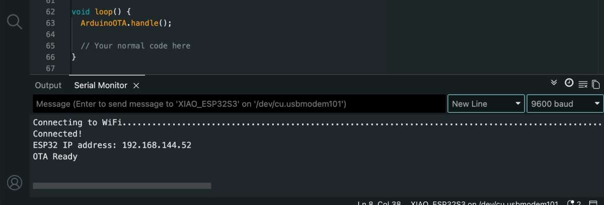
The Arduino IDE is used to write, compile, and upload programs to microcontrollers. To learn about the arduino basic function, check out this Website.
Go to - Arduino
to install and follow the given steps:
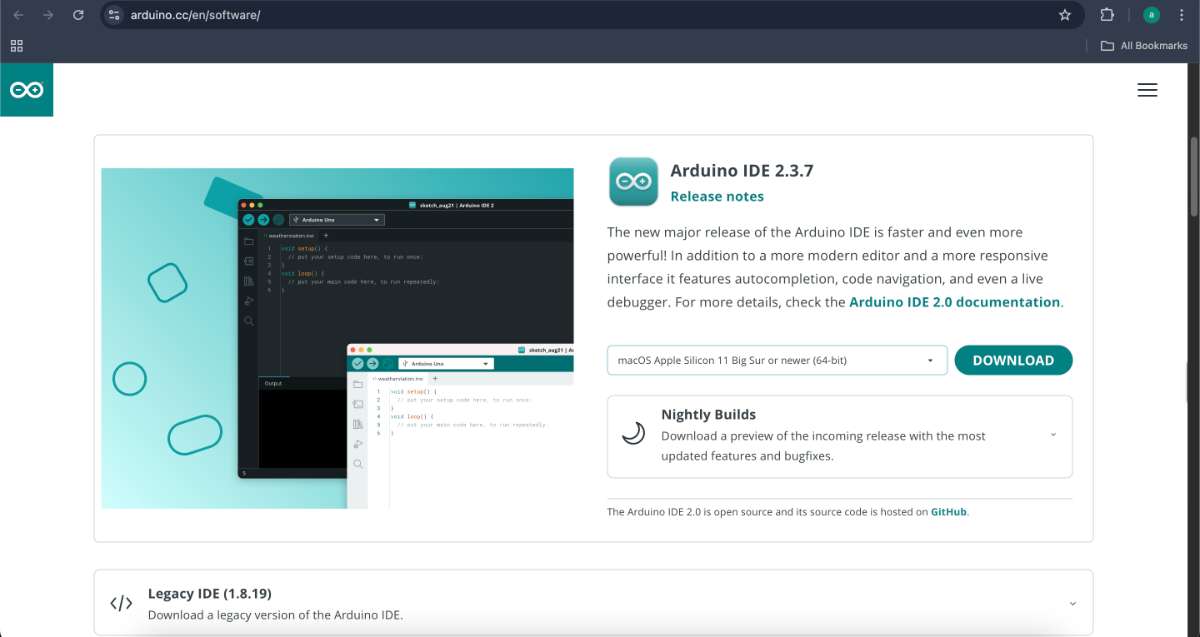
Downloaded and installed the Arduino IDE from the official Arduino website.
 Installing XIAO RP2040 Support in Arduino
By default, Arduino does not support the XIAO RP2040 board. To program the XIAO RP2040, you need to install the board support package in Arduino.
Installing XIAO RP2040 Support in Arduino
By default, Arduino does not support the XIAO RP2040 board. To program the XIAO RP2040, you need to install the board support package in Arduino.
Steps to Install XIAO RP2040 Board Support:
Open ArduinoIDE
Go to File → Preferences (Arduino → Settings on Mac)
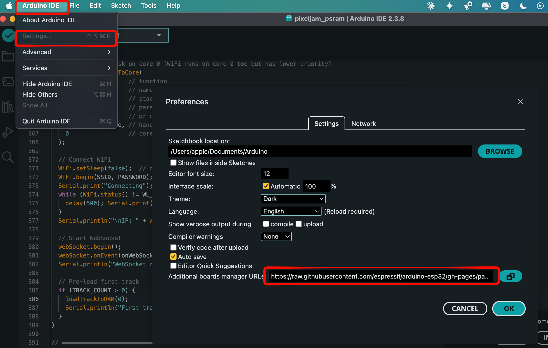 In the "Additional Boards Manager URLs" field, add:
https://github.com/earlephilhower/arduino-pico/releases/download/global/package_rp2040_index.json
Click OK
Go to Boards Manager (Tools → Board → Boards Manager)
Search for "Raspberry Pi Pico"
Install the "Raspberry Pi Pico/RP2040" board package
Follow the same format to install the XIAO ESP32C6 board support package, only difference is add the following to the board manager:
https://raw.githubusercontent.com/espressif/arduino-esp32/gh-pages/package_esp32_index.json
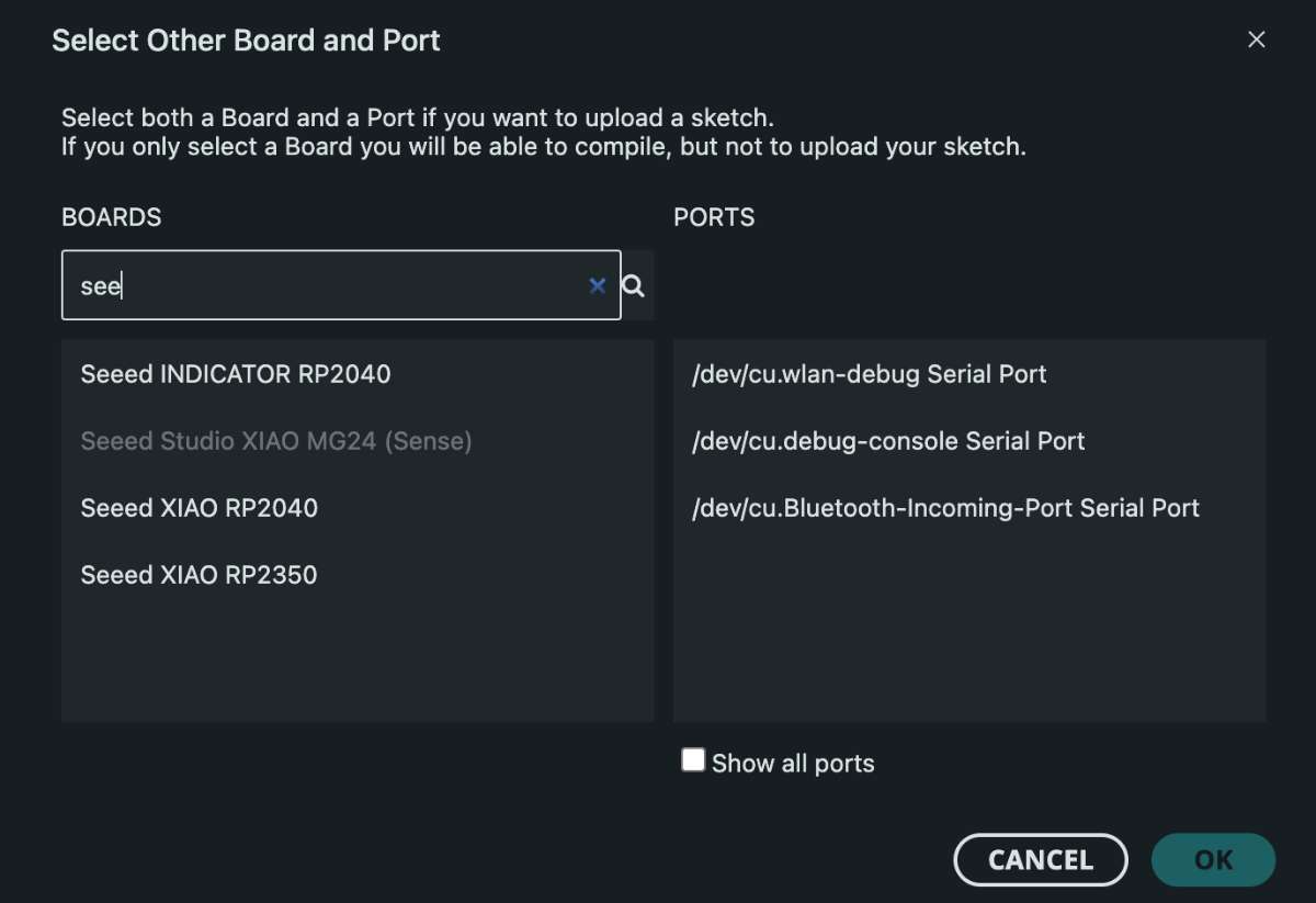
Go to "select board" panel on top of the page
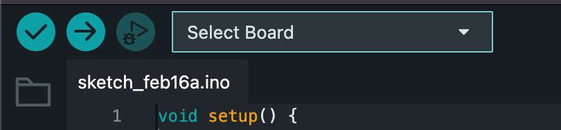
select the board of your choice
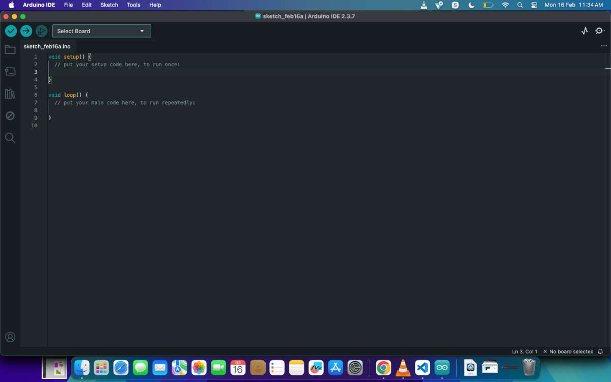
After completing these steps, the Arduino IDE was ready for programming.
I have listed some definitions for some terms used in programming:
Function: A block of code that performs a specific task and reused at different parts of the code, eg: sleep in Micropython
Class: A 'blueprint' for creating objects, eg: Pin in Micropython
Object: A specific implementation of the class, with variables containing data specific to that object
Module: A file containing multiple Python functions, classes, and variables. eg: machine
Loop: A loop is used to repeatedly execute a block of code until a specified condition is met.
Example:
while True: in Python
void loop() in Arduino
If no condition is specified, the loop runs indefinitely (infinite loop).
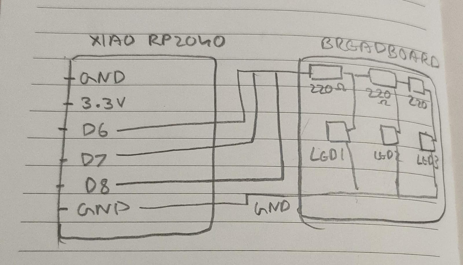
Breadboard Components Introduction
A breadboard is a fundamental tool for prototyping electronic circuits. It allows you to build circuits without soldering, making it ideal for testing and experimentation.
Breadboard Components:
Breadboard: A plastic board with holes connected by metal strips on the inside, allowing components to be inserted and connected.
LEDs (Light Emitting Diodes): Semiconductor devices that emit light when current flows through them. They have a positive (long leg - anode) and negative (short leg - cathode) side.
Resistors: Components that limit current flow. For LEDs, a current-limiting resistor (typically 220Ω or 330Ω) is used to prevent damage.
Jumper Wires: Wires with connectors on both ends used to connect components on the breadboard.
Push Button (Switch): A mechanical switch that opens or closes a circuit when pressed, commonly used for user input.
Power Supply: Usually connected to the breadboard's power rails (positive and ground/negative).
All three breadboard experiments in this documentation use these basic components in different configurations to control LEDs and other outputs.
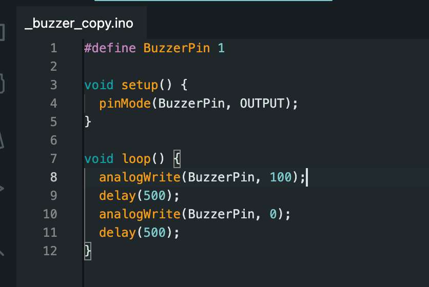
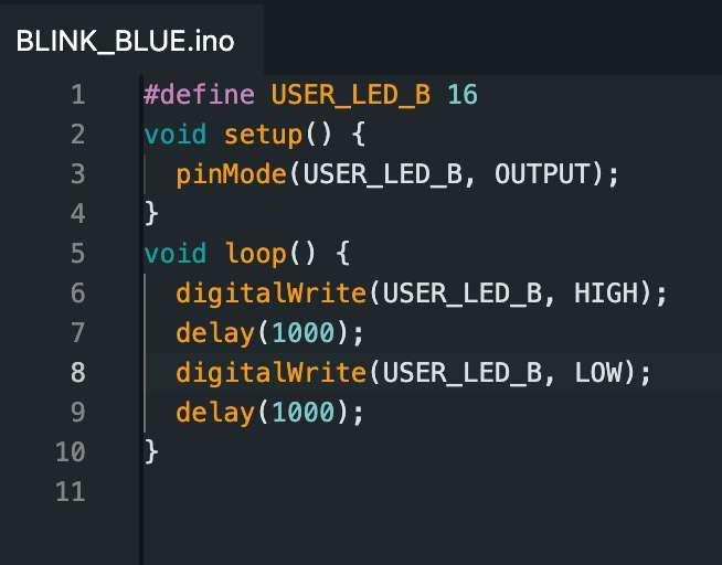
Program 1: Controlling an external LED
Language: C/C++
Microcontroller: RP2040
Board: Rasberry Pi Pico
Environment: ARDUINO IDE
click here to copy code
#define creates a constant named USER_LED_G.
It assigns the value 16, which is the GPIO pin number where the LED is connected.
This makes the code easier to read and modify.
setup() runs only once when:
- The board is powered on, or
- The reset button is pressed.
pinMode() sets the pin mode.
OUTPUT → sets pin 16 as an output pin.
loop() runs continuously forever. This is where the main program runs repeatedly.
digitalWrite() sends voltage to the pin.
HIGH means ON (3.3V)
delay pauses the program.
1000 milliseconds = 1 second
Language: C/C++
Microcontroller: RP2040
Board: Rasberry Pi Pico
Environment: ARDUINO IDE
Following is the commented code for the program:
click here to copy code
Program 3: Controlling an LED using button
Language: C/C++
Microcontroller: RP2040
Board: Rasberry Pi Pico
Environment: ARDUINO IDE
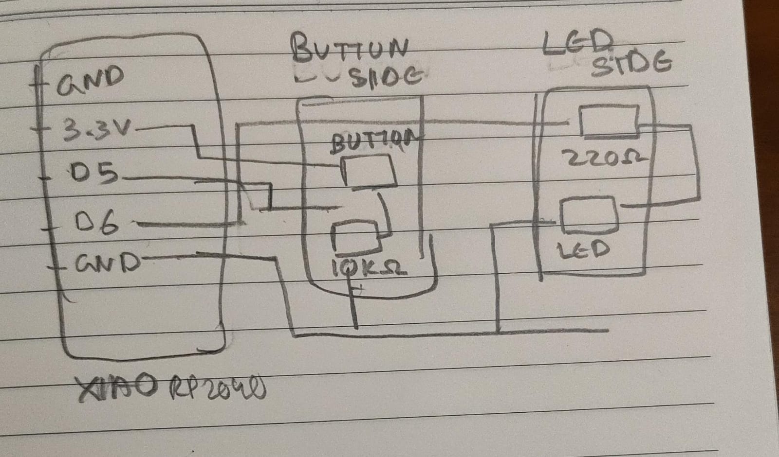
Following is the commented code for the program:
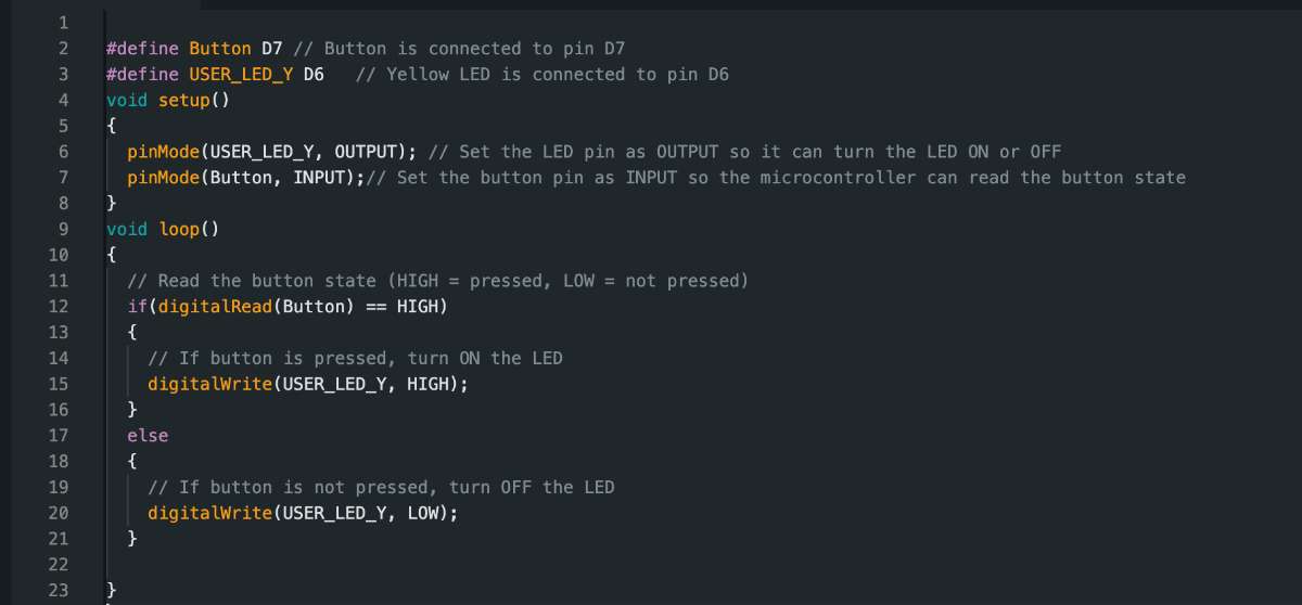
click here to copy code
XIAO RP2040is a tiny microcontroller board made by Seeed Studio, using the RP2040 chip (from Raspberry Pi).It features a dual-core ARM Cortex-M0+ processor running up to 133 MHz, 2 MB of flash memory, and 264 KB of SRAM. The board includes 11 GPIO pins that support digital input/output, analog input (ADC), PWM, I2C, SPI, and UART communication.
The board provides 11 GPIO pins that support multiple communication and control interfaces, including:
Digital input and output
Analog input (ADC)
PWM (Pulse Width Modulation)
I2C communication
SPI communication
UART communication
The board uses a USB-C connector for programming and power supply. Due to its compact size and versatile features, it is well suited for embedded systems, Internet of Things (IoT) devices, robotics applications, and wearable electronics. The XIAO RP2040 can be programmed using Arduino, MicroPython, CircuitPython, or C/C++.
The RP2040 microcontroller is designed by Raspberry Pi and is used in many development boards including the XIAO RP2040.Key Specifications
Dual-core ARM Cortex-M0+ processor
Clock speed up to 133 MHz
264 KB SRAM
No internal flash (uses external memory)
USB 1.1 support
Programmable I/O (PIO)
Pinout:
(img-Raspberry Pi RP2040 Datasheet)
Hardware Overview
(Image Source)
XIAO ESP32-C6
ESP32-C6 is a low-power microcontroller developed by Espressif that includes built-in Wi-Fi and Bluetooth connectivity. It uses a 32-bit RISC-V processor and is designed for wireless applications such as IoT devices, smart home systems, and robotics. The XIAO ESP32-C6 is a low-power microcontroller developed by Espressif that includes built-in Wi-Fi and Bluetooth connectivity. It uses a 32-bit RISC-V processor and is specifically designed for wireless applications.
This microcontroller is suitable for applications such as:
IoT systems
Smart home devices
Robotics
The ESP32-C6 can connect directly to the internet and control external components such as sensors, motors, and LEDs. It can also communicate with web servers and cloud platforms without requiring a wired connection. It supports GPIO, ADC, PWM, SPI, I2C, UART, and USB interfaces, making it ideal for fully wireless embedded systems like a desktop companion robot.
XIAO ESP32C6 Pin List
The Arduino IDE is used to write, compile, and upload programs to microcontrollers. To learn about the arduino basic function, check out this Website.
Installing ARDUINO IDE
Go to - Arduino
to install and follow the given steps:
Downloaded and installed the Arduino IDE from the official Arduino website.
Installing XIAO RP2040 Support in Arduino
By default, Arduino does not support the XIAO RP2040 board. To program the XIAO RP2040, you need to install the board support package in Arduino.Steps to Install XIAO RP2040 Board Support:
Open ArduinoIDE
Go to File → Preferences (Arduino → Settings on Mac)
In the "Additional Boards Manager URLs" field, add:https://github.com/earlephilhower/arduino-pico/releases/download/global/package_rp2040_index.json
Click OK
Go to Boards Manager (Tools → Board → Boards Manager)
Search for "Raspberry Pi Pico"
Install the "Raspberry Pi Pico/RP2040" board package
Follow the same format to install the XIAO ESP32C6 board support package, only difference is add the following to the board manager:
https://raw.githubusercontent.com/espressif/arduino-esp32/gh-pages/package_esp32_index.json
Go to "select board" panel on top of the page
select the board of your choice
After completing these steps, the Arduino IDE was ready for programming.
I have listed some definitions for some terms used in programming:
Function: A block of code that performs a specific task and reused at different parts of the code, eg: sleep in Micropython
Class: A 'blueprint' for creating objects, eg: Pin in Micropython
Object: A specific implementation of the class, with variables containing data specific to that object
Module: A file containing multiple Python functions, classes, and variables. eg: machine
Loop: A loop is used to repeatedly execute a block of code until a specified condition is met.
Example:
while True: in Python
void loop() in Arduino
If no condition is specified, the loop runs indefinitely (infinite loop).
Breadboard Components Introduction
A breadboard is a fundamental tool for prototyping electronic circuits. It allows you to build circuits without soldering, making it ideal for testing and experimentation.
Breadboard Components:
Breadboard: A plastic board with holes connected by metal strips on the inside, allowing components to be inserted and connected.
LEDs (Light Emitting Diodes): Semiconductor devices that emit light when current flows through them. They have a positive (long leg - anode) and negative (short leg - cathode) side.
Resistors: Components that limit current flow. For LEDs, a current-limiting resistor (typically 220Ω or 330Ω) is used to prevent damage.
Jumper Wires: Wires with connectors on both ends used to connect components on the breadboard.
Push Button (Switch): A mechanical switch that opens or closes a circuit when pressed, commonly used for user input.
Power Supply: Usually connected to the breadboard's power rails (positive and ground/negative).
All three breadboard experiments in this documentation use these basic components in different configurations to control LEDs and other outputs.
Program 1: Controlling an external LED
Language: C/C++
Microcontroller: RP2040
Board: Rasberry Pi Pico
Environment: ARDUINO IDE
click here to copy code
#define creates a constant named USER_LED_G.
It assigns the value 16, which is the GPIO pin number where the LED is connected.
This makes the code easier to read and modify.
setup() runs only once when:
- The board is powered on, or
- The reset button is pressed.
pinMode() sets the pin mode.
OUTPUT → sets pin 16 as an output pin.
loop() runs continuously forever. This is where the main program runs repeatedly.
digitalWrite() sends voltage to the pin.
HIGH means ON (3.3V)
delay pauses the program.
1000 milliseconds = 1 second
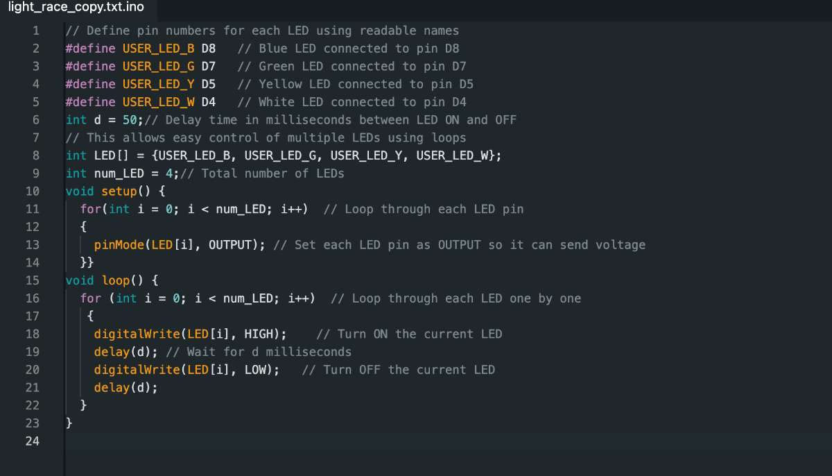
Program 2: Controlling multiple LEDs
Language: C/C++
Microcontroller: RP2040
Board: Rasberry Pi Pico
Environment: ARDUINO IDE
Following is the commented code for the program:
click here to copy code
Program 3: Controlling an LED using button
Language: C/C++
Microcontroller: RP2040
Board: Rasberry Pi Pico
Environment: ARDUINO IDE
Following is the commented code for the program:
click here to copy code
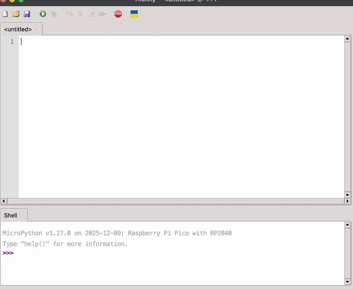
THONNY - Python IDE
Thonny is an integrated development environment (IDE) developed by the THONNY IDE team, tailored for beginners eager to learn Python programming(Thony uses micro Python). This free and open-source software provides a simplified solution to coding challenges, enabling users to focus on mastering the fundamentals of Python without unnecessary distractions. With its emphasis on ease of use, Thonny stands out as a key resource for novices entering the world of coding. This software is an ideal starting point for beginners or educators seeking a clear, visual, and accessible coding language.Installing THONNY
Clink on THONNY IDEto install THONNY and also to find information regarding the software.
It will take you to the following page:
Click on download, after downloading this is how the page looks like:
The following is the code(Micropython) run to blink various lights on the XIAO RP2040 board:
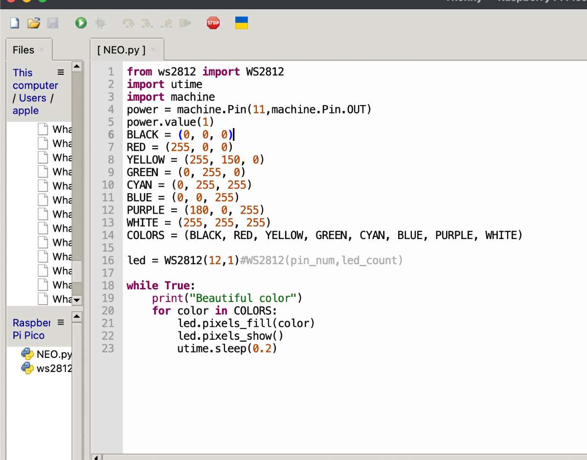
click here to copy code
Output:
The following are the main difference between both Enviorments:
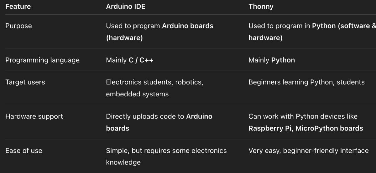
(prompt : Differentiate between ARDUINO IDE and THONNY IDE)