Individual Assignment
Moodboard:
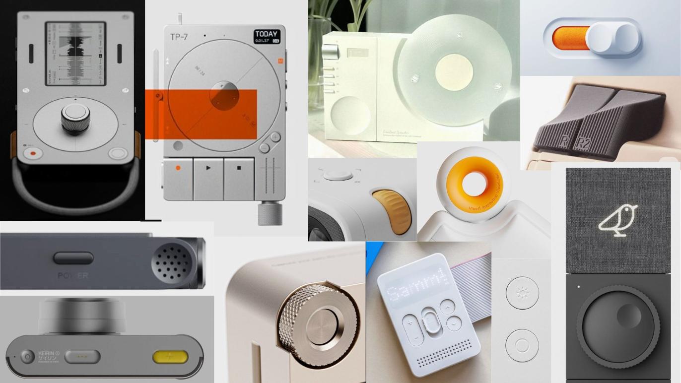 image credits: Pinterest
Sketches
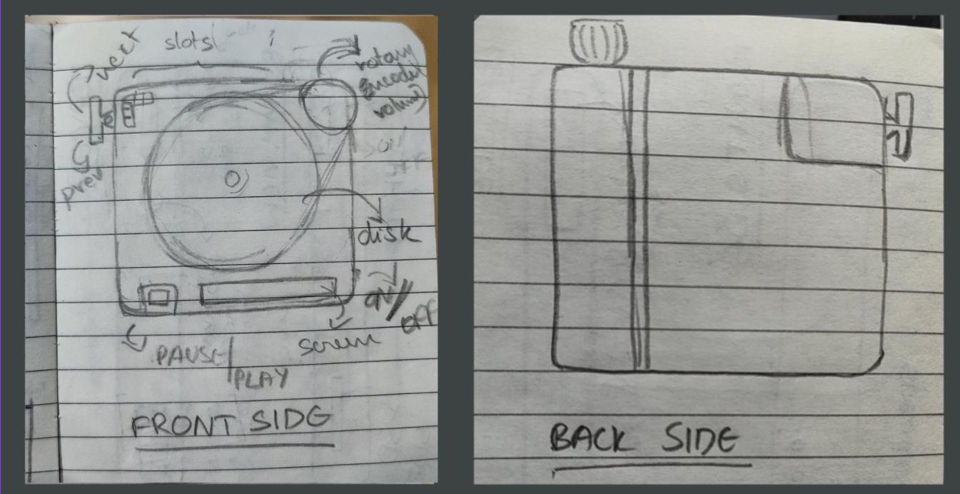
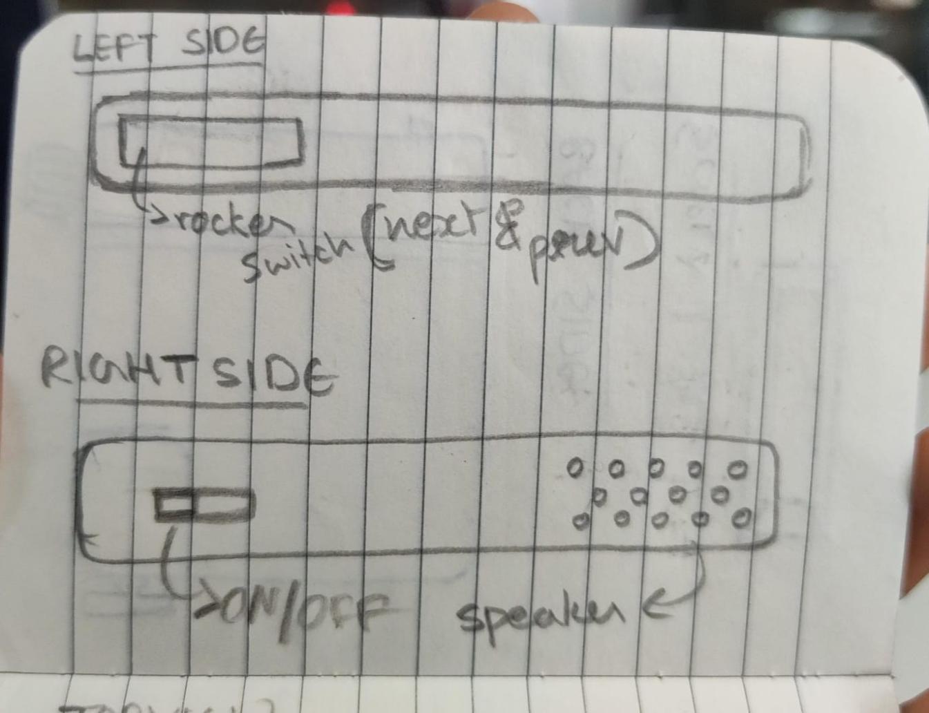
First i made sketches of the different iterations of my project: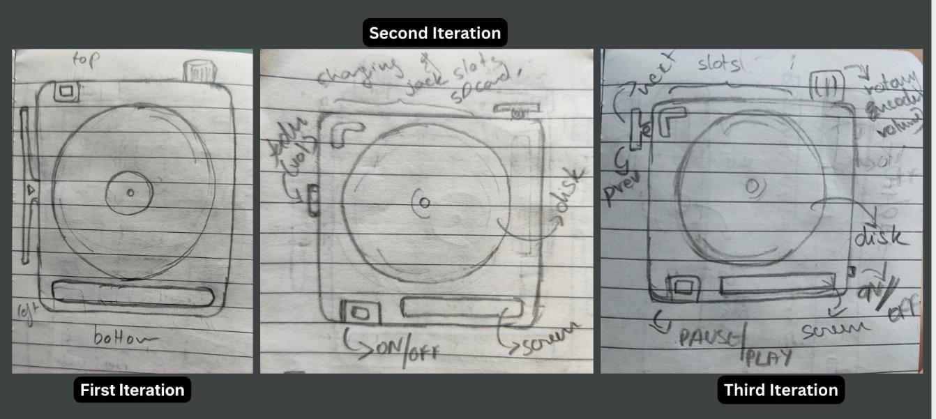
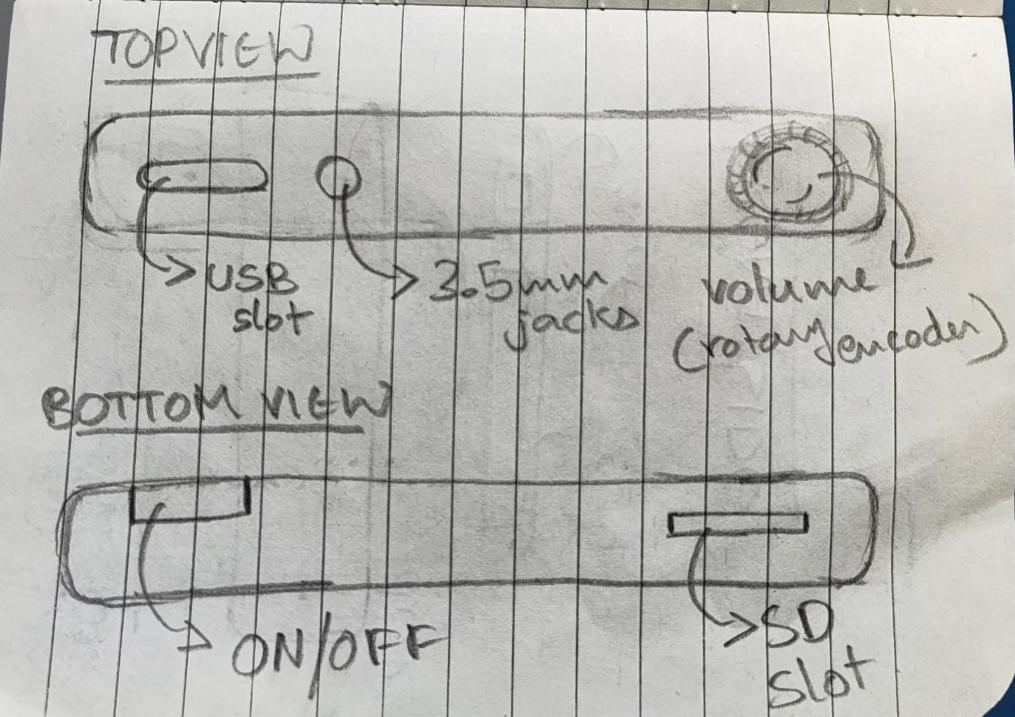
Exploded view
Exploded view of my product: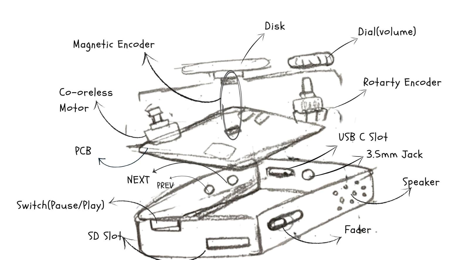
User Flow Diagram
We had to make a user flow to understand the product from a user's point of view and it also aids in improving the overall experience. I used draw.io to make the diagrams.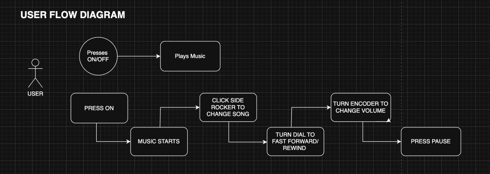
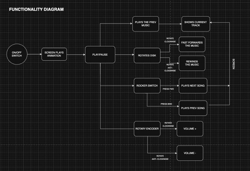
Functionality Diagram
This diagram maps out everything PixelJam can do, starting from the controls and ending at what shows up on the screen. It has an ON/OFF switch to power on the device, then the screen plays an animation, and then the device sits at Play/Pause, ready to use.
From there, each physical control branches off into its own action:
- The disk is the heart of it — rotating it clockwise fast forwards the music, and rotating it anti-clockwise rewinds it. There are also controls to play the previous track.
- The rocker switch handles track changes — pressing it forward plays the next song, and pressing it backward plays the previous song.
- The rotary encoder controls volume — turning it clockwise raises the volume, and anti clockwise lowers it.
On the far right, almost every action feeds back to the screen, which shows the current track and the seek position, so the user always gets visual feedback for what they just did. The point of this diagram is to show how each input maps to a specific output before any of it was built.
 Block diagram showing all subsystems
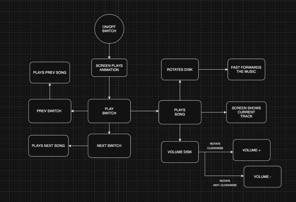
Bill of Materials:
| SL NO. | Item | Qty | Source | Price (₹) | Status |
|---|---|---|---|---|---|
| 1 | ESP32-S3 Sense | 1 | Fablab Inventory | 1427.00 | |
| 2 | Speaker | 1 | Amazon | 131.00 | |
| 3 | Coreless Motor | 1 | Electronic Spices | 39.00 | |
| 4 | 0.91 inch OLED Display Module | 1 | Fablab Inventory | 138.00 | |
| 5 | Magnetic Encoder | 1 | Fablab Inventory | 175.00 | |
| 6 | Battery Charging Module Type C | 1 | Fablab Inventory | 15.00 | |
| 7 | 3.7V 2500mAh LiPo Rechargeable Battery | 1 | Hubtronics | 359.00 | |
| 8 | Tactile Switch | 1 | Fablab Inventory | 1.31 | |
| 10 | Slide Switch | 1 | Fablab Inventory | 13.00 | |
| 11 | Rotary Encoder | 1 | Fablab Inventory | 39.00 | |
| 12 | Micro SD Card Socket | 1 | Fablab Inventory | 13.00 | |
| TOTAL | 2350.31 | ||||
Schedule:
| Task Title | Start Date | Wildcard Week | Applications & Implications, Project Development | Invention, Intellectual Property & Income | Presentation Week | |||||||||||||||||||
|---|---|---|---|---|---|---|---|---|---|---|---|---|---|---|---|---|---|---|---|---|---|---|---|---|
| — | — | 16 | 17 | 18 | 19 | 20 | 21 | 22 | 23 | 24 | 25 | 26 | 27 | 28 | 29 | 30 | 31 | 1 | 2 | 3 | 4 | 5 | 6 | 7 |
| Schematic Design | 19/5/26 | |||||||||||||||||||||||
| PCB Design & Soldering | 19/5/26 | |||||||||||||||||||||||
| Electronic Testing | 20/5/27 | |||||||||||||||||||||||
| Electronic Integration | 21/5/26 | |||||||||||||||||||||||
| Firmware (Core) | 23/5/26 | |||||||||||||||||||||||
| Documenting Wildcard Week | 17/5/26 | |||||||||||||||||||||||
| Documenting Application | 24/5/26 | |||||||||||||||||||||||
| UI Development | 1/6/26 | |||||||||||||||||||||||
| Designing Mechanism | 16/5/26 | |||||||||||||||||||||||
| Testing of Mechanisms | 16/5/27 | |||||||||||||||||||||||
| Documenting Invention | 31/5/27 | |||||||||||||||||||||||
| Enclosure Design | 25/5/26 | |||||||||||||||||||||||
| Integration | 28/5/26 | |||||||||||||||||||||||
| Documentation & Final Prep | 2/6/26 | |||||||||||||||||||||||
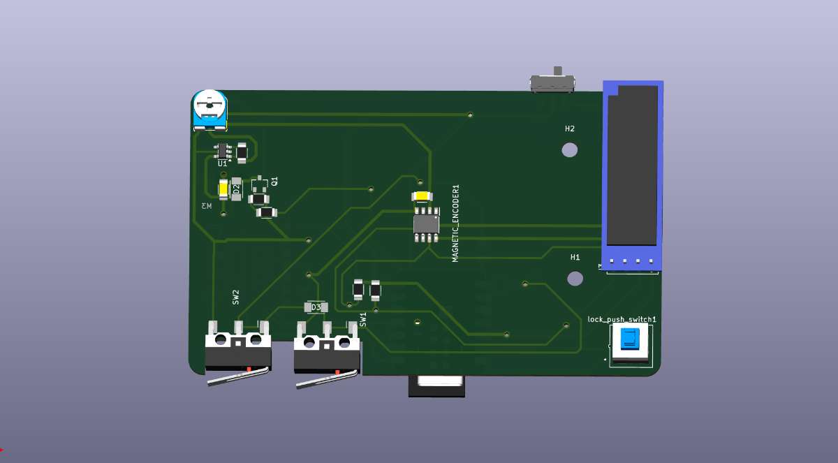
Wiring and electronics
I had designed my PCB to fit in maximum components to minimize the wiring and to make it as compact as possible.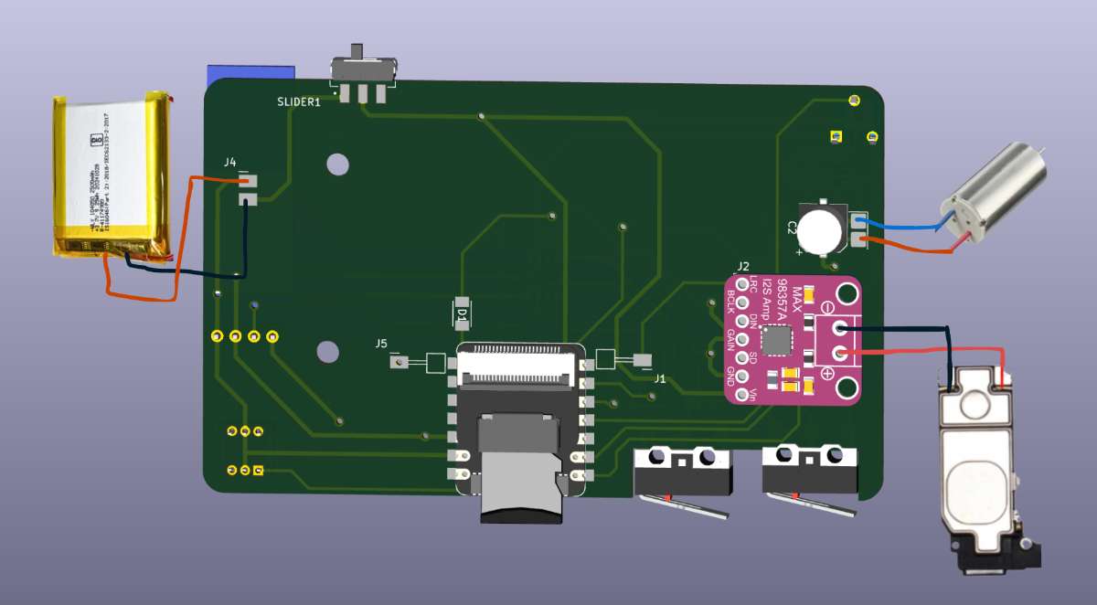 Here, the battery i am using is 3.7v 2500mAh LiPo Rechargeable Battery.
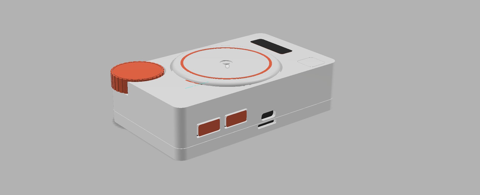
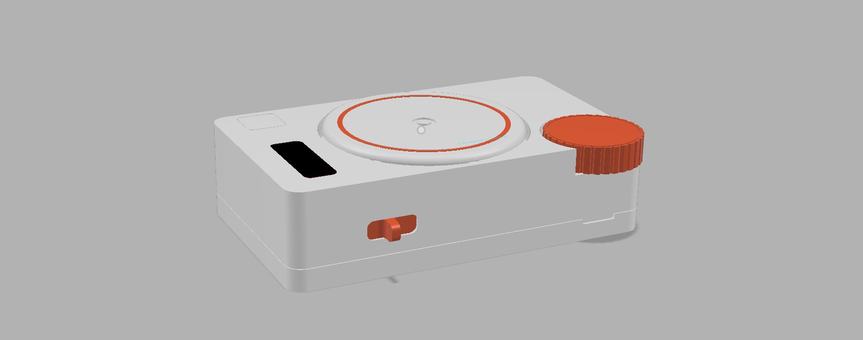
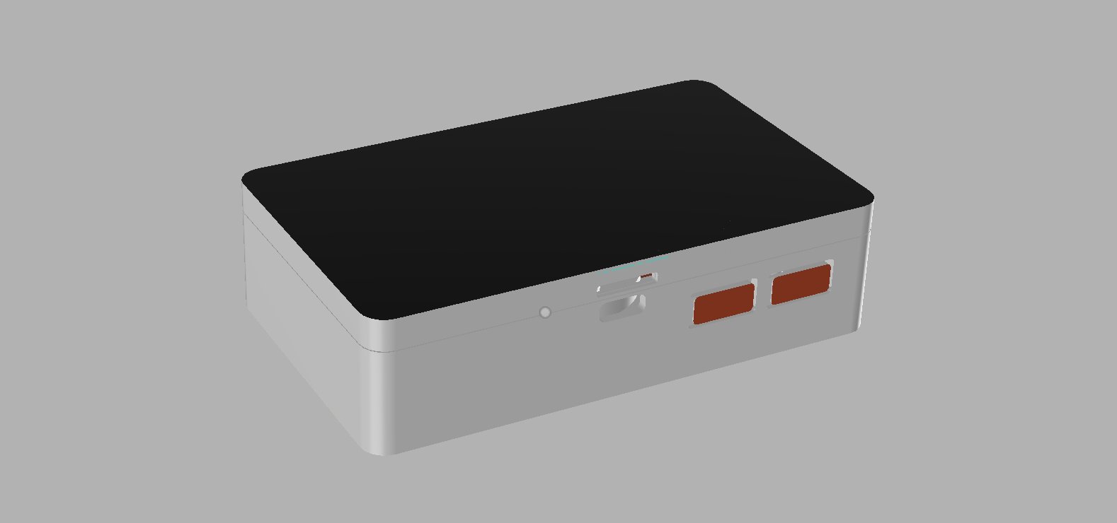
Rendered Images
Following are the Rendered images of my product made in Fusion 360 shown from different angles and perspectives :
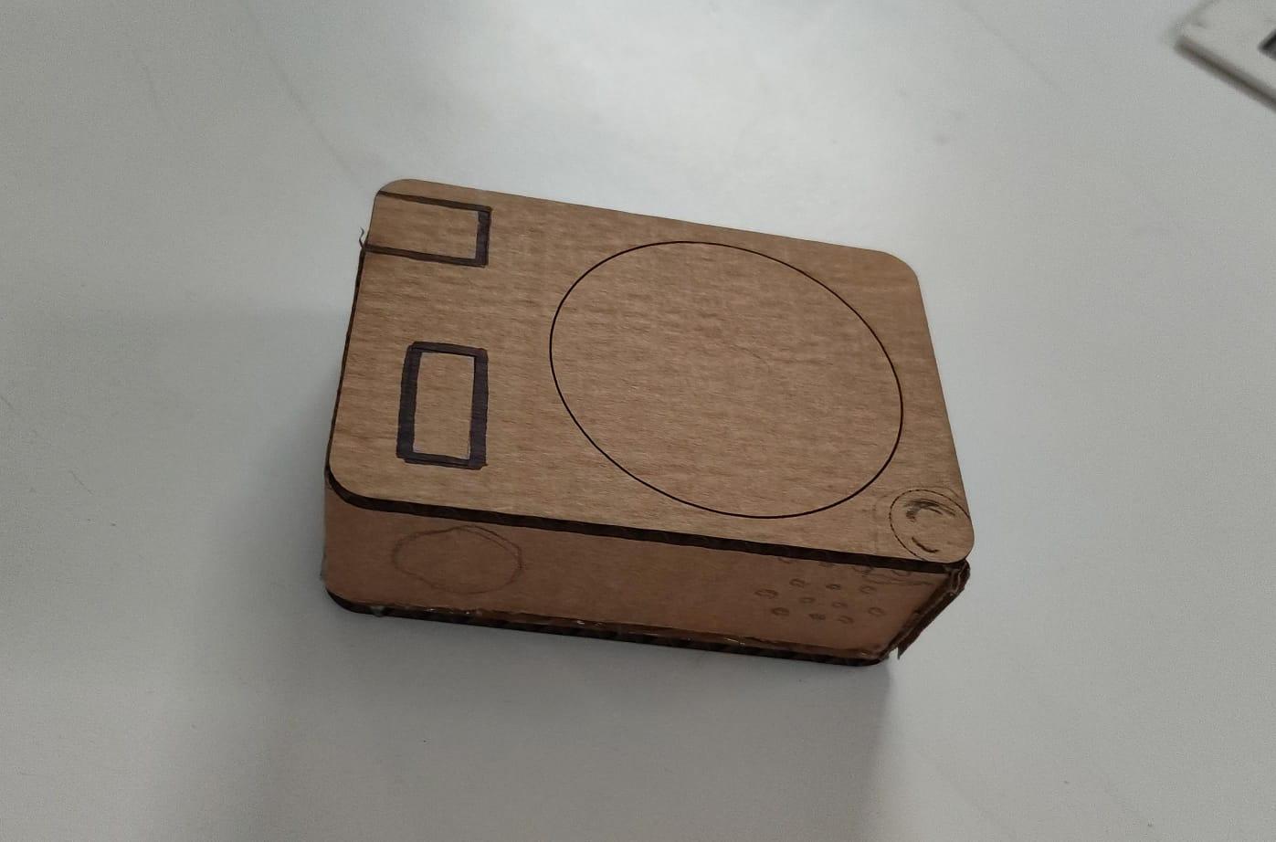
 I made the prototype by laser cutting the cardboard :
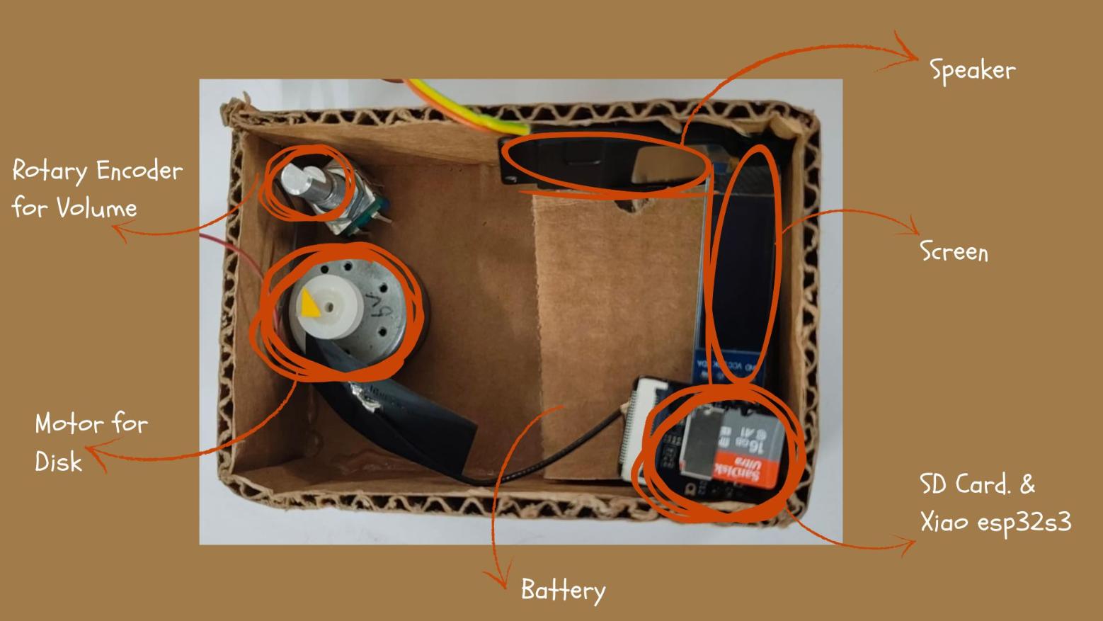
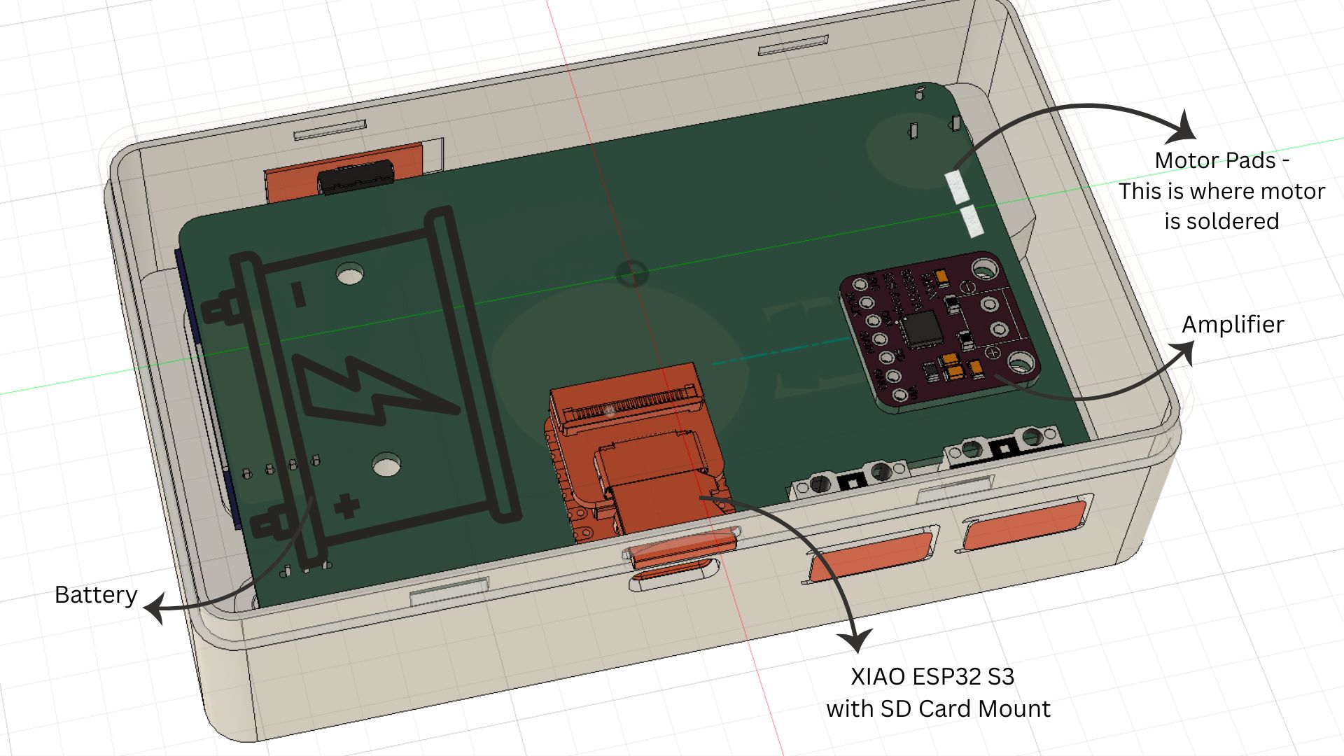
 The following image shows how the inner components will be arranged :
Disk Mechanism
This week i also figured out how i want my rotating disk mechanism to function, as my instructor, Saheen's suggestion i tried to make the disk mechanism using magnets: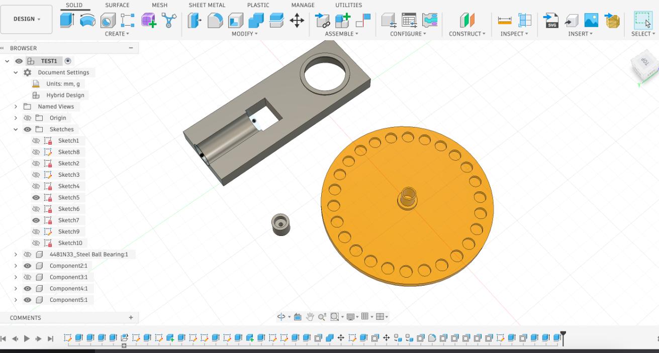
Took me a few tries to get the magnets size right:
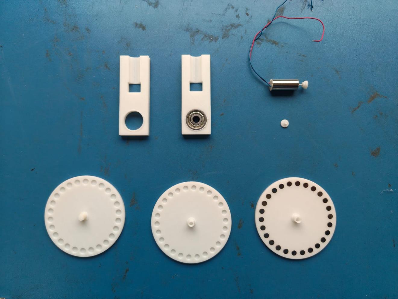 The following image elaborates on my First attempt at the mechanism:
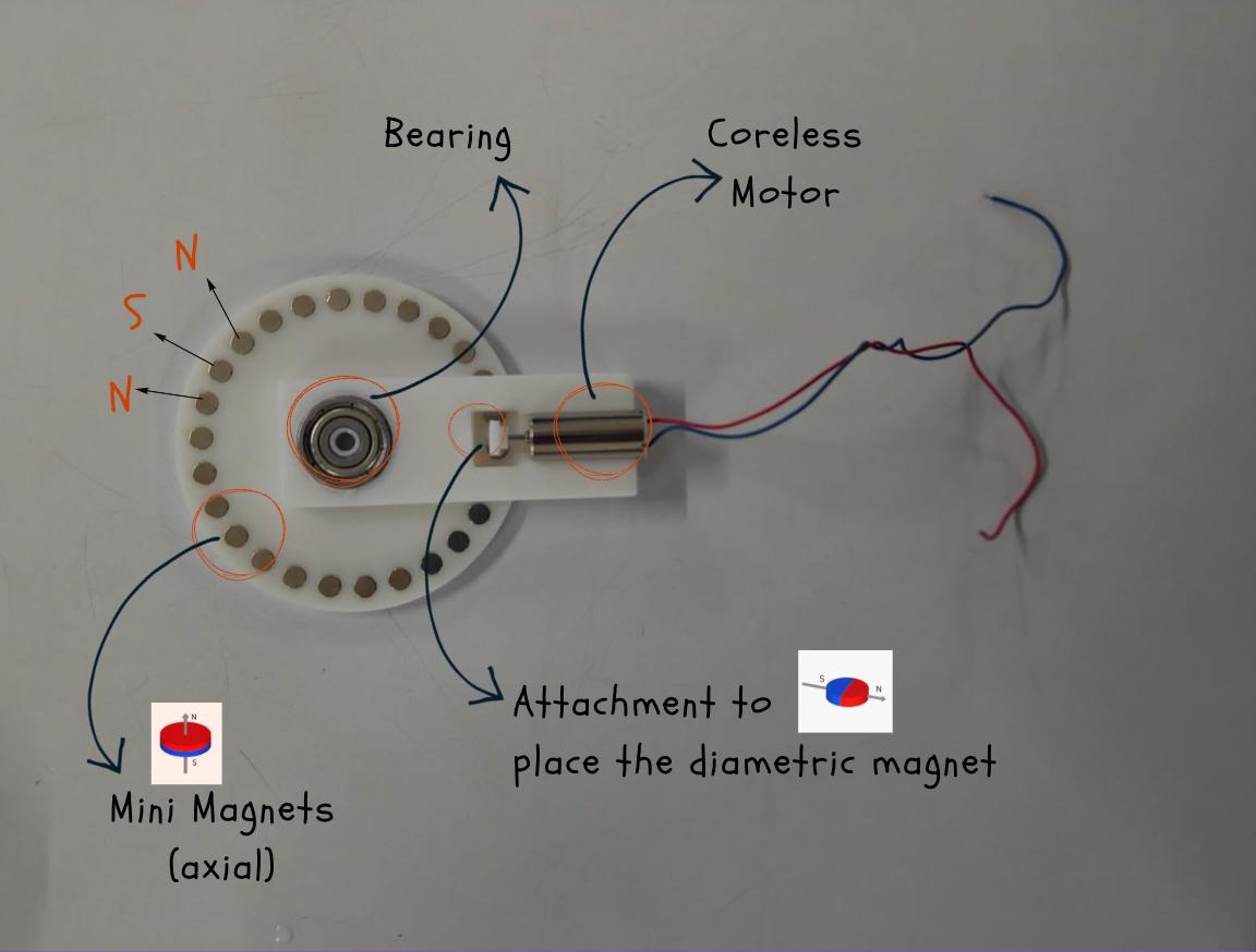 Now we found out that the dia magnet holder of the motor did not work, so we decided to switch it with another holder with axial magnets.
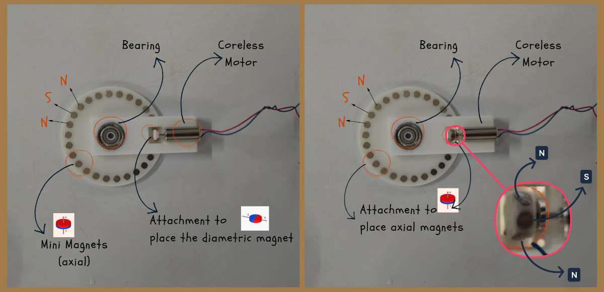 This worked perfectly:
Final Electronics integration inside the enclosure
This is how the final integration turned out. You can see that the disk mechanism has changed from magnets to a gear because while programming the device i realized that the motor was not able to rotate slow enough to allow the magnetic force to rotate the disk even when i added a capacitor to slow down the PWM. So i had to change the design of the mechanism with the help of Jogin, my instructor, last minute to a gear mechanism which would allow the motor to rotate the disk at a slower speed and with more torque.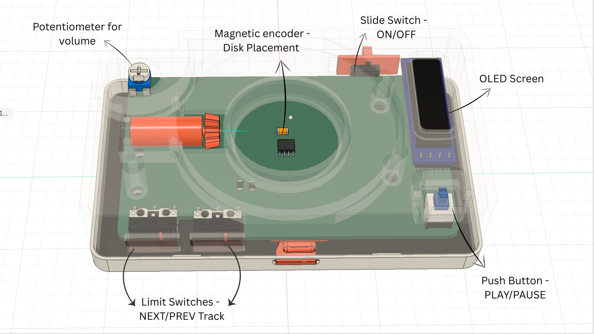
Final Files
Download Diagrams
Case Design Fusion360 file for Magnetic disk mechanism