Week 17 – Wildcard week
This week is about trying or deriving new computer-added process and exploring new machines.
The objective is to explore a new computer-added process with the new machine that is not covered in the previous weeks and make something with that process or machine. I decided to use embroidery machine to design and produce embroidery on a cotton cloth that I can use in my final project.
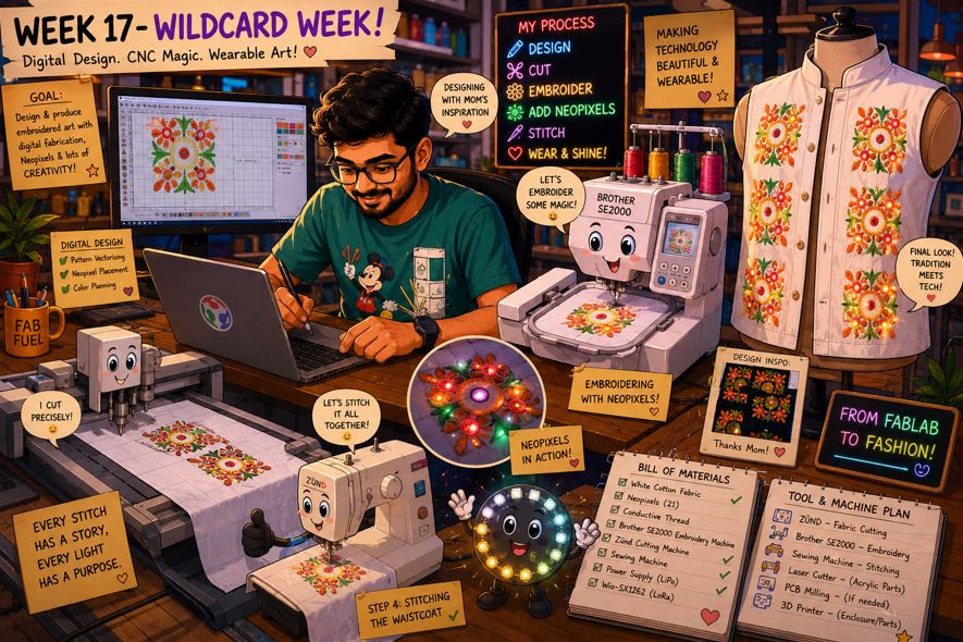
AI prompt ChatGPT: "Hey, I am in my week 17 Wildcard week, this week is about design and produce something with a digital process (incorporating computer-aided design and manufacturing) - I have decided to use Embroidery Machine - Brother se2000, first design a 2D embroidery design and then use machine to CNC Embroidery on a Cotton fabric and use it for the male waistcoat of my final project. in the embroidery I will stitch Neopixels. The Embroidery that I designed is from my Mom's embroidery reference. Can you please give me a animated fun image of me doing week 17 of my fab academy? "
Assignment Overview
- Design and produce something with a digital process (incorporating computer-aided design and manufacturing) not covered in another assignment, documenting the requirements that your assignment meets, and including everything necessary to reproduce it.
| Day | Activity | Status |
|---|---|---|
| Thursday | Class - Wildcard week possible options to explore | Completed |
| Introduction to Embroidery Machine Brother SE2000 🛠 adn Documentation | Completed | |
| Friday | 2D Embroidery Design 📐 | Completed |
| Saturday | Final Project - Updated the Schedule 📝 | Completed |
| Design, Produced and Tested "Embroidery Pixel" 🛠 | Completed | |
| Sunday | Documentation 📝 | Completed |
| Embroidery Material / Cloth from Local Shops | Completed | |
| Monday | Fabric Cutting on the ZUND machine 🛠 | Completed |
| Embroidery work using Brother se2000 🛠 | Completed | |
| Tuesday | Regional Review 👨🏫💬 | Completed |
| Embroidery work using Brother se2000 🛠 | Completed | |
| Wednesday | Stitching using Brother se2000 🛠 | Completed |
| Documentation 📝 | Completed |
Machine Embroidery
As the Embroidery work is involved in my final project, I chose to explore the digital embroidery process for my this weeks assignment.
Workflow : Hand Sketching (PNG) --> Fusion (DXF) --> 2D Design (SVG) --> Inkscape --> INK/Stitch (PES) --> BROTHER SE2000
BROTHER SE2000
Our Lab has Brother SE2000 Embroidery and Stitching Machine.
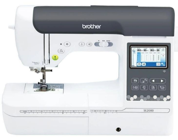
Below are some key details about the BROTHER SE2000 Machine:
| Specification | Details |
|---|---|
| Embroidery Area | Maximum embroidery area of 5" × 7" (18 × 13 cm). |
| Embroidery Speed | Up to 650 stitches per minute for embroidery and 850 stitches per minute for sewing. |
| Display | 3.7" LCD color touchscreen with on-screen editing features, including letter editing, zooming, resizing, rotating, repositioning, and combining embroidery designs. |
| Built-in Content | Includes 193 built-in embroidery designs and 13 built-in embroidery fonts. |
| File Transfer | Supports Wireless LAN (Wi-Fi), allowing embroidery files to be transferred directly from a PC using Design Database Transfer software without requiring a USB drive. |
Embroidery Design Workflow
| Step-by-step | Description |
|---|---|
| Create 2D Design | Prepare your embroidery artwork as an .SVG vector file using Inkscape or another vector graphics editor. |
| Verify Design Size | Check that the design fits within the embroidery hoop size (5" × 7") before exporting. Designs larger than the hoop area may be rejected or clipped by the machine. |
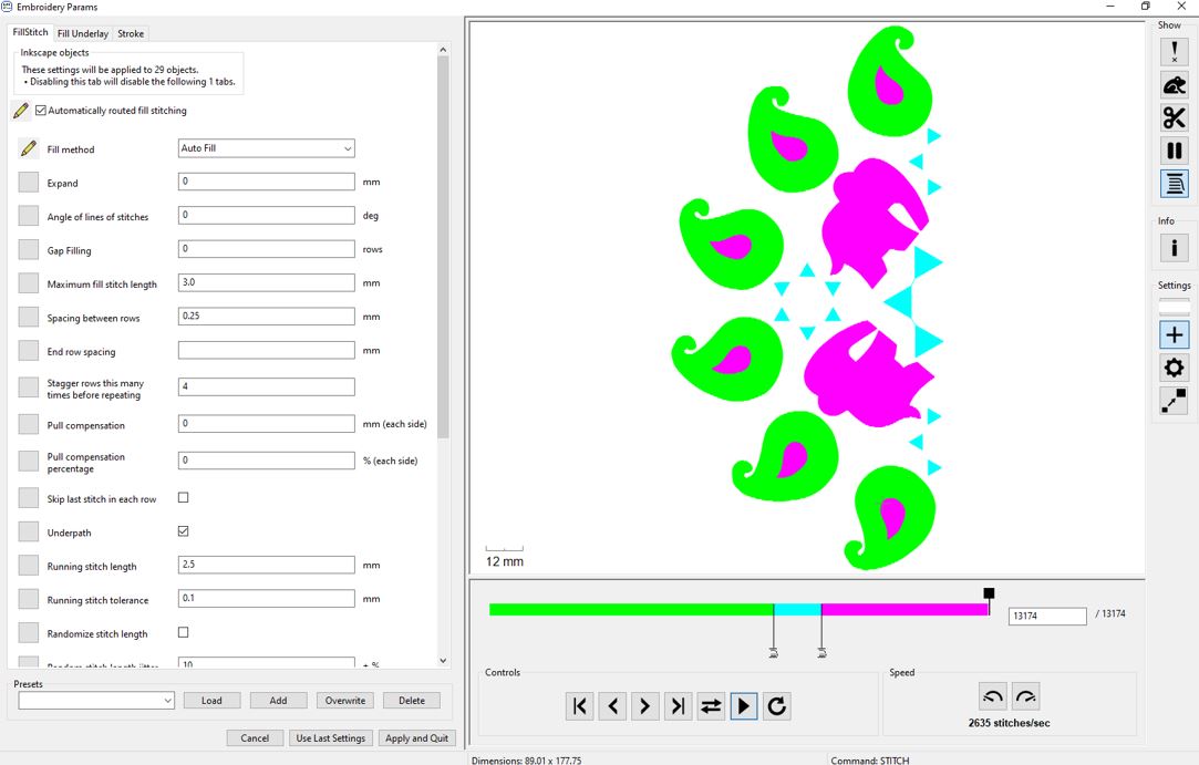
| Digitize the Design | Import the .SVG into embroidery digitizing software such as Brother PE-Design 11, Ink/Stitch, or Embird. I used Ink/Stitch. The software converts the vector artwork into stitch-by-stitch embroidery instructions. |
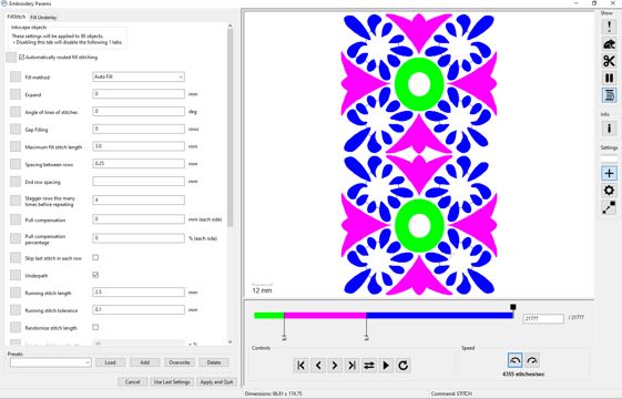
| Preview the Stitch Path | Use the Ink/Stitch Simulator (or equivalent preview tool) to verify the stitch sequence, or needle path errors before embroidery. |
| Export the Design | Export the final embroidery file in the .PES format, which is the native embroidery file format supported by the Brother SE2000. |
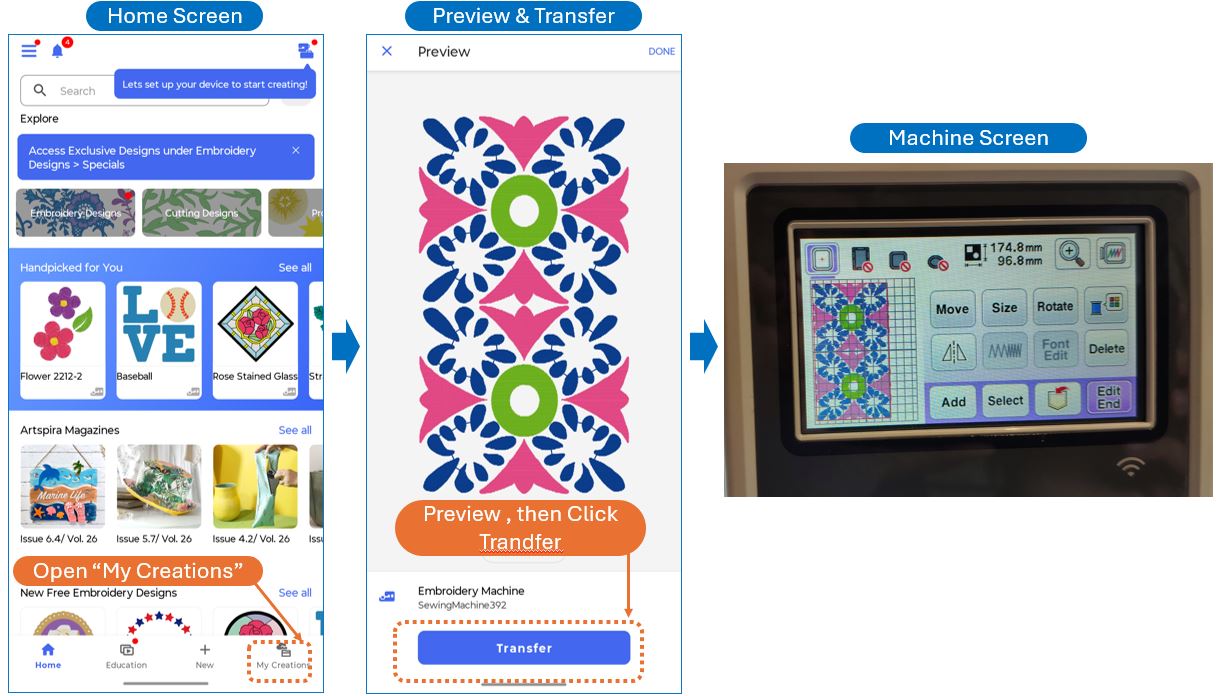
| Transfer to the Machine | Transfer the .PES file to the Brother Artspira mobile application. Ensure that both the mobile device and the embroidery machine are connected to the same Wi-Fi network before transferring the design wirelessly. |
Embroidery Design Rules
Before stitching a design on the final garment, it is important to follow a few basic embroidery design rules. These guidelines help improve stitch quality, reduce thread breaks, and prevent wasted fabric and materials.
| Rule | Recommendation | Why It Is Important |
|---|---|---|
| Test Stitch First | Always perform one test stitch on scrap fabric that matches the final garment material. | Embroidery quality, thread tension, and stitch density vary between fabrics such as cotton, satin, silk, and synthetic blends. |
| Stay Within the Hoop Area | Ensure the design fits within the 5" × 7" embroidery hoop before exporting. | Oversized designs may be rejected by the machine or stitched incorrectly. |
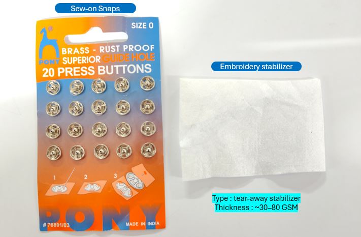
| Choose the Correct Stabilizer | Select an appropriate cut-away, tear-away, or wash-away stabilizer based on the fabric. | Proper stabilization improves stitch quality. |
| Avoid Excessive Stitch Density | Do not place too many stitches in a small area. | High stitch density increases thread breaks, needle heat, and fabric distortion. |
| Use Appropriate Stitch Types | Use Running Stitch for outlines, Satin Stitch for text and borders, and Fill Stitch for large areas. | Each stitch type is optimized for different embroidery features. |
| Check Simulation | Preview the embroidery sequence using the simulator before exporting. | Helps detect travel stitches, overlapping stitches, and stitching errors. |
| Use Quality Thread and Needle | Choose the correct embroidery needle and high-quality embroidery thread. | Reduces thread breaks and improves stitch consistency. |
Embroidery Material
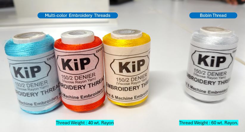
I purchased the material from a local shop name Tailor Smart, they have near to industry standard embroidery materials available for DIY embroidery community.
2D Sketching of Embroidery
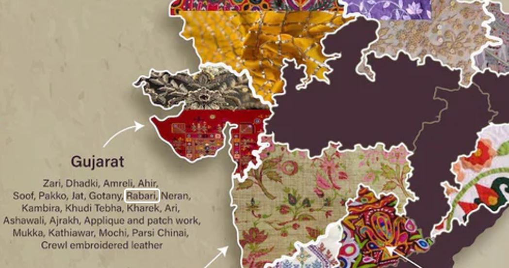
Different regions of India has different Embroidery Styles. I took reference of my mom's embroidery which is done with Rabari Style of Embroidery.
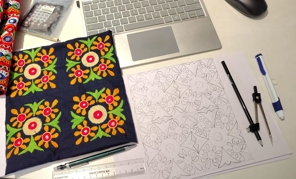
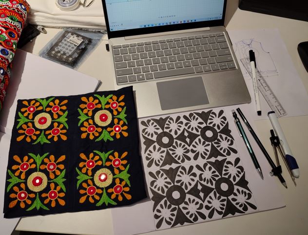
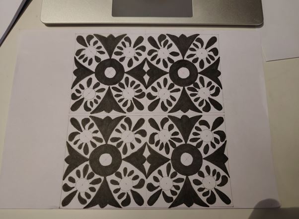
I decided to make two embroidery designs, for one I took reference from my mom's embroidery work. She made one piece of Kutchi embroidery style / Rabari embroidery style work.
Creating 2D Design Vector file (SVG)
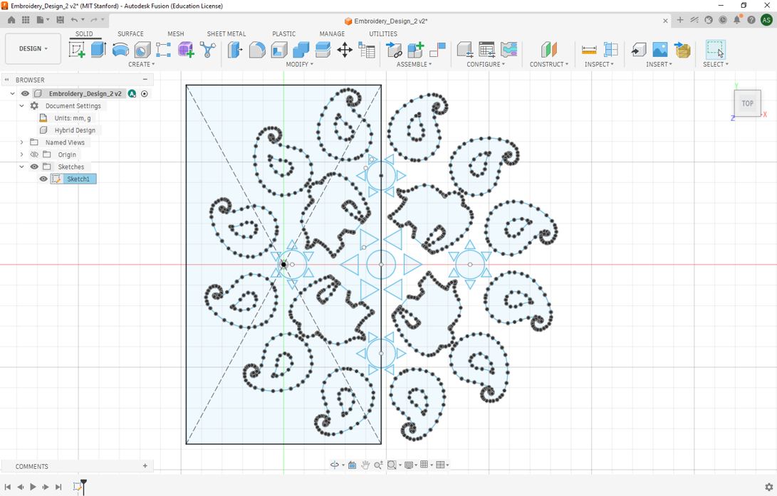
I used Fusion to generate SVG file. First I imported PNG file in to fusion then used Spline tool to drew outlines and finally used mirror tool to multiply the patent.
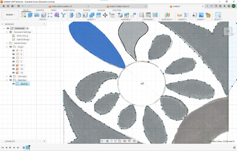
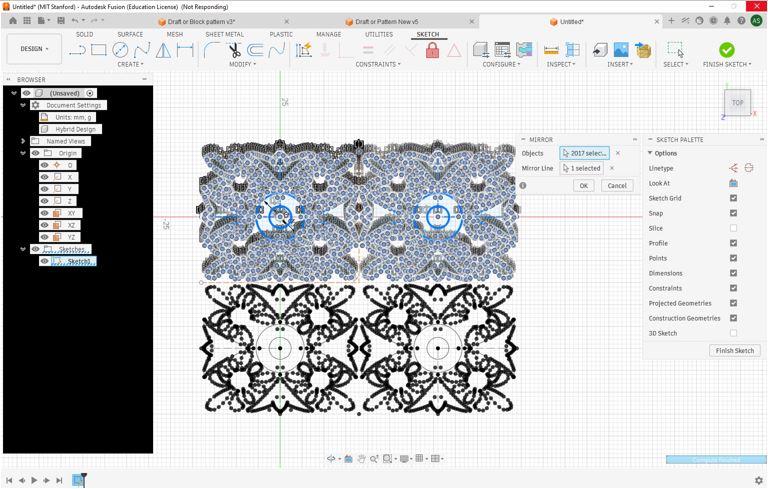
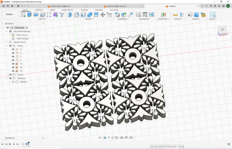
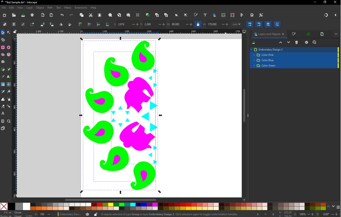
From above file I generated / exported a DXF file and used Concertio.co to convert DXF into SVG. You can download DXF file from here Embroidery_Fusion. Now opened the SVG file into Inkscape. I used Join Selected Nodes to join individual splines. First, Click Node Tool --> Select the two splines --> Select the joining nodes --> Join selected nodes. I need to do this only for splines that are touching the mirror lines.
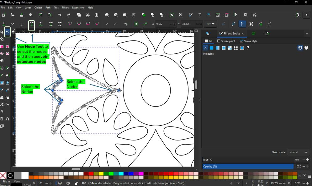
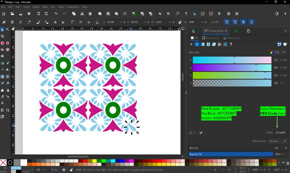
I filled the color using HEX Code values of different colors. Boolean Operation : Select inner circle --> Object --> Raise to top --> Select both circles --> Path --> Difference.
Ink/Stitch Simulator
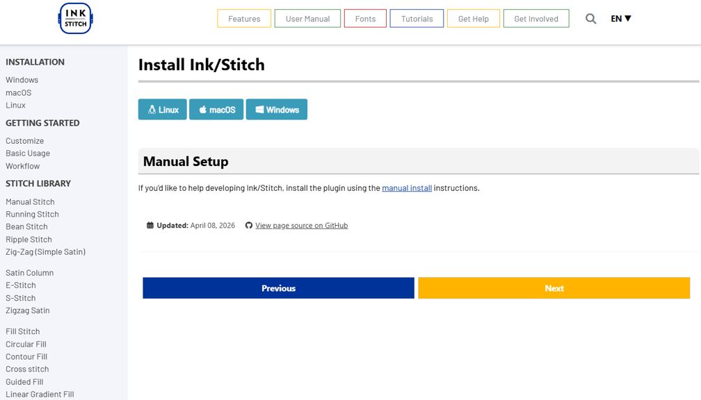
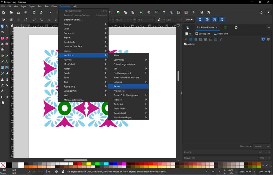
Download Ink/Stitch Extension for Inkscape. The Ink/Stitch automatically finds the Inkscape extension folder and installs itself.
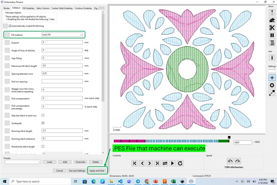
Transfer (.PES) file to the Machine
I download Brother Artspira Android App for WIFI transfer of .PES file to Embroidery Machine. First, I took the .PES file onto my mobile phone and then opened Artspira App and followed below steps.
Next is to Load the design and Verify with Trial Function : The Trial function allows you to verify that the embroidery design fits within the fabric and hoop before stitching begins. The machine traces the outer boundary of the design without sewing, helping prevent positioning errors and collisions.
- Load/select the embroidery design and position it on the LCD touchscreen.
- Press the Trial button on-screen icon (as shown in the below video).
- Observe the Boundary - The embroidery carriage will trace the four corners and edges of the design's bounding box without stitching.
- Verify Clearance - Ensure the entire design remains within the fabric area and does not collide with hardware.
- Finally, Begin Embroidery - Once the design position is confirmed, press Start to begin the embroidery process.
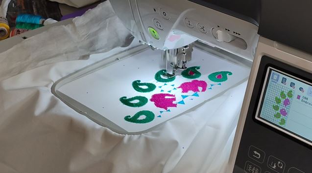
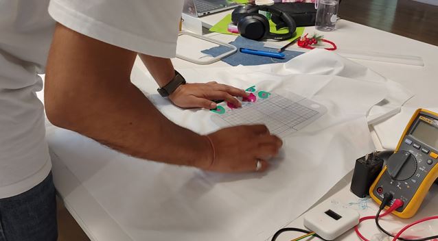
Using the Reference frame to continue the second patch of embroidery in continuation without miss-alignment.
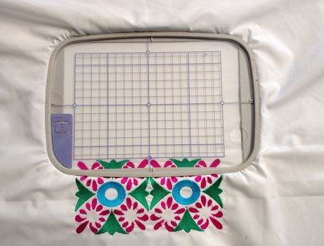
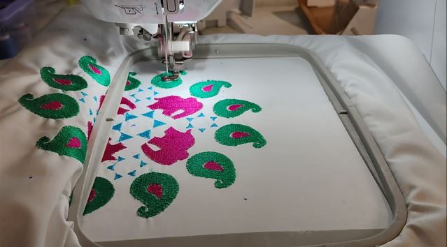
Continuation of Second half of the Embroidery.
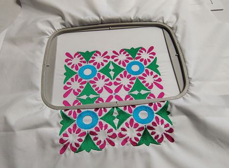
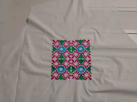
Another Design of Embroidary
I followed the same above explained steps and made the second Embroidery design as follow.
What Went Wrong
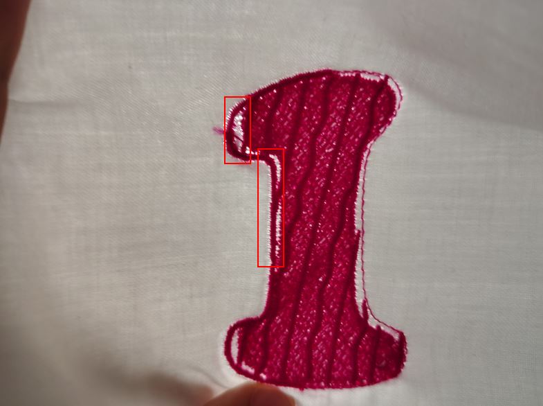
The first test run stretched the Fabric it turned created visible gao at the borders of the embroidery. This was even after using filling paper on the back of the fabric.
What I Learned
The fabric quality and density matters because the threads of embroidery borders and fill create compression, to withstand this we use lining paper and also the fabric has to have sufficient thickness and density.
Embroidery quality, thread tension, and stitch density vary between fabrics such as cotton, satin, silk, and synthetic blends.
I changed the fabric to a better quality.
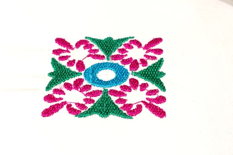
With this new thick cotton fabric, I again run a test embroidery to confirm the better embroidery result.
Garment Pattern cutting
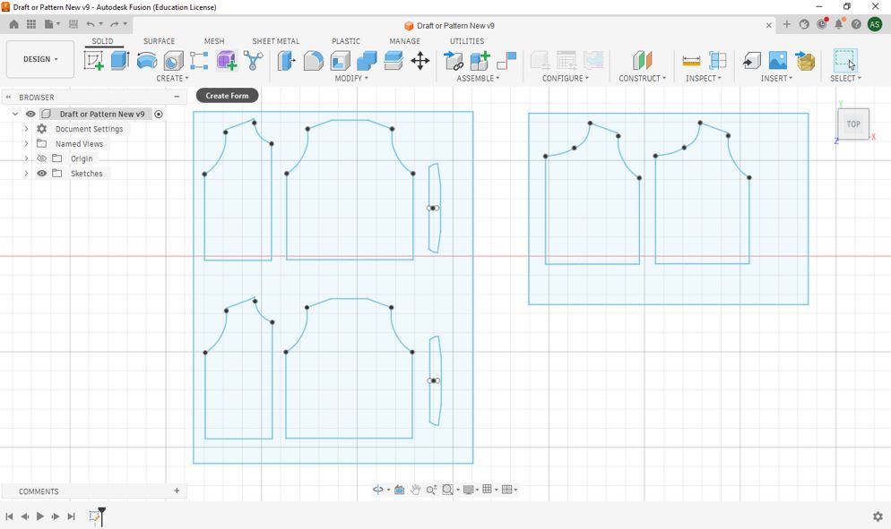
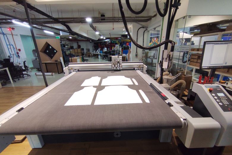
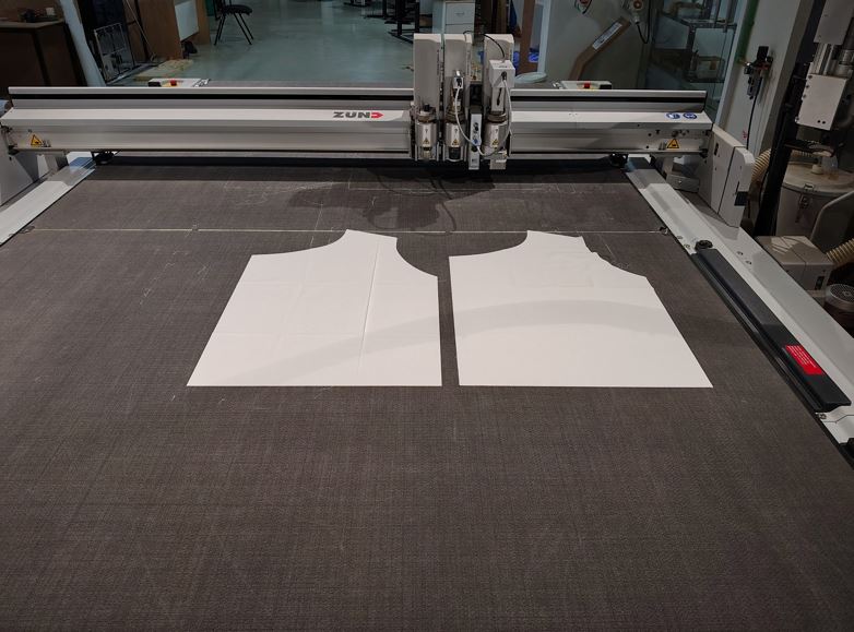
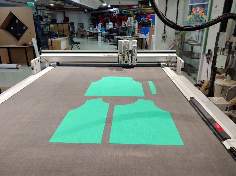
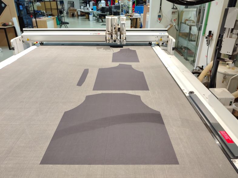
As I decided to make the waistcoat within the lab, first thing is to cut the patterns for my size using Zünd cutting machines and then do the embroidery work and Stitching using BROTHER SE2000.
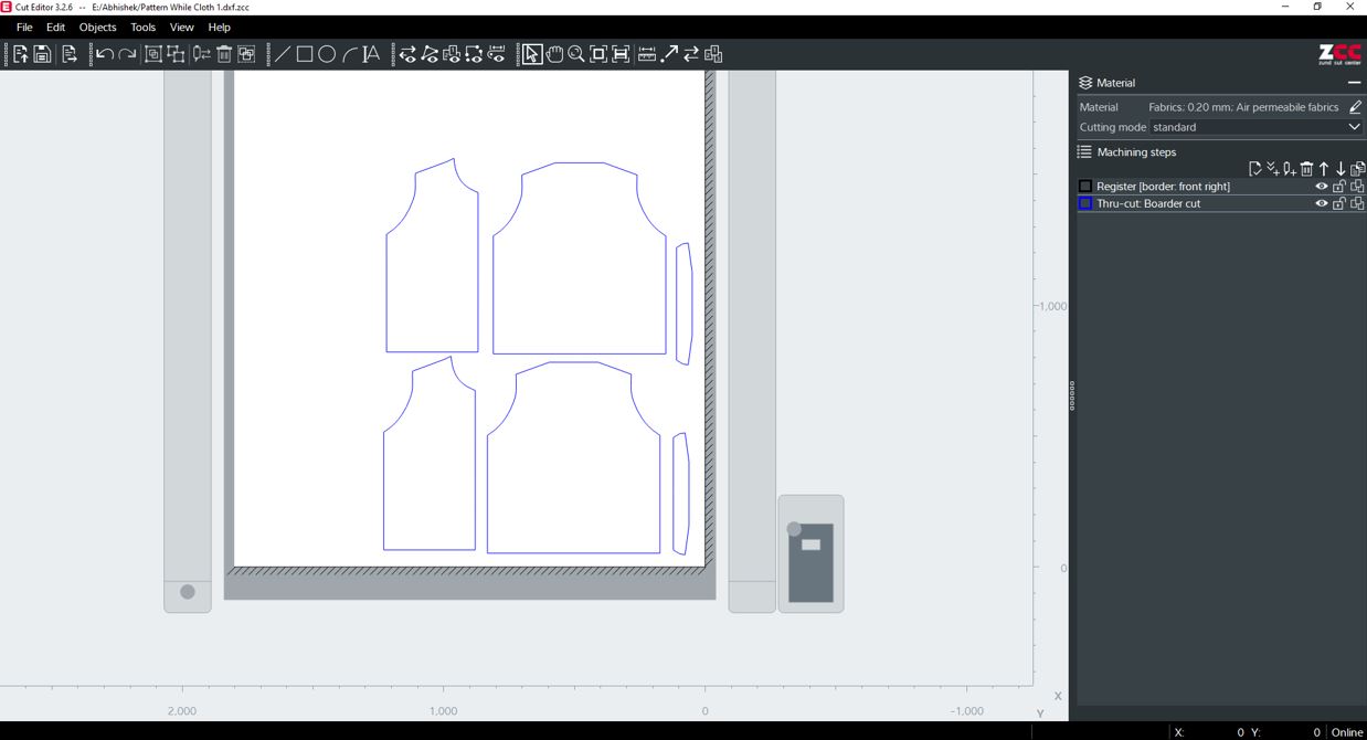
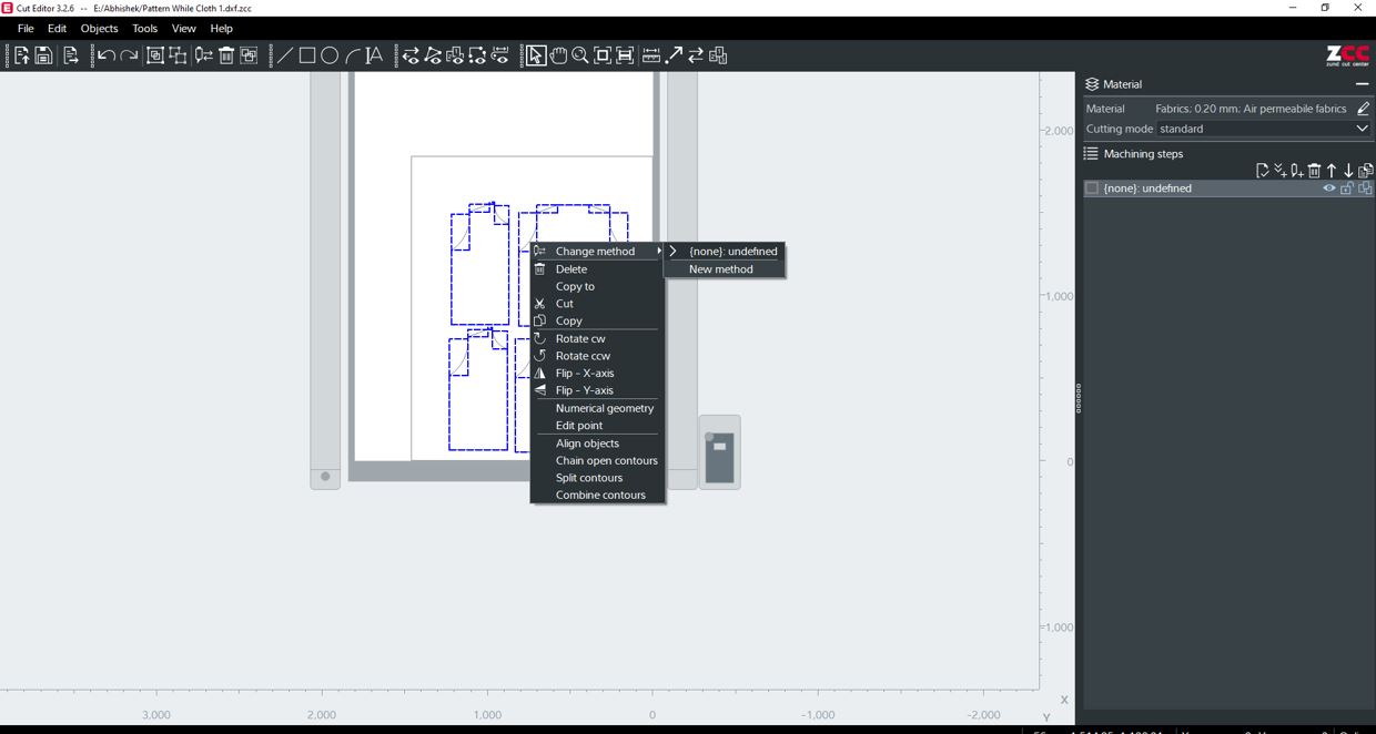
Digital Fabrication Process : 2D Garment Draft in Fusion (DXF) --> Cut Editor : CAM Files --> Cut Queue (Job Server) --> Cut Center (Job / CAM Executor) --> Zund Machine
2D Garment Draft
Cut Editor
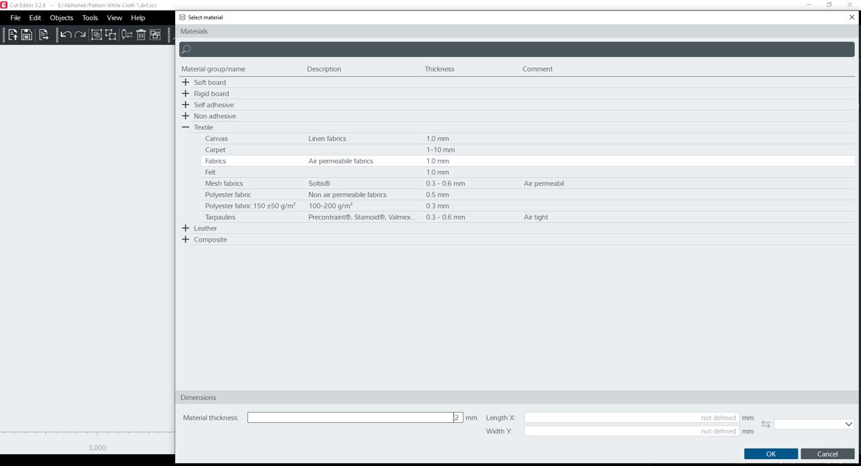
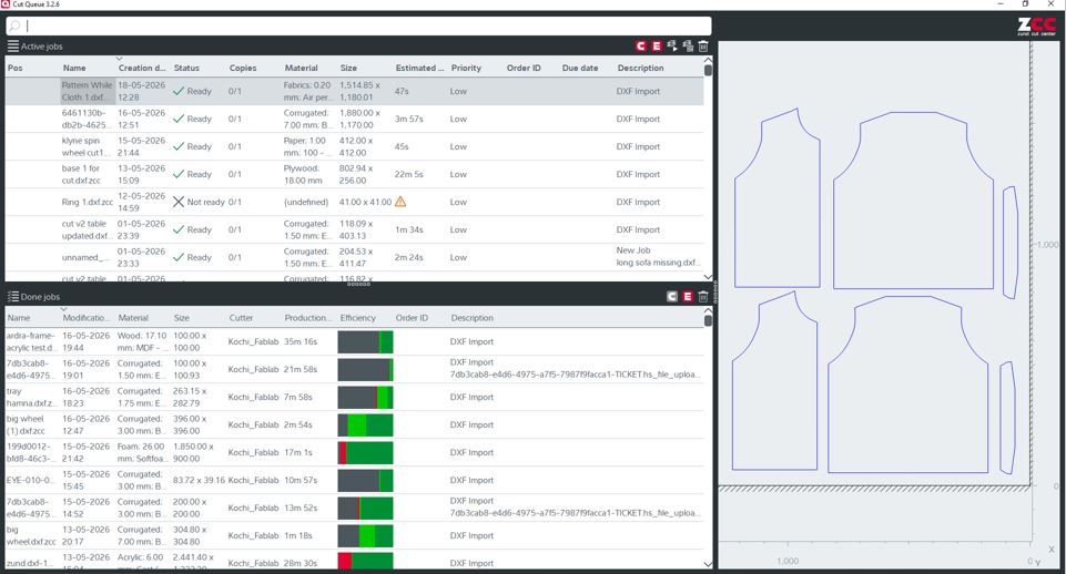
Cut Center
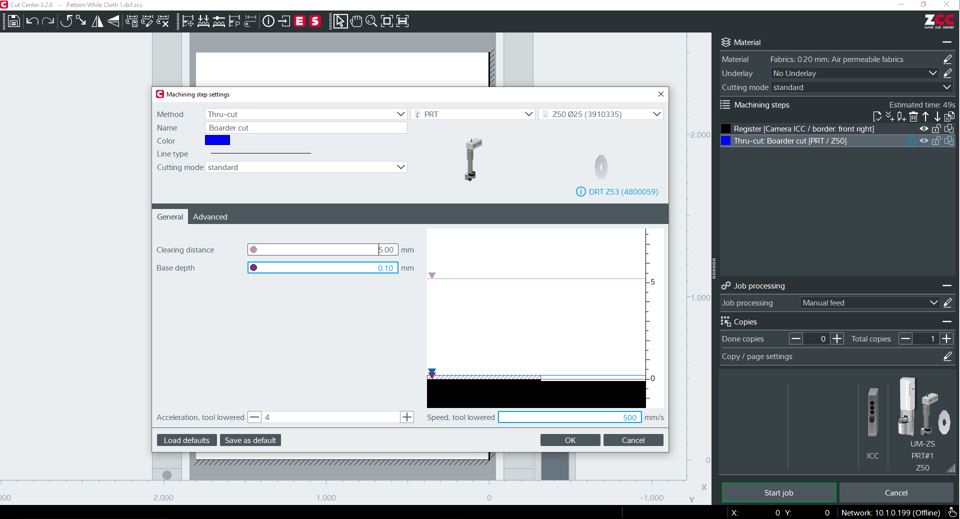
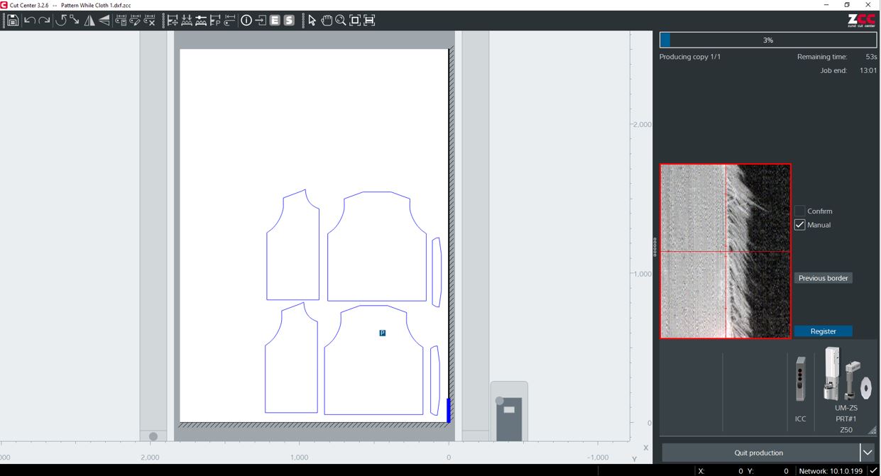
Zund Machine
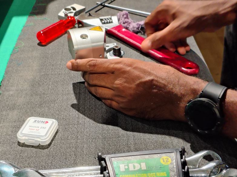
What Went Wrong
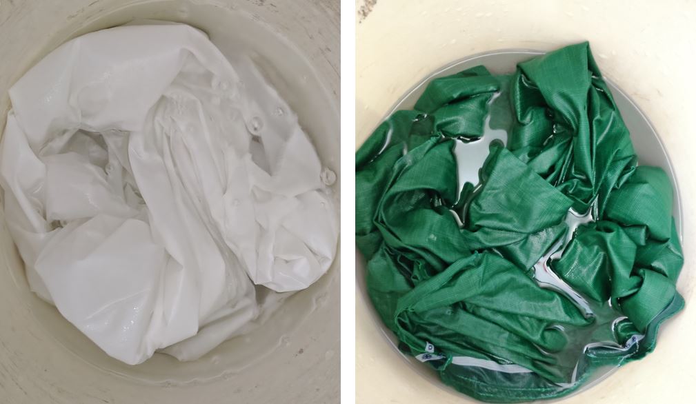
The Green Fabric encoded issue in cutting, we updated the cutting depth however still it was not able to cut the green cotton fabric, thus we checked the sharpness of rolling blade we found that it had lost its sharpness compared to new blade thus the end effector rolling blade need to be changed.
Embroidery Pixel Module
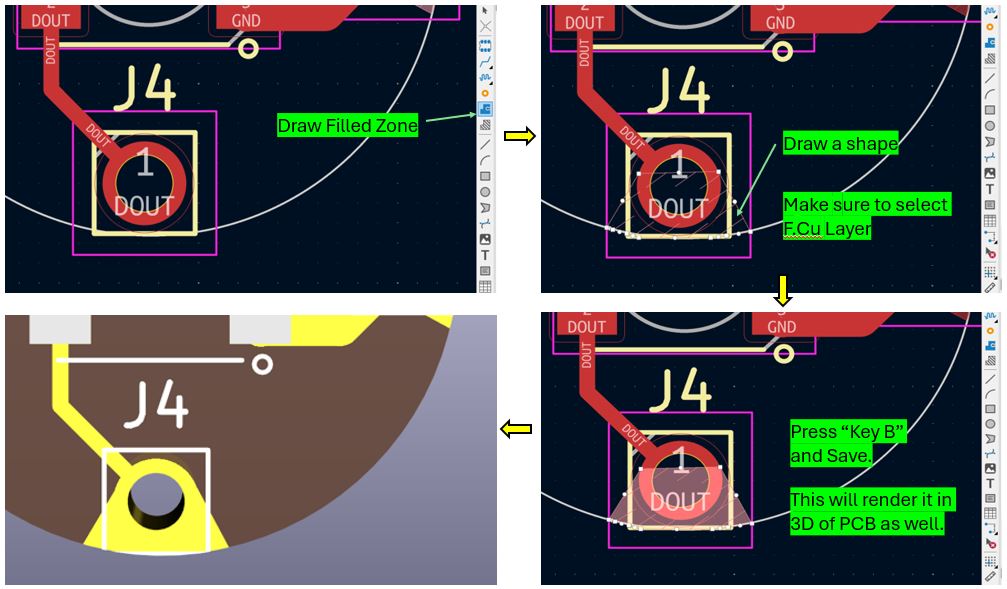
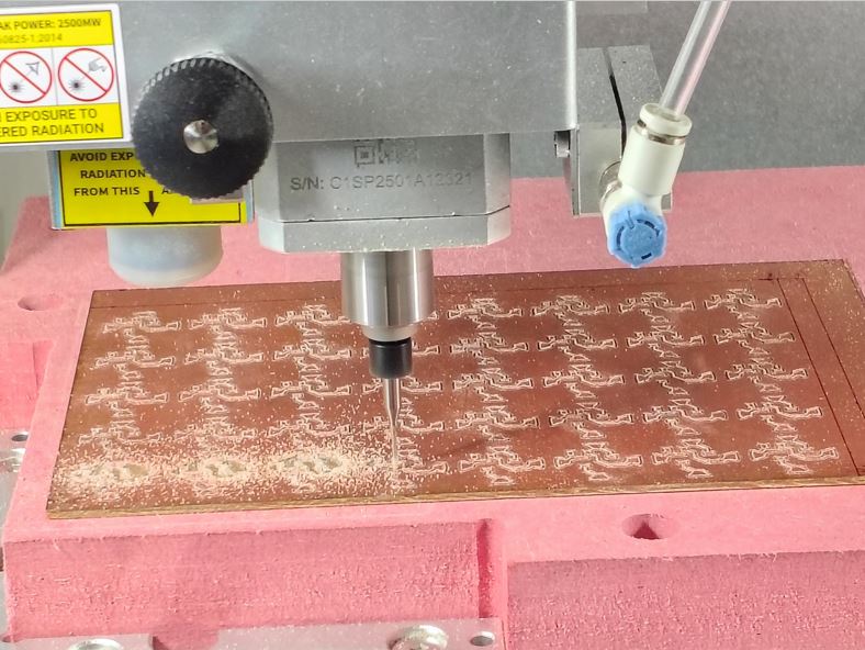
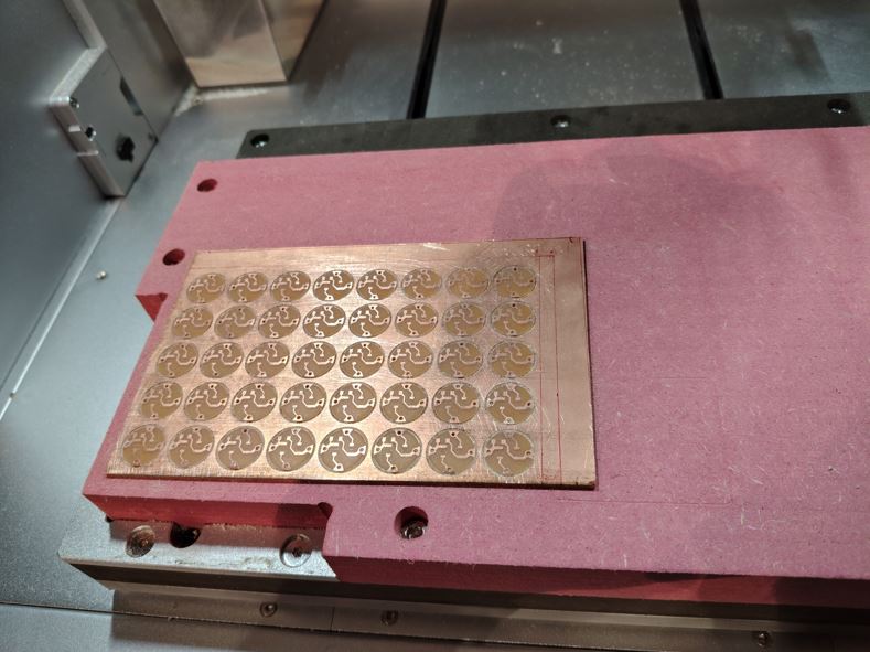
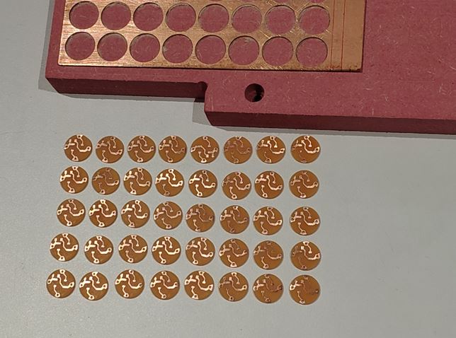
I decided to make Embroidery pixel module in the lab and then use it in the embroidery work. To do this, my instructor suggested to use Carvera PCB Machine because I can multiply the modules in the gerber to PNG layout and then mass-produce it with less wastage.
Digital Fabrication Process : KiCAD PCB Design --> Gerber to PNG (Layout for 40 Modules)--> Mods CE (Generate G-Code) --> Carvera Controller --> PCB Milling --> Soldering --> Testing on Jig --> Done!
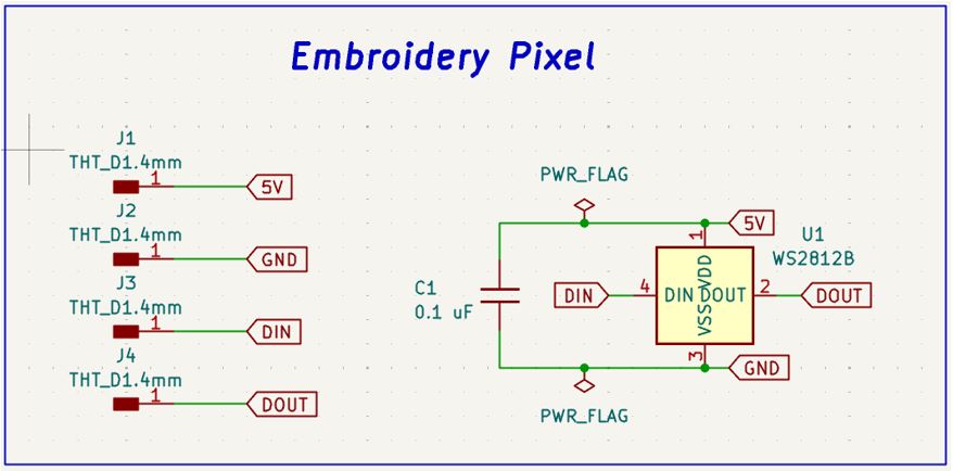
KiCad PCB Design
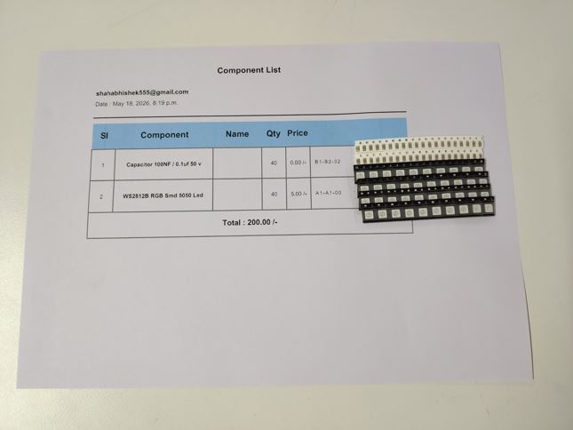
First, I made the schematic design with WS2812B and used 0.1 uF capacitor across the positive and negative act as local energy storage.
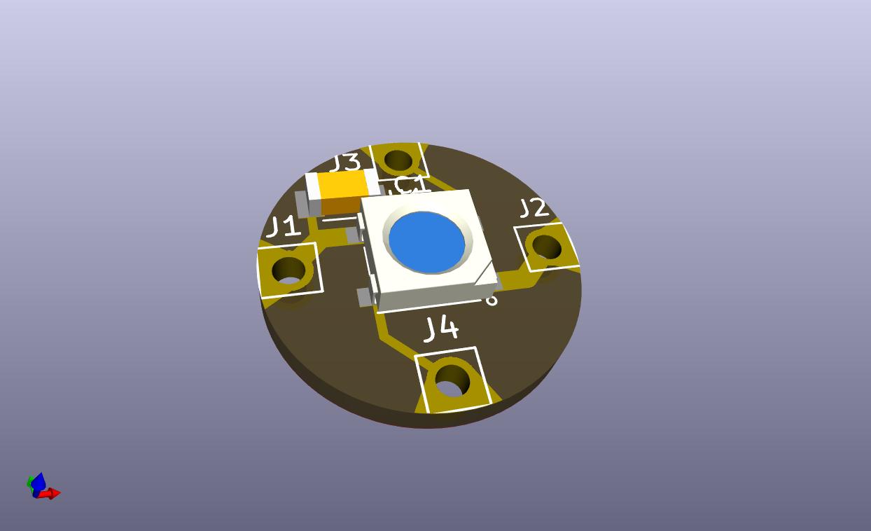
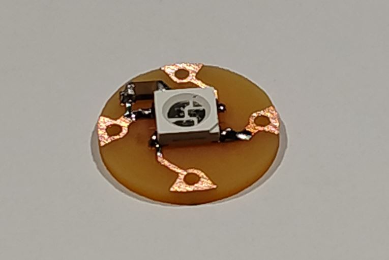
Gerber to PNG (Layout for 40 Modules)
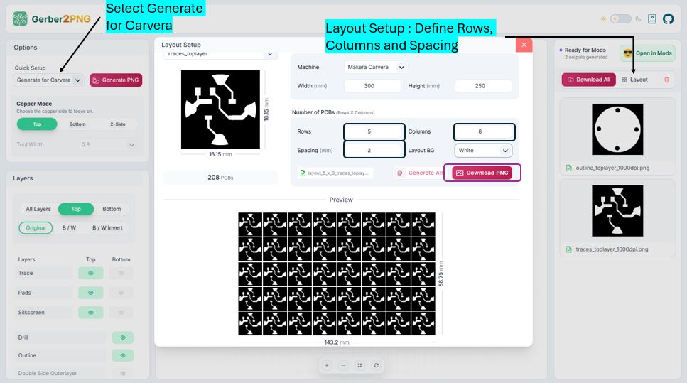
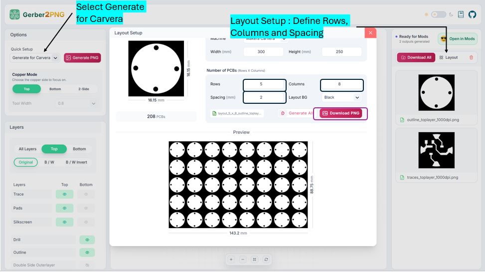
I used Layout option in Gerber2PNG to generate Layout for milling 40 Modules. As si was going to use Carvera Machine, I selected Generate for Carvera and then in Layout Setup, I entered 5 rows and 8 columns and downloaded the PNG. This steps need to be done for both TraceLayer and DrillLayer.
Mods CE (Generate G-COde)
Now, we need to open these PNG files of TraceLayer and DrillLayer into ModsCE to generate the G-code/Tool path for Carvera Machine.
When we start mods and load Carvera the default values are different . But after opening mods and clicking " load file " from the left side bar I added below file which will setup the defaults values that fits our machine, so that's e don't have to change it every time. CarveraMODSSV4.4.json
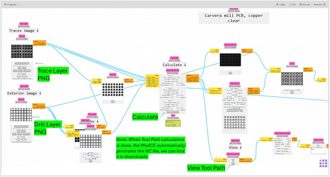
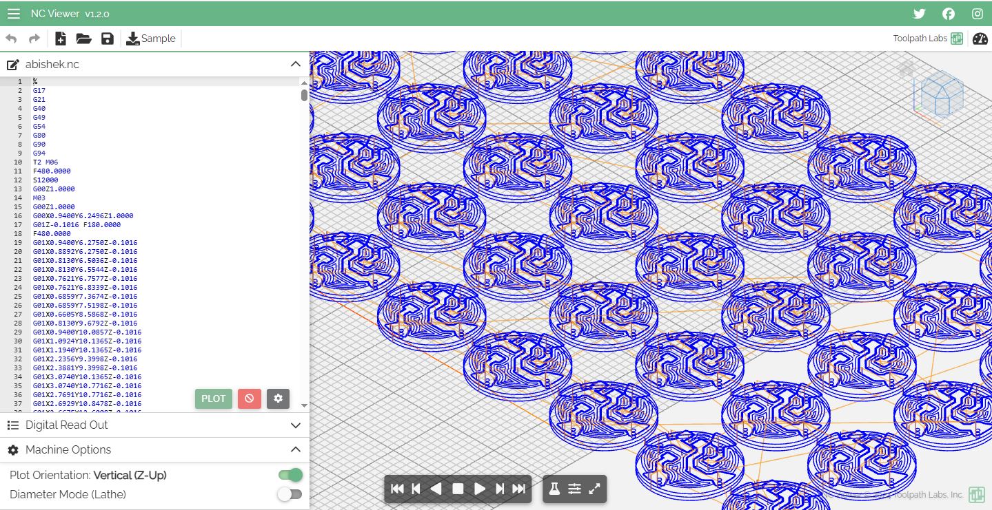
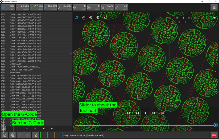
We can verify the Tool path using online NC Viewer or also in CARVERA CONTROLLER Software.
Carvera Controller
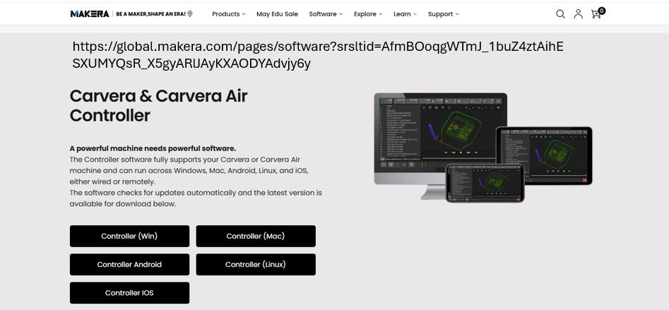
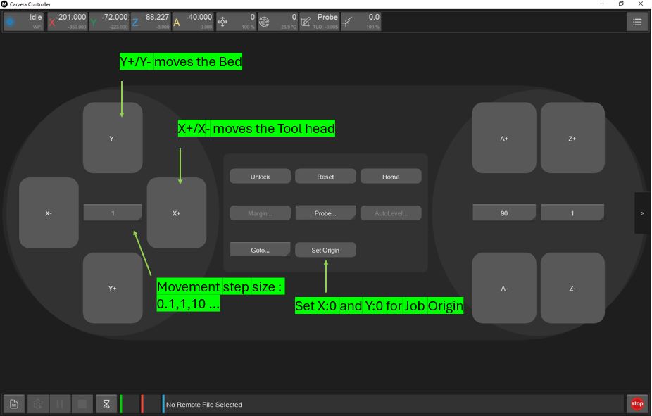
Carvera Controller Tool that we can install and use to connect with Carvera Machine wirelessly via wifi. The tool can be downloaded for here --> Carvera & Carvera Air Controller.
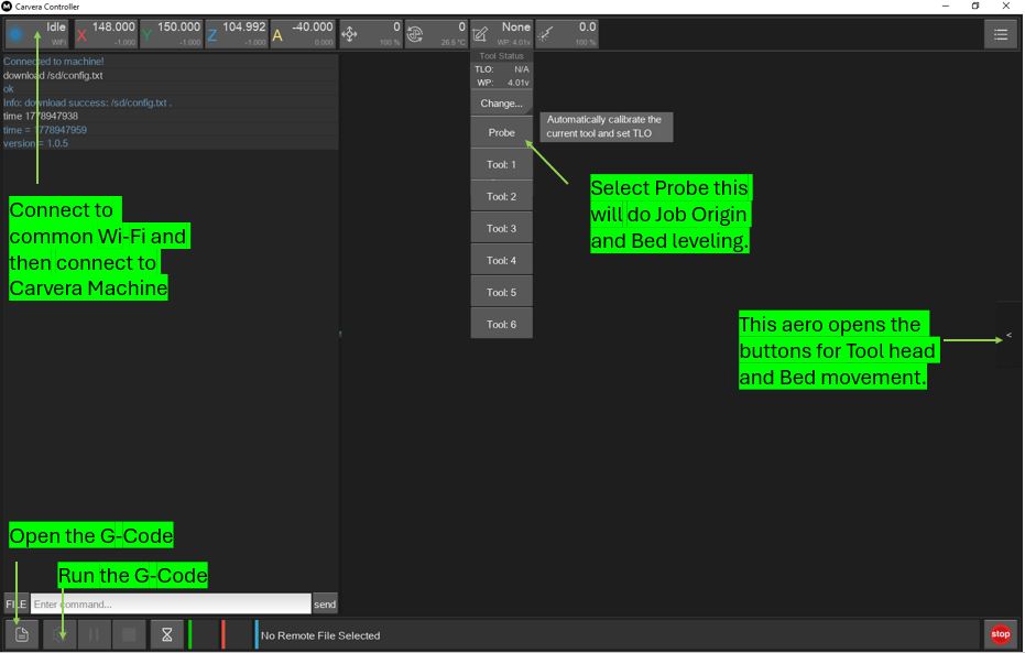
Below is its home screen and follow below Steps for setup.
- Step 1: Connect to wifi by clicking on "NA" button
- Step 2: Click "None" button and Select "Prob" : the machine will begin do Automatic calibration.
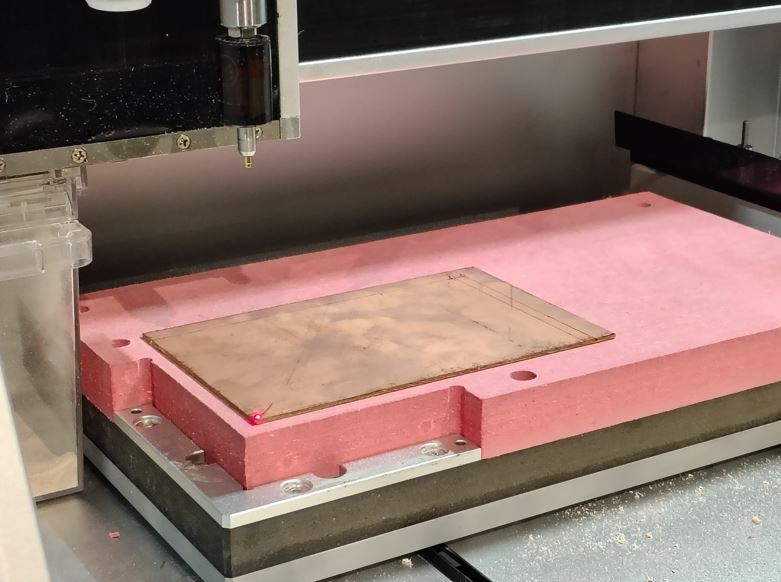
- Step 3: Click "Side Aero" button, a new screen will slide from the right, set the job origin using x+/x- and y+/y- buttons.
- Step 3: Click "Side Aero" button, a new screen will slide from the right, set the job origin using x+/x- and y+/y- buttons.
- Step 4: Click "Set Origin" Enter X-offset:0 and Y-offset:0, select "current pos"
- Step 5: Click "Config and Run" select Auto leveling enter x-points and y-points.
- Step 6: Click "Open" in the left bottom and open the G-code file.
- Step 7: Click "Upload & Select" and then "Run"
PCB Module Milling
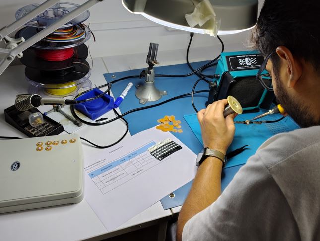
PCB Module Soldering
Design Files Download Links
- Embroidery 2D Design Files : Download here
- Embroidery Machine Execution (.pes) Files : Download here
- Fabric Outline Fusion File : Download here
- DXF File Fabric Outline for Zund Cutting : Download here
- Embroidery Neopixels KiCad Design Files : Download here
- Embroidery Neopixels Gerber Files : Download here
- Embroidery Neopixels Gerber2PNG (40 modules) Files : Download here
Useful Files
- Carvera Mods Setup (.json) File : Download here