Week 6 – Electronics Design
Welcome to the tiny universe where copper traces behave like city roads and electrons commute at the speed of light.
The objective is to understand the basics of electronics components, simulate the circuits, and design a PCB. And hands-on with test equipments for circuit debugging.

AI prompt ChatGPT: "can you give a photo for this : Welcome to the tiny universe where copper traces behave like city roads and electrons commute at the speed of light."
Assignment Overview
- Use the test equipment in your lab to observe the operation of an embedded microcontroller
- Use the test equipment in your lab to observe the operation of a microcontroller circuit board (as a minimum, you should demonstrate the use of a logic analyzer)
- Document your work on the group work page and reflect what you learned on your individual page
- Use an EDA tool to design an embedded microcontroller system using parts from the inventory, and check its design rules for fabrication.
- Extra credit: Simulate a circuit.
- Extra credit: try another design workflow.
- Extra credit: design a case.
Group Assignment
In this group assignment, we used different test instruments to understand how a microcontroller circuit works. First, we used a multimeter and understand it various modes and measurement functions. Next, we used the DC supply to generate DC voltage it has Voltage set point and Current set point limits, which is very useful in protecting our circuit board from damage due to internal short circuits. Next, we used an oscilloscope to observe the clock signals, the oscilloscope has default square wave of 50% duty cycle generation pins that we can use to tune voltage prob and set the voltage prob's gain factor. Finally, we gave reverse voltage to electrolytic capacitor and observed the blast.
Group Assignment : Link| Instrument | Function |
|---|---|
| Multimeter | Measures electrical properties (voltage, current, and resistance) and tests components (diodes, continuity). |
| Oscilloscope | Visualizes and analyzes electrical waveforms (voltage vs. time) for signal integrity and timing. |
| Function Generator | Generates test signals (sine, square, and triangle waves) to simulate inputs for circuit testing. |
| Bench Power Supply | Provides stable, adjustable DC power with voltage and current control for prototyping and testing. |
| Logic Analyzer | Captures and analyzes digital signals (timing and communication protocols) for debugging digital and embedded systems. |
Key Learnings
- Troubleshooting Circuits – Use a Multimeter and Oscilloscope.
- Signal Simulation and Analysis – Use a Function Generator and Oscilloscope.
- Powering PCB/Electronics – Use a Bench Power Supply.
- Digital System Debugging – Use a Logic Analyzer.
- Component Validation – Use a Multimeter and Oscilloscope.
- Logic analyzers are essential tools for debugging and understanding communication protocols.
- Multiple communication protocols such as UART, I²C, and SPI can be captured and analyzed simultaneously.
- Timing information plays a critical role in troubleshooting embedded systems and identifying communication issues.
- Automatic protocol decoding significantly reduces debugging time compared to manually interpreting individual bits.
- Understanding communication buses and protocols is a fundamental skill for embedded system development.
Simulate a circuit
WOKWI
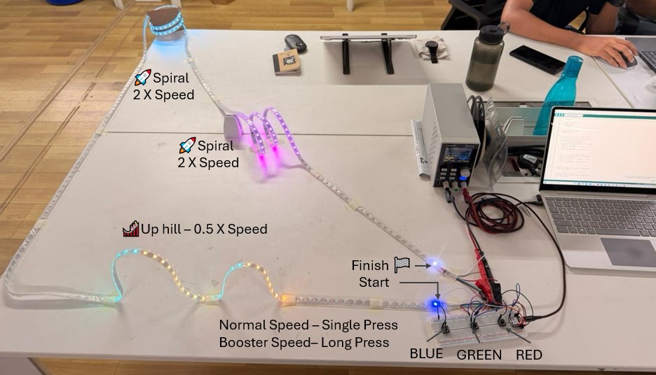
I explored WOKWI to simulate a circuit. We were given a task to simulate the hardest circuit that I programmed during the Embedded Programming week. The hardest circuit that programmed was LED Racer, so I tried simulating that in WOKWI. It is an online electronics simulator where I can design and test circuits directly in my browser. We can simulate development boards [such as XIAO, ESP32, Arduino, Raspberry Pi Pico] along with inputs [Push Button, Sensors], outputs [LEDs, Displays] and communication [I2C, SPI, Serial communication] between them. Its advantages are we can test before building, debug easily and no Hardware required. However, it has limitations that it simulates the logic and code but not the physical reality such as current flow, noises-voltage deep, decoupling capacitor effect and power side issues.
Open the WOKWI from here wokwi.com. The workflow is Open WOKWI >> select development board >> Select an example template >> Start editing in simulator. Note that WOKWi supports both Arduino Style Programming and also MicroPython. I selected XIAO ESP32S3 and Traffic control template to further edit them and develop my hardest circuit from Embedded Programming Week.
Connection Details: First, I added three push buttons and I connected the Red, Green and Blue push buttons to D0, D1 and D3 respectively. Then, I added WS2812B LED Strip and connect its DIN pin to D6 Pin of XIAO and Supply and GND pin to 5V PIN and GND of XIAO board. Next, Important thing is to add the required Libraries under Library Manager tab, I added FastLED and other Libraries which I already had in my Arduino environment to avoid any errors.
Note that sometimes it takes very longer time to simulate it on its server, to locally simulate it we can use VC code environment the guide for setting the tool chain is explained here Wokwi for VS Code.
// ═══════════════════════════════════════════════════════
//   3-PLAYER LED RACING GAME - XIAO RP2040
//   Track: 5m WS2812B Strip (300 LEDs)
//
//   PLAYER 1 (RED):   Forward D0, Booster D1
//   PLAYER 2 (GREEN): Forward D2, Booster D3
//   PLAYER 3 (BLUE):  Forward D4, Booster D5
// ═══════════════════════════════════════════════════════

#include

// ── LED Strip Configuration ─────────────────────────────
#define LED_PIN     D6          // Data pin to LED strip
#define NUM_LEDS    300         // 5 meters × 60 LEDs/meter = 300 LEDs
#define LED_TYPE    WS2812B
#define COLOR_ORDER GRB
#define BRIGHTNESS  100

CRGB leds[NUM_LEDS];

// ── Player Button Pins ──────────────────────────────────
// Player 1 - RED
#define P1_FORWARD_PIN  D0

// Player 2 - GREEN
#define P2_FORWARD_PIN  D1

// Player 3 - BLUE
#define P3_FORWARD_PIN  D2

// ── Game Variables ──────────────────────────────────────
struct Player {
  int position;              // Current LED position (0-299)
  CRGB color;               // Player color
  int forwardPin;           // Forward button pin
  String name;              // Player name
  bool finished;            // Has player finished?
  unsigned long finishTime; // Time when finished
  int boostsRemaining;      // Number of boosts left

  // Long press detection
  bool buttonPressed;       // Current button state
  unsigned long pressStartTime; // When button was pressed
  bool moveExecuted;        // Has move been executed for this press
};

Player players[3];
unsigned long gameStartTime = 0;
bool gameStarted = false;
bool gameOver = false;
int finishOrder = 0;

// Game settings
#define NORMAL_SPEED      4     // LEDs to move per forward press
#define BOOSTED_SPEED     25     // LEDs to move with booster active
#define MAX_BOOSTS        2    // Maximum number of boosts per player
#define LONG_PRESS_TIME   500   // Hold button for 500ms to activate boost
#define DEBOUNCE_DELAY    50    // Debounce time in ms
#define FINISH_LINE       (NUM_LEDS - 1)  // Position 299
#define TRAIL_LENGTH      4    // Length of LED trail behind player

// ── Track Features with Speed Modifiers ─────────────────
// Hill 1: LEDs 17-31 (split into up and down)
#define HILL1_START       17
#define HILL1_PEAK        24    // Middle of hill (17+31)/2 = 24
#define HILL1_END         31
#define HILL1_UP_SPEED    0.5   // Slow uphill
#define HILL1_DOWN_SPEED  2.0   // Fast downhill!

// Hill 2: LEDs 33-54 (split into up and down)
#define HILL2_START       33
#define HILL2_PEAK        43    // Middle of hill (33+54)/2 ≈ 43
#define HILL2_END         54
#define HILL2_UP_SPEED    0.5   // Slow uphill
#define HILL2_DOWN_SPEED  2.0   // Fast downhill!

// Horizontal Spiral: LEDs 127-183 (FAST - gravity assists!)
#define SPIRAL1_START     127
#define SPIRAL1_END       183
#define SPIRAL1_SPEED     2.0   // Double speed in spiral!

// Vertical Spiral: LEDs 223-273 (VERY FAST - falling down!)
#define SPIRAL2_START     223
#define SPIRAL2_END       273
#define SPIRAL2_SPEED     3.0   // Triple speed in vertical spiral!

// ════════════════════════════════════════════════════════
void setup() {
  Serial.begin(115200);
  delay(1000);

  // Initialize FastLED
  FastLED.addLeds(leds, NUM_LEDS);
  FastLED.setBrightness(BRIGHTNESS);
  FastLED.clear();
  FastLED.show();

  // Initialize Player 1 - RED
  players[0].position = 0;
  players[0].color = CRGB::Red;
  players[0].forwardPin = P1_FORWARD_PIN;
  players[0].name = "RED";
  players[0].finished = false;
  players[0].boostsRemaining = MAX_BOOSTS;
  players[0].buttonPressed = false;
  players[0].pressStartTime = 0;
  players[0].moveExecuted = false;

  // Initialize Player 2 - GREEN
  players[1].position = 0;
  players[1].color = CRGB::Green;
  players[1].forwardPin = P2_FORWARD_PIN;
  players[1].name = "GREEN";
  players[1].finished = false;
  players[1].boostsRemaining = MAX_BOOSTS;
  players[1].buttonPressed = false;
  players[1].pressStartTime = 0;
  players[1].moveExecuted = false;

  // Initialize Player 3 - BLUE
  players[2].position = 0;
  players[2].color = CRGB::Blue;
  players[2].forwardPin = P3_FORWARD_PIN;
  players[2].name = "BLUE";
  players[2].finished = false;
  players[2].boostsRemaining = MAX_BOOSTS;
  players[2].buttonPressed = false;
  players[2].pressStartTime = 0;
  players[2].moveExecuted = false;

  // Setup button pins (INPUT_PULLUP = active LOW)
  for(int i = 0; i < 3; i++) {
    pinMode(players[i].forwardPin, INPUT_PULLUP);
  }

  // Welcome message
  Serial.println("╔═══════════════════════════════════════════════════╗");
  Serial.println("║        LED VELOCITY RACE - SPIRAL DASH          ║");
  Serial.println("║           3-Player Racing Game 🏁               ║");
  Serial.println("╚═══════════════════════════════════════════════════╝");
  Serial.println("  Track Length: 300 LEDs (5 meters)");
  Serial.println("──────────────────────────────────────────────────────");
  Serial.println("  PLAYER 1 (RED)   - Button: D0");
  Serial.println("  PLAYER 2 (GREEN) - Button: D1");
  Serial.println("  PLAYER 3 (BLUE)  - Button: D2");
  Serial.println("──────────────────────────────────────────────────────");
  Serial.println("  Quick Press: Move 1 LED forward");
  Serial.println("  Long Press (hold 0.5s): BOOST 5 LEDs forward");
  Serial.println("  Boosts available: " + String(MAX_BOOSTS) + " per player");
  Serial.println("  Total boost distance: " + String(MAX_BOOSTS * BOOSTED_SPEED) + " LEDs");
  Serial.println("──────────────────────────────────────────────────────");
  Serial.println("✓ Press any button to start the race!");
  Serial.println();

  // Show starting line
  showStartingPositions();
}

// ════════════════════════════════════════════════════════
void loop() {
  if(!gameStarted) {
    // Wait for any player to press forward to start
    for(int i = 0; i < 3; i++) {
      if(digitalRead(players[i].forwardPin) == LOW) {
        startGame();
        break;
      }
    }
    return;
  }

  if(gameOver) {
    // Show victory animation
    victoryAnimation();
    return;
  }

  // Read buttons and update player positions
  for(int i = 0; i < 3; i++) {
    if(!players[i].finished) {
      updatePlayer(i);
    }
  }

  // Update LED strip
  displayRace();
  FastLED.show();

  // Check if all players finished
  checkGameOver();
}

// ════════════════════════════════════════════════════════
void startGame() {
  gameStarted = true;
  gameStartTime = millis();

  Serial.println("🏁🏁🏁 RACE STARTED! 🏁🏁🏁");
  Serial.println();
  Serial.println("🎢 TRACK FEATURES:");
  Serial.println("  ⛰️↗ Hill 1 UP (LEDs 17-24): SLOW climb! 0.5x");
  Serial.println("  ⛰️↘ Hill 1 DOWN (LEDs 25-31): FAST descent! 2x");
  Serial.println("  ⛰️↗ Hill 2 UP (LEDs 33-43): SLOW climb! 0.5x");
  Serial.println("  ⛰️↘ Hill 2 DOWN (LEDs 44-54): FAST descent! 2x");
  Serial.println("  🌀 Horizontal Spiral (LEDs 127-183): FAST! 2x speed!");
  Serial.println("  🌪️  Vertical Spiral (LEDs 223-273): SUPER FAST! 3x speed!");
  Serial.println();

  // Countdown animation - flash entire track in white
  for(int i = 3; i > 0; i--) {
    // Light up entire track in white
    fill_solid(leds, NUM_LEDS, CRGB::White);
    FastLED.show();
    Serial.println("  " + String(i) + "...");
    delay(500);

    // Turn off entire track
    FastLED.clear();
    FastLED.show();
    delay(300);
  }

  Serial.println("  GO! 🚀");
  Serial.println();
}

// ════════════════════════════════════════════════════════
// Get speed multiplier based on current position
// ════════════════════════════════════════════════════════
float getSpeedMultiplier(int position) {
  // Hill 1 - Uphill (slow) or Downhill (fast)
  if(position >= HILL1_START && position <= HILL1_END) {
    if(position <= HILL1_PEAK) {
      return HILL1_UP_SPEED;    // Climbing up - slow
    } else {
      return HILL1_DOWN_SPEED;  // Going down - fast!
    }
  }

  // Hill 2 - Uphill (slow) or Downhill (fast)
  if(position >= HILL2_START && position <= HILL2_END) {
    if(position <= HILL2_PEAK) {
      return HILL2_UP_SPEED;    // Climbing up - slow
    } else {
      return HILL2_DOWN_SPEED;  // Going down - fast!
    }
  }

  // Horizontal Spiral - Fast!
  if(position >= SPIRAL1_START && position <= SPIRAL1_END) {
    return SPIRAL1_SPEED;
  }

  // Vertical Spiral - Very Fast!
  if(position >= SPIRAL2_START && position <= SPIRAL2_END) {
    return SPIRAL2_SPEED;
  }

  // Normal track - standard speed
  return 1.0;
}

// ════════════════════════════════════════════════════════
// Get zone name for current position
// ════════════════════════════════════════════════════════
String getZoneName(int position) {
  if(position >= HILL1_START && position <= HILL1_END) {
    if(position <= HILL1_PEAK) {
      return "⛰️↗ HILL 1 UP";
    } else {
      return "⛰️↘ HILL 1 DOWN";
    }
  }
  if(position >= HILL2_START && position <= HILL2_END) {
    if(position <= HILL2_PEAK) {
      return "⛰️↗ HILL 2 UP";
    } else {
      return "⛰️↘ HILL 2 DOWN";
    }
  }
  if(position >= SPIRAL1_START && position <= SPIRAL1_END) {
    return "🌀 SPIRAL";
  }
  if(position >= SPIRAL2_START && position <= SPIRAL2_END) {
    return "🌪️ V-SPIRAL";
  }
  return "";
}

// ════════════════════════════════════════════════════════
void updatePlayer(int playerIndex) {
  Player &p = players[playerIndex];

  bool buttonCurrentlyPressed = (digitalRead(p.forwardPin) == LOW);

  // Button just pressed (transition from not pressed to pressed)
  if(buttonCurrentlyPressed && !p.buttonPressed) {
    p.buttonPressed = true;
    p.pressStartTime = millis();
    p.moveExecuted = false;
  }

  // Button is being held down
  if(buttonCurrentlyPressed && p.buttonPressed && !p.moveExecuted) {
    unsigned long pressDuration = millis() - p.pressStartTime;

    // Long press detected (500ms+) → BOOST!
    if(pressDuration >= LONG_PRESS_TIME) {
      if(p.boostsRemaining > 0) {
        // Get speed multiplier for current position
        float speedMultiplier = getSpeedMultiplier(p.position);

        // Execute boost move with track speed modifier
        int actualMove = round(BOOSTED_SPEED * speedMultiplier);
        p.position += actualMove;
        p.boostsRemaining--;
        p.moveExecuted = true;

        // Cap at finish line
        if(p.position >= FINISH_LINE) {
          p.position = FINISH_LINE;
          playerFinished(playerIndex);
        }

        String zoneName = getZoneName(p.position);
        if(zoneName != "") {
          Serial.println("🚀 " + p.name + " BOOSTED +" + String(actualMove) + " to " +
                        String(p.position) + " " + zoneName + " ⚡ Boosts: " + String(p.boostsRemaining));
        } else {
          Serial.println("🚀 " + p.name + " BOOSTED to position " + String(p.position) +
                        "! ⚡ Boosts left: " + String(p.boostsRemaining));
        }
      } else {
        // No boosts left, do normal move instead
        float speedMultiplier = getSpeedMultiplier(p.position);
        int actualMove = round(NORMAL_SPEED * speedMultiplier);
        p.position += actualMove;
        p.moveExecuted = true;

        if(p.position >= FINISH_LINE) {
          p.position = FINISH_LINE;
          playerFinished(playerIndex);
        }

        Serial.println("→ " + p.name + " moved +" + String(actualMove) + " to " +
                      String(p.position) + " ⚠️ NO BOOSTS LEFT!");
      }
    }
  }

  // Button just released
  if(!buttonCurrentlyPressed && p.buttonPressed) {
    unsigned long pressDuration = millis() - p.pressStartTime;

    // Short press (less than 500ms) → Normal move with speed modifier
    if(pressDuration < LONG_PRESS_TIME && !p.moveExecuted) {
      float speedMultiplier = getSpeedMultiplier(p.position);
      int actualMove = round(NORMAL_SPEED * speedMultiplier);

      p.position += actualMove;

      // Cap at finish line
      if(p.position >= FINISH_LINE) {
        p.position = FINISH_LINE;
        playerFinished(playerIndex);
      }

      String zoneName = getZoneName(p.position);
      if(zoneName != "") {
        Serial.println("→ " + p.name + " moved +" + String(actualMove) + " to " +
                      String(p.position) + " " + zoneName + " ⚡ Boosts: " + String(p.boostsRemaining));
      } else {
        Serial.println("→ " + p.name + " moved to position " + String(p.position) +
                      " ⚡ Boosts: " + String(p.boostsRemaining));
      }
    }

    // Reset button state
    p.buttonPressed = false;
    p.moveExecuted = false;
  }
}

// ════════════════════════════════════════════════════════
void playerFinished(int playerIndex) {
  Player &p = players[playerIndex];

  if(!p.finished) {
    p.finished = true;
    finishOrder++;
    p.finishTime = millis() - gameStartTime;

    Serial.println();
    Serial.println("═══════════════════════════════════════════════════");
    Serial.println("  🏆 " + p.name + " FINISHED in position #" + String(finishOrder) + "!");
    Serial.println("     Time: " + String(p.finishTime / 1000.0, 2) + " seconds");
    Serial.println("═══════════════════════════════════════════════════");
    Serial.println();
  }
}

// ════════════════════════════════════════════════════════
void displayRace() {
  FastLED.clear();

  // Draw finish line (white)
  leds[FINISH_LINE] = CRGB::White;

  // Draw track zone markers (subtle background colors)
  // Hill 1 Uphill - Dark red/brown (climbing is hard!)
  for(int i = HILL1_START; i <= HILL1_PEAK; i++) {
    leds[i] = CRGB(20, 10, 0);
  }
  // Hill 1 Downhill - Green tint (going fast!)
  for(int i = HILL1_PEAK + 1; i <= HILL1_END; i++) {
    leds[i] = CRGB(0, 20, 10);
  }

  // Hill 2 Uphill - Dark red/brown
  for(int i = HILL2_START; i <= HILL2_PEAK; i++) {
    leds[i] = CRGB(20, 10, 0);
  }
  // Hill 2 Downhill - Green tint
  for(int i = HILL2_PEAK + 1; i <= HILL2_END; i++) {
    leds[i] = CRGB(0, 20, 10);
  }

  // Horizontal Spiral - Cyan glow (fast zone!)
  for(int i = SPIRAL1_START; i <= SPIRAL1_END; i++) {
    leds[i] = CRGB(0, 15, 20);
  }

  // Vertical Spiral - Purple glow (super fast zone!)
  for(int i = SPIRAL2_START; i <= SPIRAL2_END; i++) {
    leds[i] = CRGB(20, 0, 20);
  }

  // Draw podium positions at finish line (for finished players)
  int finishPositions[3] = {FINISH_LINE, FINISH_LINE - 1, FINISH_LINE - 2}; // 299, 298, 297
  int finishedPlayersSorted[3] = {-1, -1, -1};
  int finishCount = 0;

  // Sort finished players by finish time
  for(int rank = 0; rank < 3; rank++) {
    unsigned long bestTime = 999999999;
    int bestPlayer = -1;

    for(int p = 0; p < 3; p++) {
      if(players[p].finished) {
        // Check if this player hasn't been placed yet
        bool alreadyPlaced = false;
        for(int r = 0; r < rank; r++) {
          if(finishedPlayersSorted[r] == p) {
            alreadyPlaced = true;
            break;
          }
        }

        if(!alreadyPlaced && players[p].finishTime < bestTime) {
          bestTime = players[p].finishTime;
          bestPlayer = p;
        }
      }
    }

    if(bestPlayer != -1) {
      finishedPlayersSorted[rank] = bestPlayer;
      finishCount++;
    }
  }

  // Display finished players on podium positions
  for(int rank = 0; rank < finishCount; rank++) {
    int playerIndex = finishedPlayersSorted[rank];
    if(playerIndex != -1) {
      leds[finishPositions[rank]] = players[playerIndex].color;
    }
  }

  // Draw each player with a trail
  for(int i = 0; i < 3; i++) {
    Player &p = players[i];

    if(!p.finished) {  // Only draw trail and position for active players
      // Draw trail (fading) - OVERRIDE zone colors completely
      for(int t = 1; t <= TRAIL_LENGTH; t++) {
        int trailPos = p.position - t;
        if(trailPos >= 0 && trailPos < NUM_LEDS) {
          // Fade trail brightness but keep pure color
          CRGB trailColor = p.color;
          trailColor.fadeToBlackBy(t * 20);

          // OVERRIDE zone color completely (not blend)
          leds[trailPos] = trailColor;
        }
      }

      // Draw player position with visual feedback - PURE COLOR
      if(p.position < NUM_LEDS) {
        // Check if button is being held (charging boost)
        if(p.buttonPressed && !p.moveExecuted) {
          unsigned long pressDuration = millis() - p.pressStartTime;

          if(pressDuration < LONG_PRESS_TIME && p.boostsRemaining > 0) {
            // Charging animation - pulse brightness (pure color)
            uint8_t brightness = map(pressDuration, 0, LONG_PRESS_TIME, 50, 255);
            CRGB chargeColor = p.color;
            chargeColor.fadeToBlackBy(255 - brightness);
            leds[p.position] = chargeColor;
          } else if(pressDuration >= LONG_PRESS_TIME && p.boostsRemaining > 0) {
            // Fully charged - rapid white blink
            if(millis() % 100 < 50) {
              leds[p.position] = CRGB::White;
            } else {
              leds[p.position] = p.color;
            }
          } else if(p.boostsRemaining == 0) {
            // No boosts left - slow pulse (pure color)
            if(millis() % 500 < 250) {
              leds[p.position] = p.color;
            } else {
              leds[p.position] = CRGB::Black;
            }
          }
        } else {
          // Normal state - solid bright pure color (OVERRIDE zone)
          leds[p.position] = p.color;
        }
      }
    }
  }
}

// ════════════════════════════════════════════════════════
void showStartingPositions() {
  FastLED.clear();

  // Show all players at starting line
  for(int i = 0; i < 3; i++) {
    leds[0] = leds[0] + players[i].color;  // Blend all colors at start
  }

  // Show finish line
  leds[FINISH_LINE] = CRGB::White;

  FastLED.show();
}

// ════════════════════════════════════════════════════════
void checkGameOver() {
  int finishedCount = 0;
  for(int i = 0; i < 3; i++) {
    if(players[i].finished) finishedCount++;
  }

  if(finishedCount >= 3) {
    gameOver = true;
    delay(1000);
    printFinalResults();
  }
}

// ════════════════════════════════════════════════════════
void printFinalResults() {
  Serial.println();
  Serial.println("╔═══════════════════════════════════════════════════╗");
  Serial.println("║              🏁 RACE COMPLETE! 🏁                ║");
  Serial.println("╚═══════════════════════════════════════════════════╝");
  Serial.println();

  // Sort players by finish order (who finished first)
  Player sortedPlayers[3];
  for(int i = 0; i < 3; i++) {
    sortedPlayers[i] = players[i];
  }

  // Simple bubble sort by finish time
  for(int i = 0; i < 2; i++) {
    for(int j = 0; j < 2 - i; j++) {
      if(sortedPlayers[j].finishTime > sortedPlayers[j+1].finishTime) {
        Player temp = sortedPlayers[j];
        sortedPlayers[j] = sortedPlayers[j+1];
        sortedPlayers[j+1] = temp;
      }
    }
  }

  // Display podium
  Serial.println("  🥇 1st Place: " + sortedPlayers[0].name + " - " +
                String(sortedPlayers[0].finishTime / 1000.0, 2) + "s");
  Serial.println("     Boosts used: " + String(MAX_BOOSTS - sortedPlayers[0].boostsRemaining) + "/" + String(MAX_BOOSTS));
  Serial.println();
  Serial.println("  🥈 2nd Place: " + sortedPlayers[1].name + " - " +
                String(sortedPlayers[1].finishTime / 1000.0, 2) + "s");
  Serial.println("     Boosts used: " + String(MAX_BOOSTS - sortedPlayers[1].boostsRemaining) + "/" + String(MAX_BOOSTS));
  Serial.println();
  Serial.println("  🥉 3rd Place: " + sortedPlayers[2].name + " - " +
                String(sortedPlayers[2].finishTime / 1000.0, 2) + "s");
  Serial.println("     Boosts used: " + String(MAX_BOOSTS - sortedPlayers[2].boostsRemaining) + "/" + String(MAX_BOOSTS));
  Serial.println();
  Serial.println("──────────────────────────────────────────────────────");
  Serial.println("  Press RESET to play again!");
  Serial.println("══════════════════════════════════════════════════════");
}

// ════════════════════════════════════════════════════════
void victoryAnimation() {
  static uint8_t hue = 0;

  // Rainbow wave celebration
  for(int i = 0; i < NUM_LEDS; i++) {
    leds[i] = CHSV(hue + (i * 255 / NUM_LEDS), 255, 255);
  }

  hue += 3;
  FastLED.show();
  delay(20);
}
Designing in KiCad
KiCad Software setup
KiCad, an Electronic Design Automation (EDA) tool, is a free open-source software use for creating schematics diagram, and printed Circuit Board Layout. The KiCad has an integrated environment of making schematics diagram using component symbol library, then convert schematics into a PCB layout and further convert into Gerber file for PCB manufacturing. The tools exists within the KiCad to create bill of material, 3D model of PCB and Gerber file. First, I downloaded the installation file the KiCad for kicad.org/download/ and installed it.
Create New project
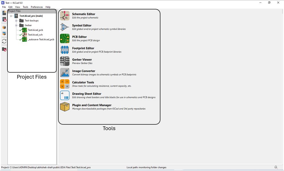
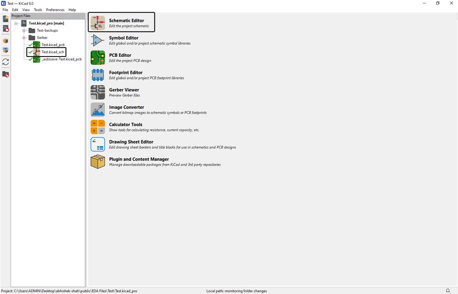
The first window of key looks like below, what we see on right hand side is Tools such as schematics editor, PCB editor, Gerber viewer etc. and on then left hand side is Project file column where we can see the current project file that is been opened. We can create new project file from File >> New Project >> File Name >> Save and give the location where you wish to store the new project file.
Installation Fab library
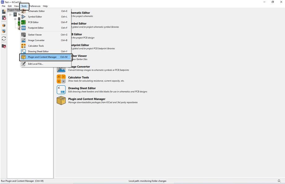
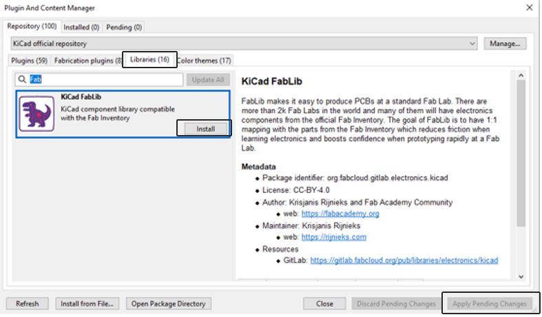
Next step is to install Plugin of KiCad FabLib. It is the Fablab library of standard/official Fablab inventory. Thus, using this library is makes PCB manufacturing easy inside Fablab, there are thousands of Fablab across the world whish manages and uses components from official Fab inventory. This library reduces friction and enables rapid prototyping at Fablab. This to Install the KiCad FabLib click on Tools >> Plugin and Content Manager >> Select the "Libraries" >> click Install >> click "Apply Pending Changes" or alternatively you can also follow the installation steps given at the installation and fab library link.
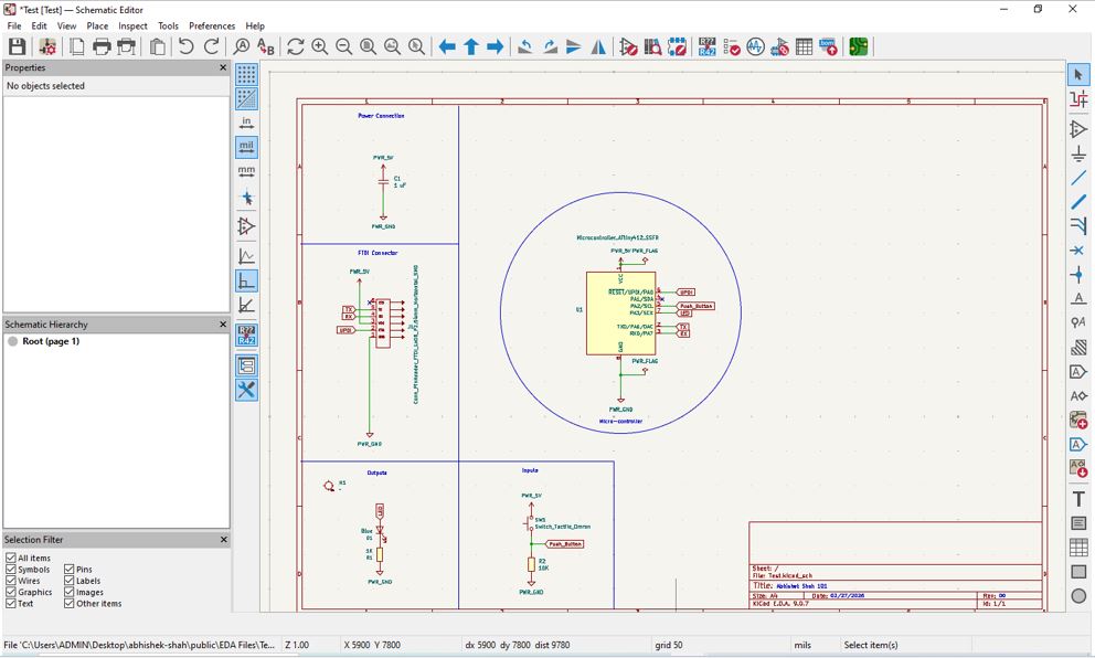
Schematic Design
After installation, we can start schematic designing. In the class, we decided to design a simple blink PCB using ATtiny412 and a push button as input and LED as output. Click on the .kicad_sch file under the mane project file or click on the schematic Editor to Create or Edit the project schematics.
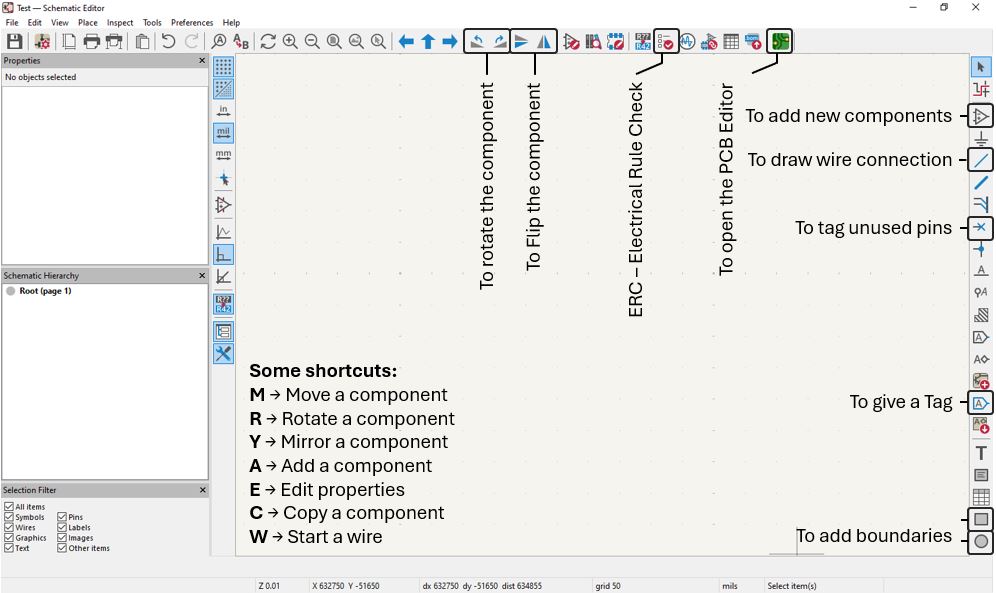
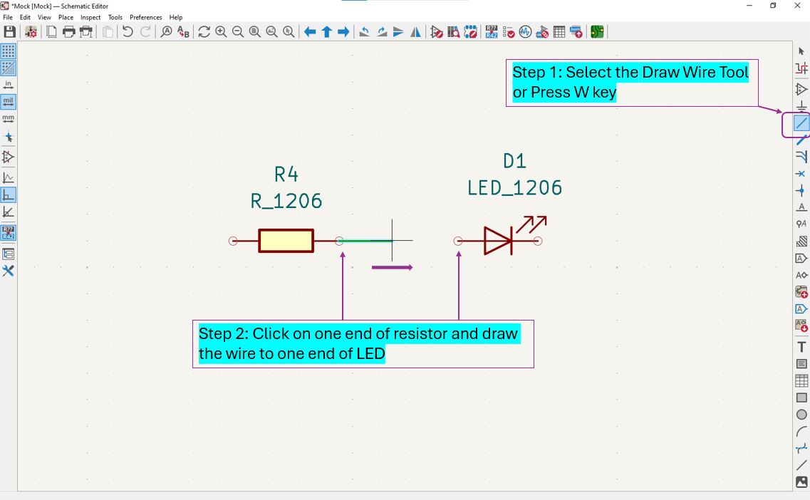
The Project Schematic Editor has multiple icons from which below are very useful and most important once such as add new component opens Component Library, we can chose and add component to schematic. Using Rotate function we can rotate the component in any direction that is more suitable for its connection to other component or controller pin. Using Mirror function we can flip the component's label and value according available space around the component. The Wire Connection is use to draw wire line or connect two components or junctions with the wires. The Tag tool is very useful tool connect two or more points or junctions without drawing wire between them. The Unused Pins are tagged using "X" that indicates that they are not connected anywhere in the circuit. The Boundaries are use to draw a border and divide / organize the schematics into inputs, outputs, power supply, and main controller divisions. The ERC - Electrical Rule Check function is clicked at the to ensure that our schematic is made accordance to the KiCad Rules and to check if it is ready to be open in PCB Editor.
Adding a Symbol
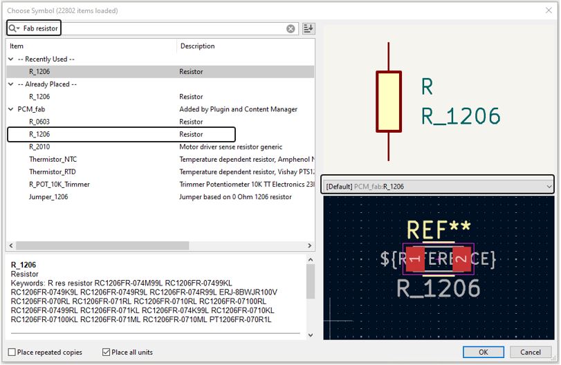
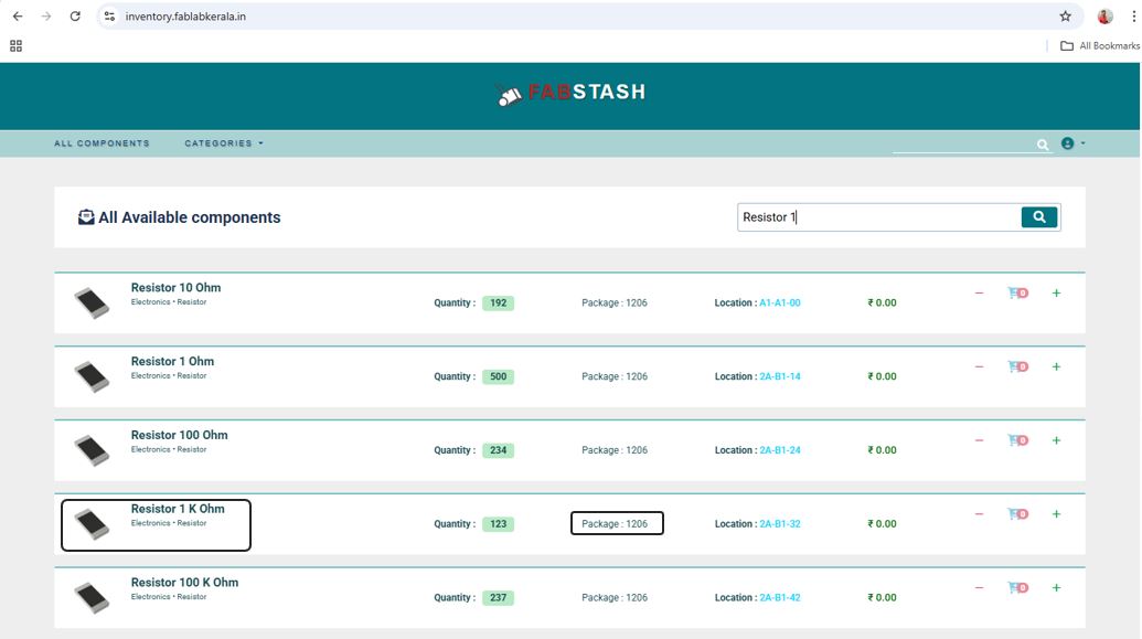
Using above tools, we made a schematic of a simple blink PCB using ATtiny412 and a push button as input and LED as output. I included a current limiting resistor fo value 1k in series with an LED, also a 1 uF capacitor near VCC pin of ATtiny412 as Decoupling Capacitor. The FTDI Horizontal connecter is added to connect with the programmer board. Choosing and adding symbol is an easy step first click on component library >> Search "Fab resistor" >> Select R_1206 under PCM_fab, adding Fab is very important because it will also search the resister inside FabLib and by default select FabLib Footprint. To know whether the component is available in our lab or not out instructor gave a inventory website inventory.fablabkerala.in of FABLAB Kerala
It is very important to check the component availability in the lab and what is its Footprint or Packaging size while doing the circuit designing by referring to inventory website inventory.fablabkerala.in of FABLAB Kerala.
ATtiny412 Pin Details
I referred below pinout details of ATtiny412 from its microchip Datasheets.
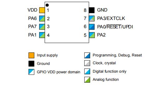
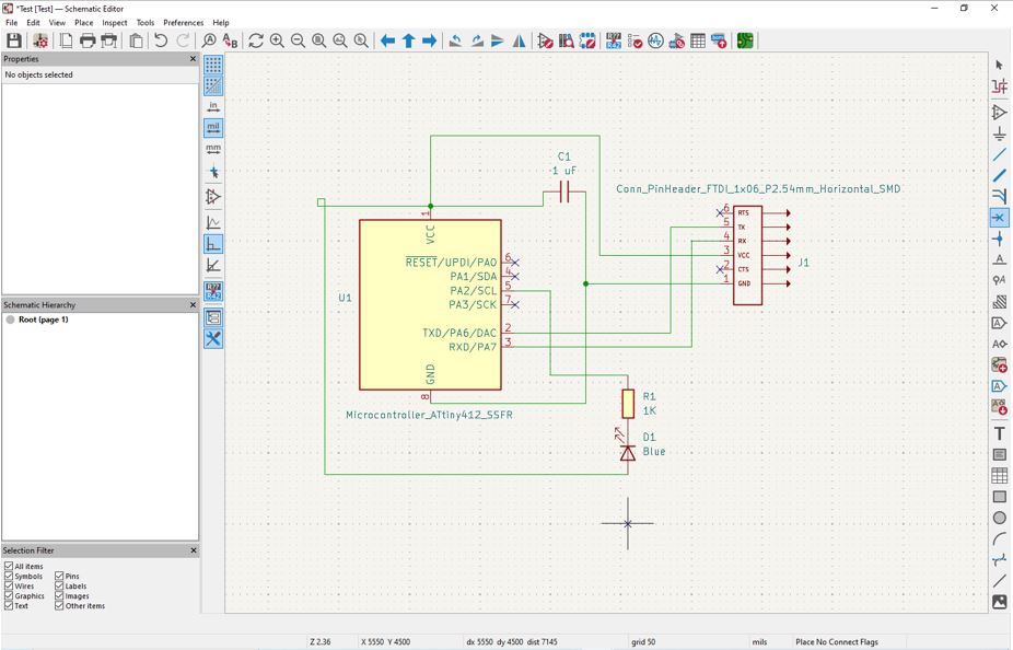
According to the above explanation for resistor and referring to above ATtiny412 Pin Details, I added components [resistors 1k, capacitor 1 uF, LED, and FTDI connector] from the FAb library and connected them using draw wire function. Established connection between components and ATtiny412 MCU.
Example calculation of LED current limiting resistor : In general, LEDs have maximum current carrying capacity of 20mA and depending on micro-controller operating voltage, whether it is 5V or 3V3, we can calculate resistor value.
| Operating Voltage | Calculation | Calculated Resistance | Recommended Resistor |
|---|---|---|---|
| 5 V | R = 5V ÷ 20mA | 250 Ω | Use the nearest standard resistor value available in the lab (e.g., 270 Ω) or higher. |
| 3.3 V | R = 3.3V ÷ 20mA | 165 Ω | Use the nearest standard resistor value available in the lab (e.g., 180 Ω) or higher. |
Adding Global Label
Then our instructor shown us the usefulness of the Tag function. Using tag function we can eliminate the wire make schematic look more intuitive and easy to understand. So for example, here ATtiny412 pin PA2 is connected to anode of the LED via LED Tag, this means even though there is not wire connection but they are connected electrically. By using Flip function we cna flip the connection of two selected tags this is called Flip Tags.
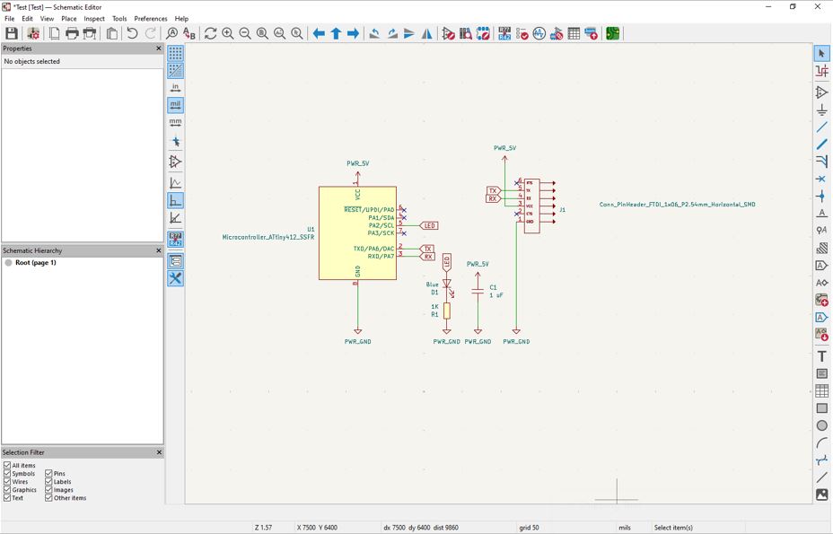
Organizing the Schematics
By using Boundary function we can organize the schematics into different blocks, I made the schematic even more organizes into inputs block, outputs block, power supply block, FTDI Connectorand controller block.
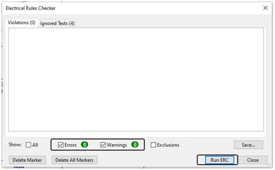
ERC - Electric rule check
Now it is very important step of checking ERC (Electrical Rules), ERC analyzes your schematic and looks for electrical mistakes before I move to PCB layout. ERC checks missing power flags, unconnected pins, etc. If there are not rules violated then it will show zero Errors and if there is any electrical mistake then it will show related Errors and Warnings.
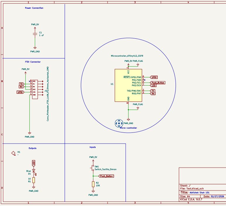
Final Schematics
To get clear view of blocks and schematics details - I have magnified and show the area where schematics is drawn, I have cut the left blank are for better view right schematic.
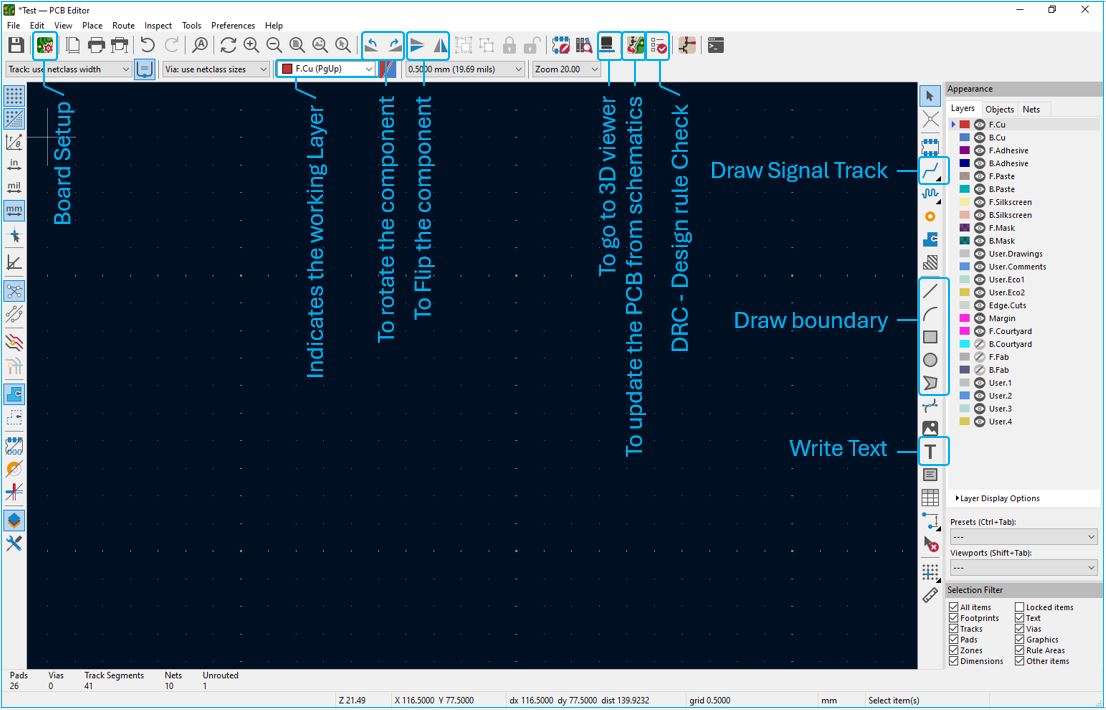
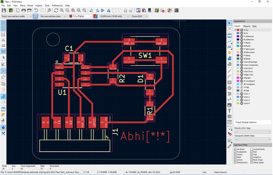
PCB Layout
Now, we need to design PCB for that click on PCB editor icon on schematic window, which will PCB Editor in a new window. The PCB Editor has many function from which the important once are highlighted below. Lets start for Update PCB, if we go back and do any changes in schematics then we need to again do ERC and then comeback to PCB Editor and click on Update PCB function, this will update all the changes done on schematics to PCB Editor. The DRC - Design Rule Check DRC analyzes your PCB layout and checks whether it follows the manufacturing and electrical spacing rules. The DRC checks Clearance violations, Track width, Short circuits, Unconnected nets etc. ERC protects - logic. DRC protects - copper. The Route Track is use for drawing the signal tracks. The Boundary functions are use to create border line once the PCB design is done, this is drawn on the Edge.Cuts layer, to indicate the border or boundary of our PCB to cut during manufacturing. Teh Draw Text function is use to add name to small text to the PCB which is written on Edge.Cuts layer. The Board Setup is very important function, it is use to set parameters related to Copper and Hole of the PCB. The Mirror and Rotate functions almost similar to that of schematics editor, the mirror function flips the component and rotate function revolves the component. In the 3D Viewer we can view our final designed PCB.
Updating and Arranging the components from schematic to PCB editor
We can click on the icon highlighted in below image to update the components from schematics to PCB Editor. Even if, we go back to schematic and add new components or draw new connection, we cna come back to PCB editor and click on Update Component icon to update the PCB Editor.
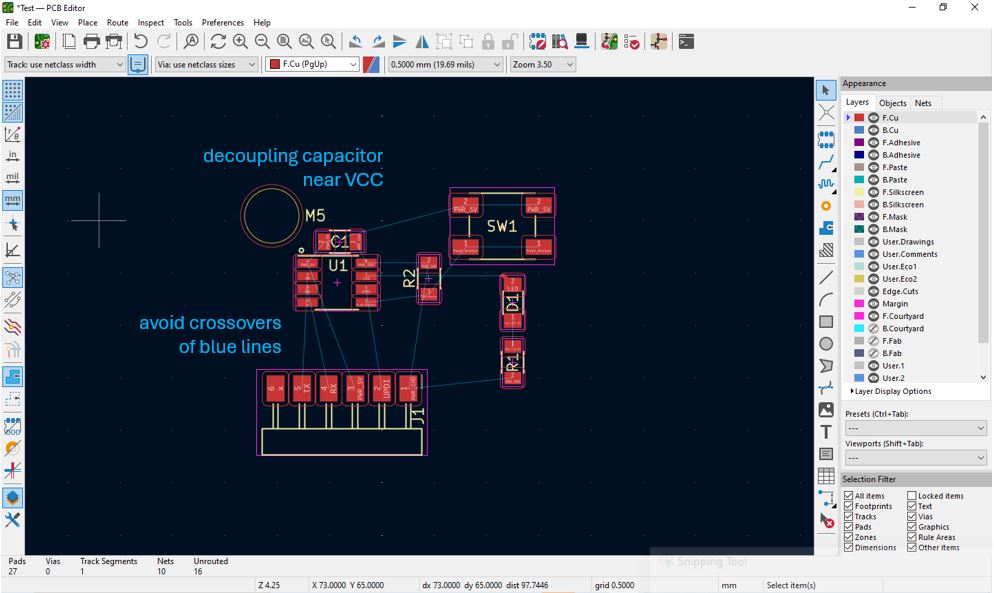
At first the PCB Editor will show footprints and blue lines connecting component footprints. Now, we need to re-arrange the components such that we avoid all crossovers of blue lines to do this we can move the components, rotate the components and flip the component until we see the clear straighten connections or minimal crossover of blue lines. Another important thing is to place the decoupling capacitor near to VCC pin of ATtiny412.
Design Rule setup / Board setup
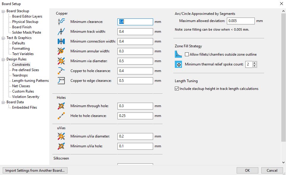
Now make sure that the copper and hole parameter in the Board Setup are according to manufacturing feasibility of our lab. Go to Board Setup >> Design Rules >> Constrains, configure Minimum clearance: 0.4 mm, Minimum track width: 0.4 mm, Minimum connection width: 0.4 mm, Minimum annular width: 0.3 mm, Minimum via diameter: 0.5 mm, Copper to hole clearance: 0.4 mm, Copper to edge clearance: 0.5 mm, Minimum through hole: 0.3 mm and Hole to hole clearance: 0.25 mm.
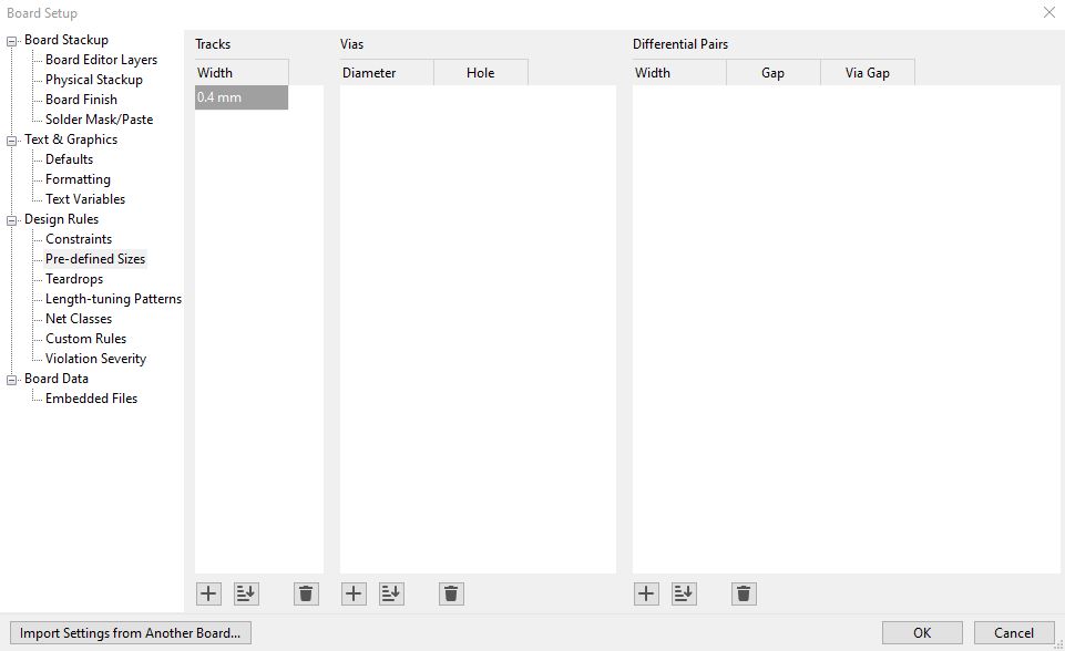
Similarly, go to Board Setup >> Design Rules >> Pre-define Sizes and make sure track width is 0.4 mm.
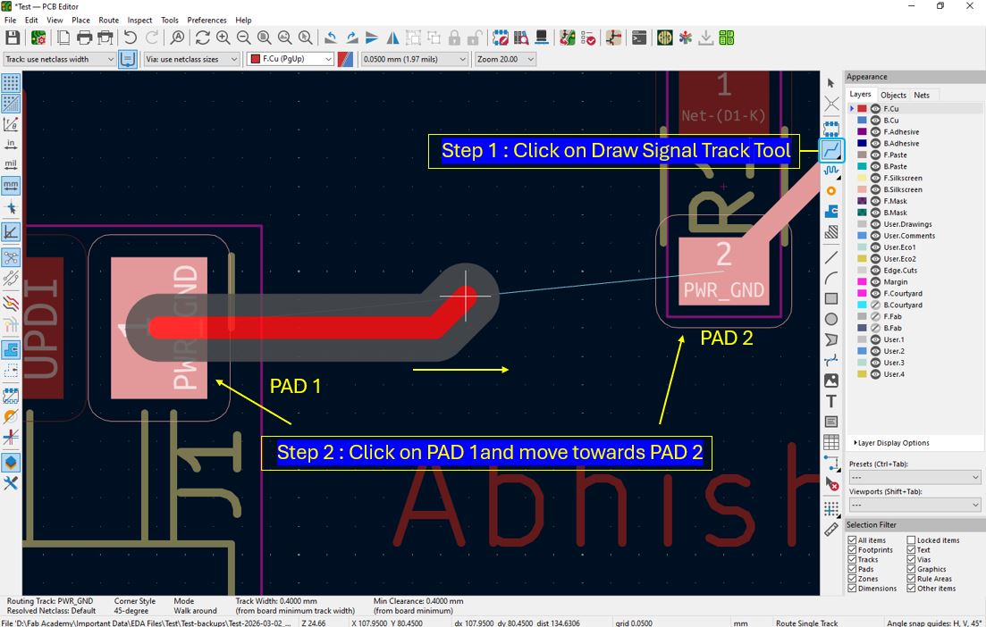
Drawing a wire/track between pads
Use Route Signal Track to draw connection between components, once the connection is done the blue line will disappear. We can click on a track element press U key, this will select entire track. Avoid 90 ° turns and provide Two 45° bends.
Edge cut drawing
Use Boundary function to draw border, this has to be on Edge.cuts layer, we can also give edge radius to the boundary, we can do this by Select boundary >> Right click >> Shape modification >> Fillet lines or Chamfer lines.
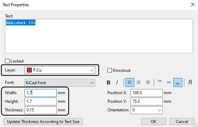
Adding name and graphics on top layer
We can also add Text by using Draw Text function, make sure the layer is F.Cu front copper layer and font width and hight are 1.7 mm and thickness 0.15 mm.
DRC check / Design Rule check
Finally, we need to perform DRC - Design Rul Check, for my design it gave below error Annular width (board setup constraints min annular width 0.3 mm: actual 0.1mm), PTH pad [
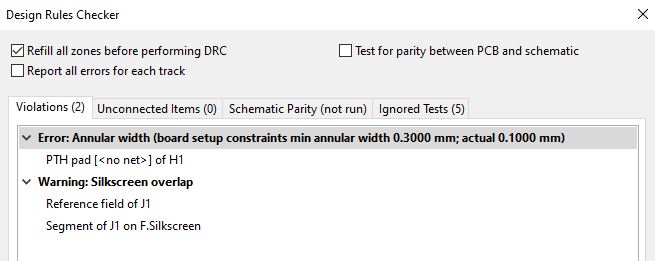
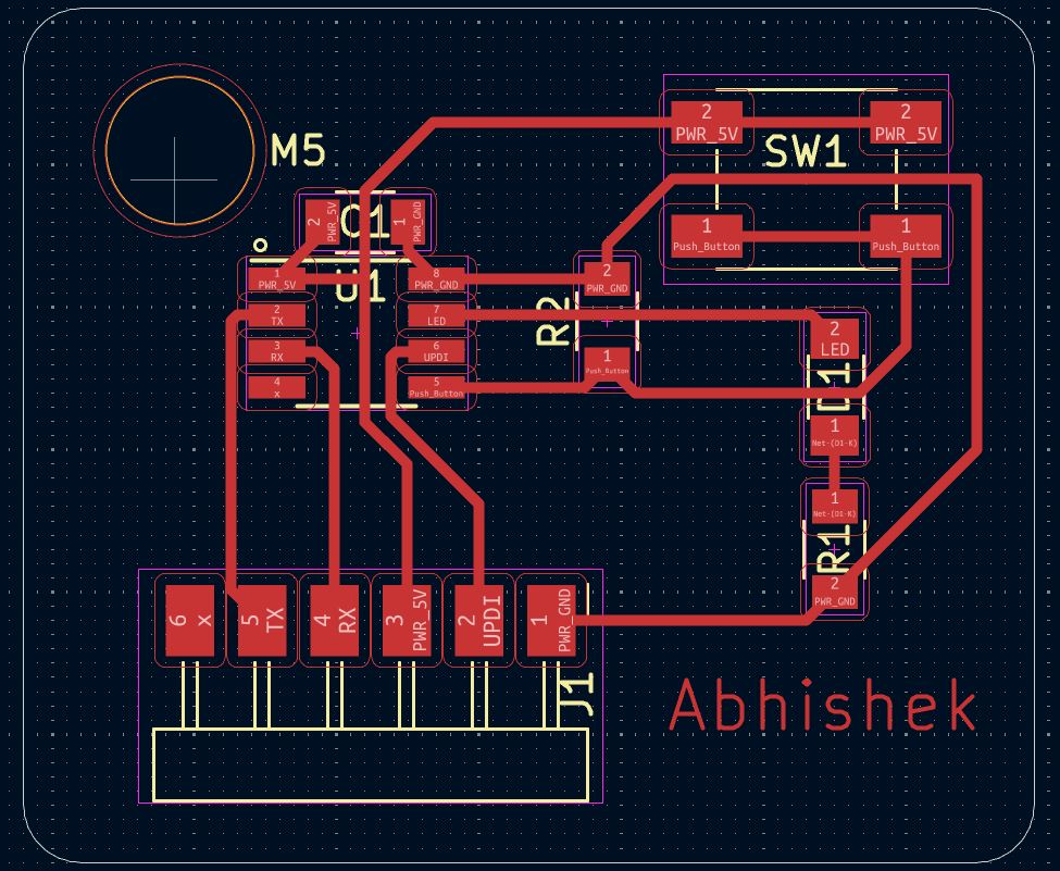
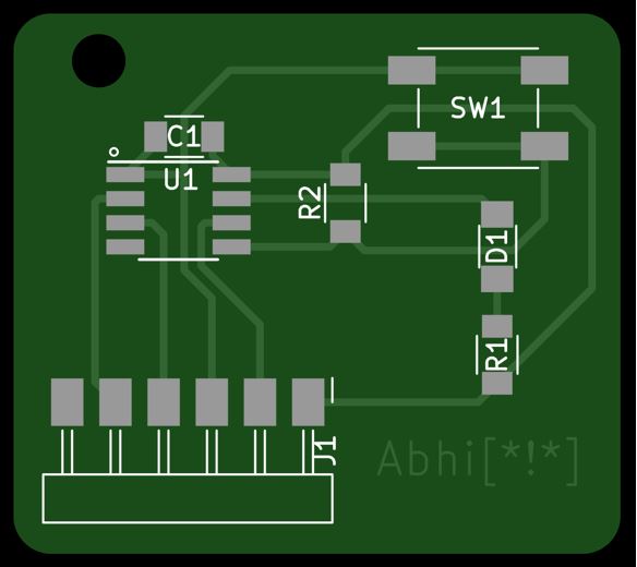
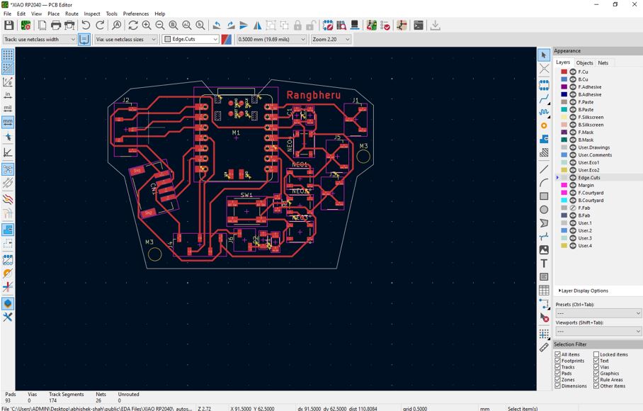
Final PCB Layout
Below image shows the final PCB layout. For 3D view, further, we can view it in to 3D viewer.
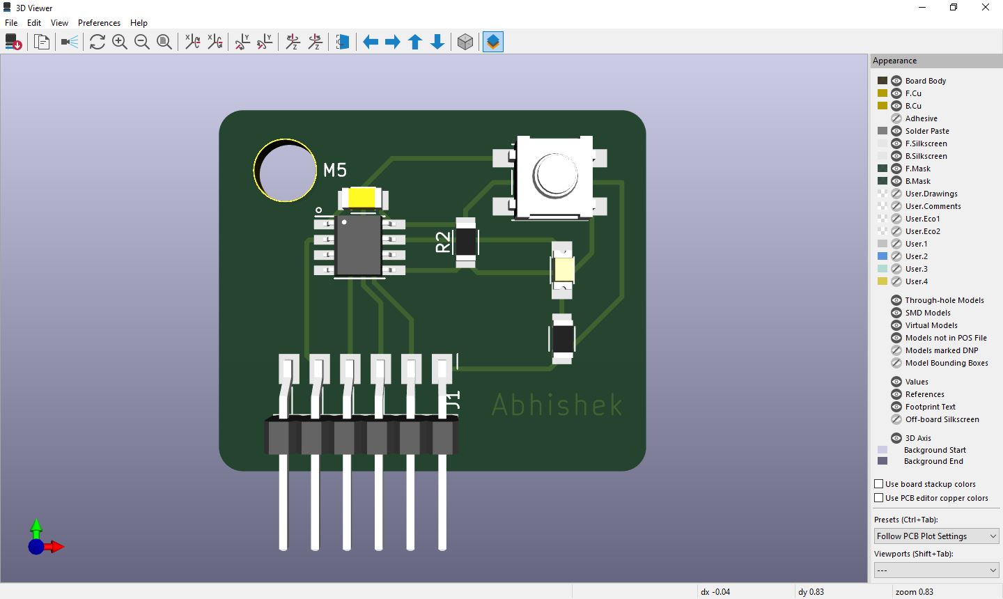
3D PCB Output
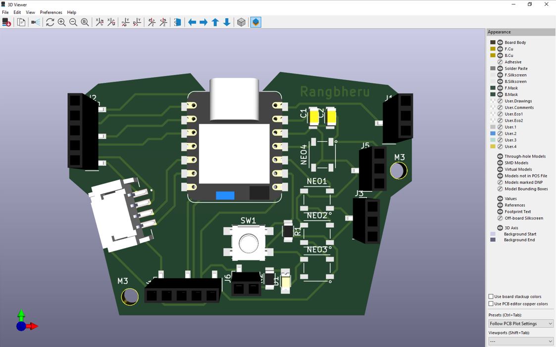
Now using 3D Viewer we can view 3D of the designed PCB.
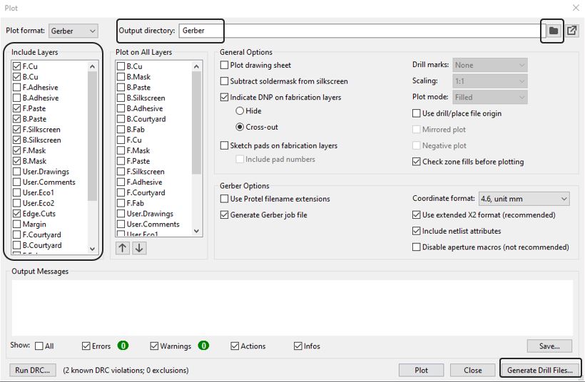
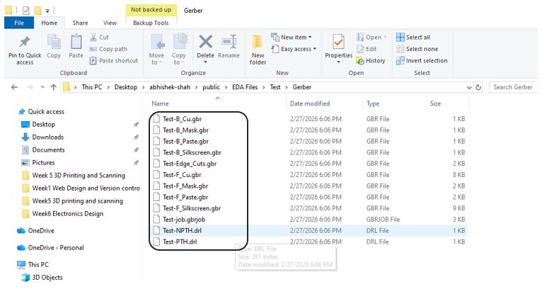
Gerber Export
To generate Gerber file go to File >> Fabrication Output >> Gerber (.gbr) >> Output directory >> Enter file "Gerber" >> Select the folder to save the files >> Generate Drill Files. This will generate Gerber (.gbr) file at the selected folder location in your PC.
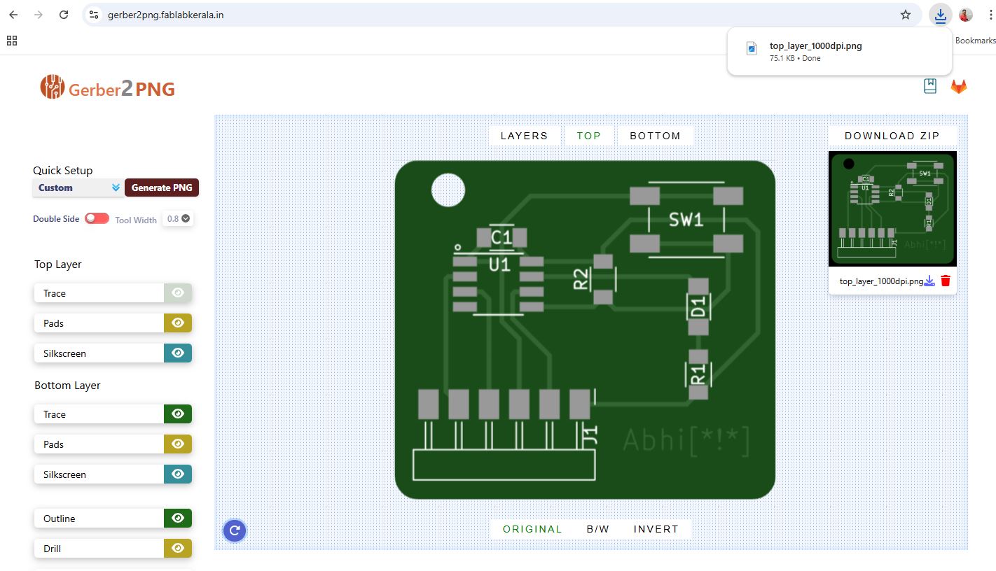
Using gerber2png.fablabkerala.in, we can generate image file from the gerber files. Click on Choose files >> Select all of the above gerber files >> Open >> Generate PNG. This will download a Image file of the designed PCB.
Alternatively, we can use the Gerber Viewer from the pcbway.com/project/OnlineGerberViewer.html. Upload your all the gerber and drill files.
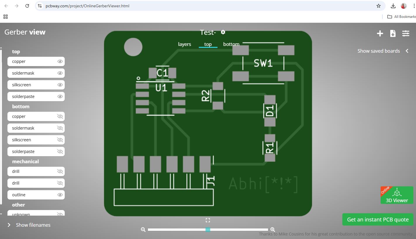
Lastly, we can check the Pricing and Build Time from the pcbway.com by upload your all the gerber and drill files, it automatically sets the board size, holes, track,, spacing for the files and shows the prizing for the given Material, Solder Mask color, Silkscreen color, Surface finish, etc.
Our instructor informed us to design a PCB using XIAO RP2040 that we can use during input and output week and also tinkering with out final project idea. He asked us to utilize all the pins that are available, specially connect I2C Header.
Adding External Component (Form snap EDA)
Below is step-by-step process to add external component to KiCad library.
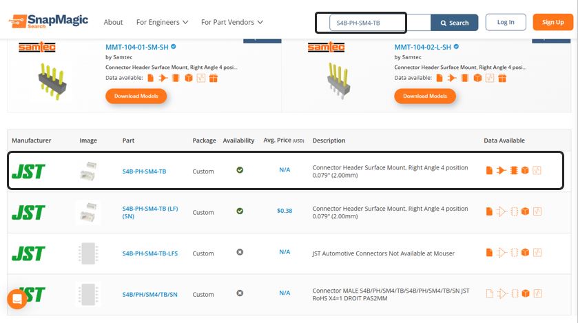
For I2C communication we need to use JST 4-pin 2mm pitch connector. which is not available on FAB Library. so our instructor taught how to download an external component and add to KiCad symbols. First step is to find and download the component CAD files. Open SnapMagic or similar CAD library site and search for the component using its exact part number (example: S4B-PH-SM4-TB).
So follow the steps - Search for the component using the part number >> Open the component page >> Click Download Symbol and Footprint >> Select KiCad as the format >> Download and extract the ZIP file.
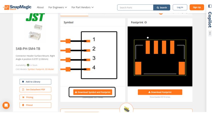
We will typically get below files.
- .kicad_sym → schematic symbol
- .pretty folder → footprint library
- .kicad_mod → footprint file
- .step → 3D model (optional)
The flow is adding is Symbol >> Footprint >> 3D Model (STEP)
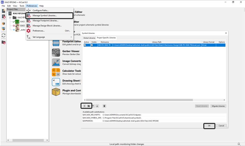
Adding symbol to KiCad Open KiCad main window >> Preferences >> Manage Symbol Libraries >> Project Specific Libraries >> Click + (Add Library) >> Browse and select the downloaded .kicad_sym file >> Click Open >> Click OK.
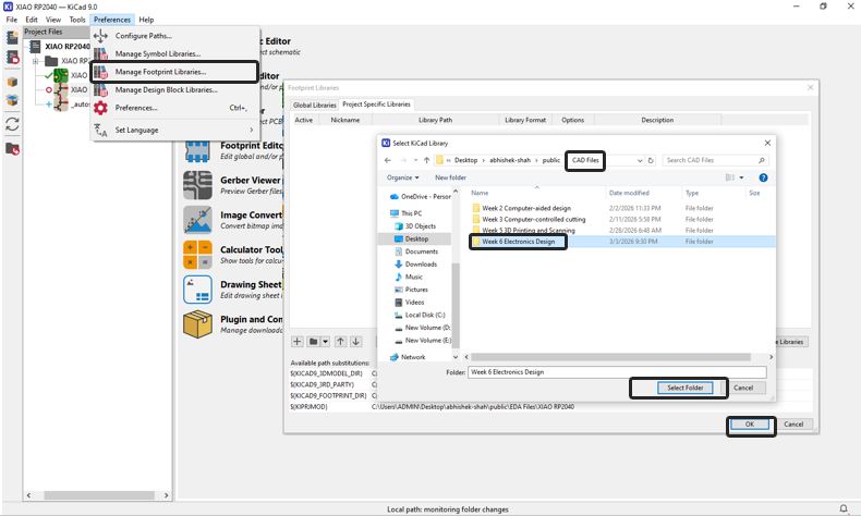
Adding the footprint to KiCad Open KiCad main window >> Preferences >> Manage Footprint Libraries >> Project Specific Libraries >> Click + (Add Library) >> Browse and select the downloaded .pretty folder (not the individual .kicad_mod) >> Click Open >> Click OK.
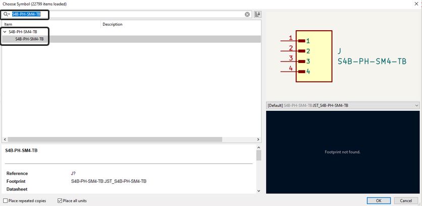
Use the symbol in schematic editor - Press A (Place Symbol) >> Search the component name >> Select it >> Click to place in schematic.
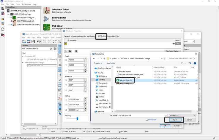
Adding a STEP File to a Symbol in KiCad In KiCad, a STEP file is not added to the symbol library. A STEP file is a 3D model, and it is attached to the footprint, not the symbol. The correct flow is adding is Symbol >> Footprint >> 3D Model (STEP). Open KiCad >> Go to Footprint Editor >> Open the footprint you want to modify (either from your project or a custom library).
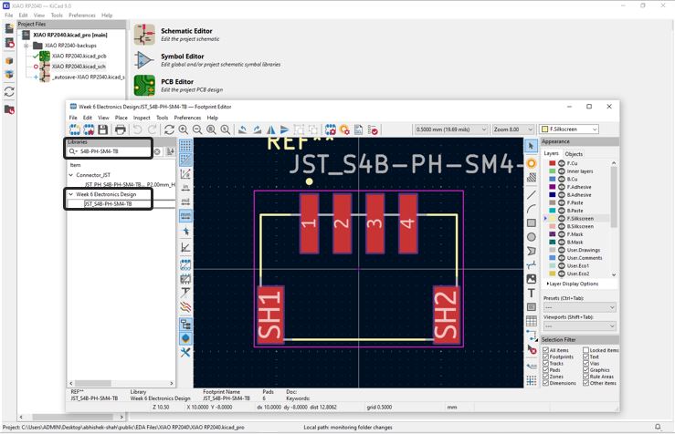
Open Footprint Properties and add th Step file, press E or Right-click >> Properties >> Footprint Properties >> 3D Models tab >> 3D Shape >> Browse the .step or .stp file >> Click OK
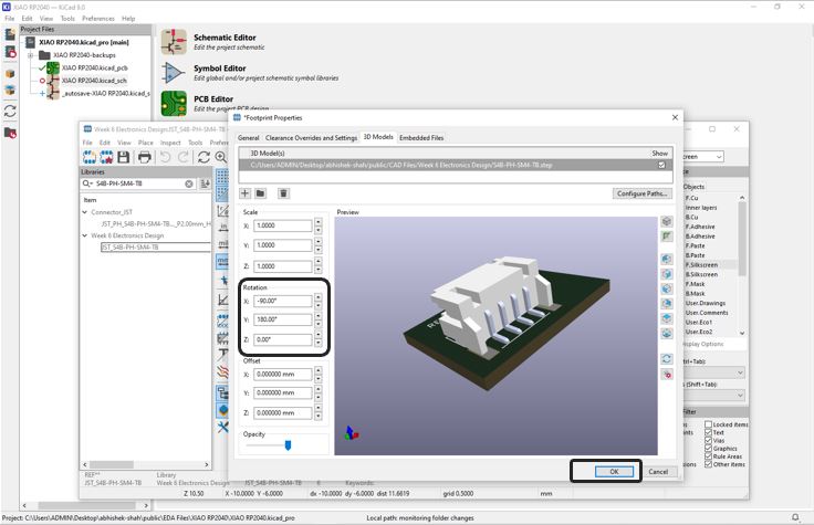
Adjust Model Alignment (Important) After adding:
- Use Rotation X/Y/Z if orientation is incorrect.
- Use Scale only if absolutely necessary (normally keep at 1.0).
- Use the 3D Viewer (Alt + 3) to check alignment.
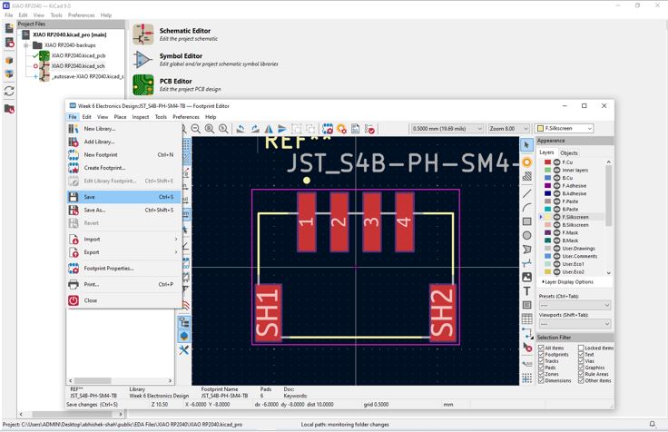
Save to Library - File → Save Footprint in Library, If modifying a default library footprint, save it into your own custom library instead.
Designing Custom XIAO Board
Our instructor informed us to design a PCB (under constrain of 75 mm X 50 MM size)using XIAO RP2040 that we can use during input and output week and also tinkering with out final project idea. He asked us to utilize all the pins that are available. Keeping this in mind I listed what all I need to tinker with my final project idea. I came up with the below list.
- XAIO but can be replicable between RP2040 and ESP32-S3
- I2C communication with 3.3V and also with 5V options
- A few 5V pins and a few 3.3V pins, with thicker tracks.
- A few GND pins with thicker tracks.
- TX-RX with 5V, 3.3V and GND.
- Digital IO Pins, Analog Pins
- Very important Power button and Bluetooth button
- Three NeoPixel LEDS
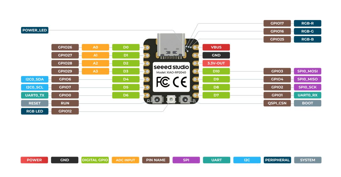
Pin out diagram of the XIAO
Below is the pinout details that I referred while designing in my custom XIAO board in KiCad. More details can be find here.
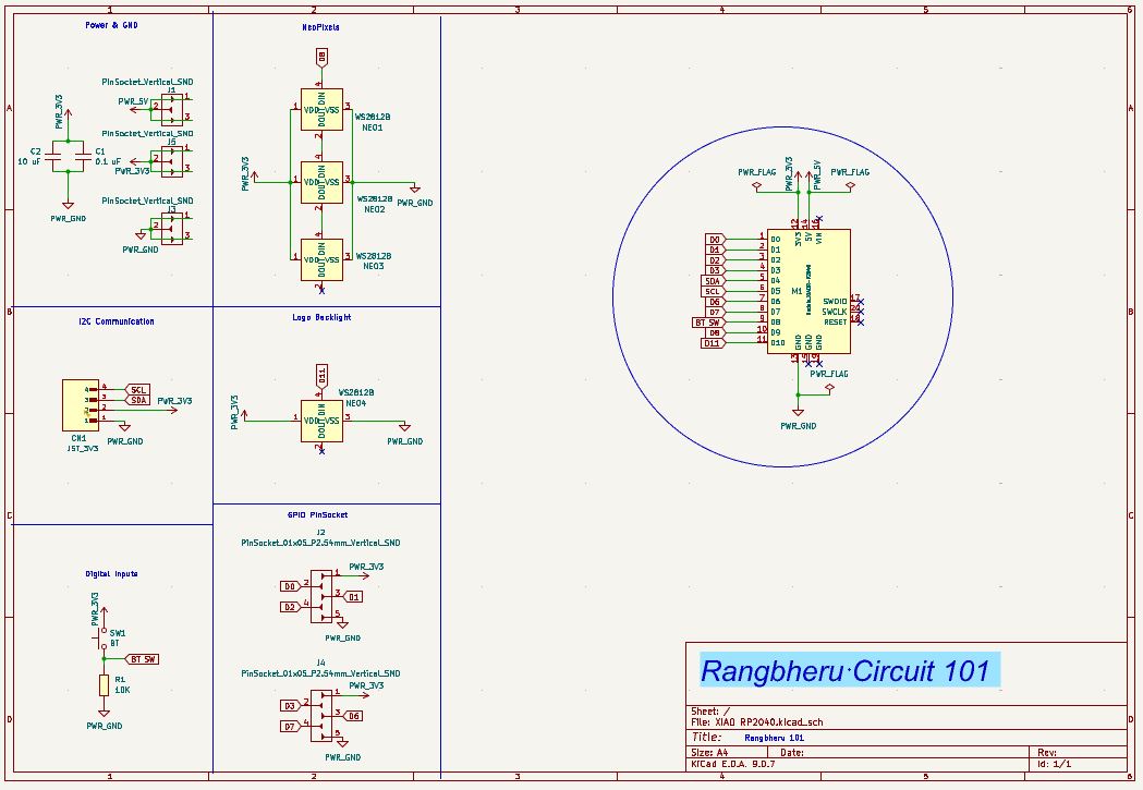
Final Schematic Diagram
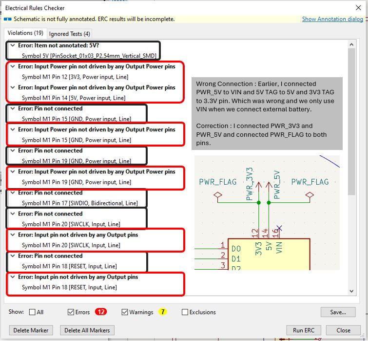
Electric Rule Check
I got below Errors while doing ERC for above schematics, I took my instructor's help and resolved it. I used multiple 5V, 3.3V and GND Tags, instead of which I shall use PWR_5V and PWR_3V3 directly at the places where power supply connection is required. and also added PWR_FLAG to all PWR_5V, PWR_3V3 and GND of controller pins.
Rangbheru PCB 101 Looks like Iron Man body suit.
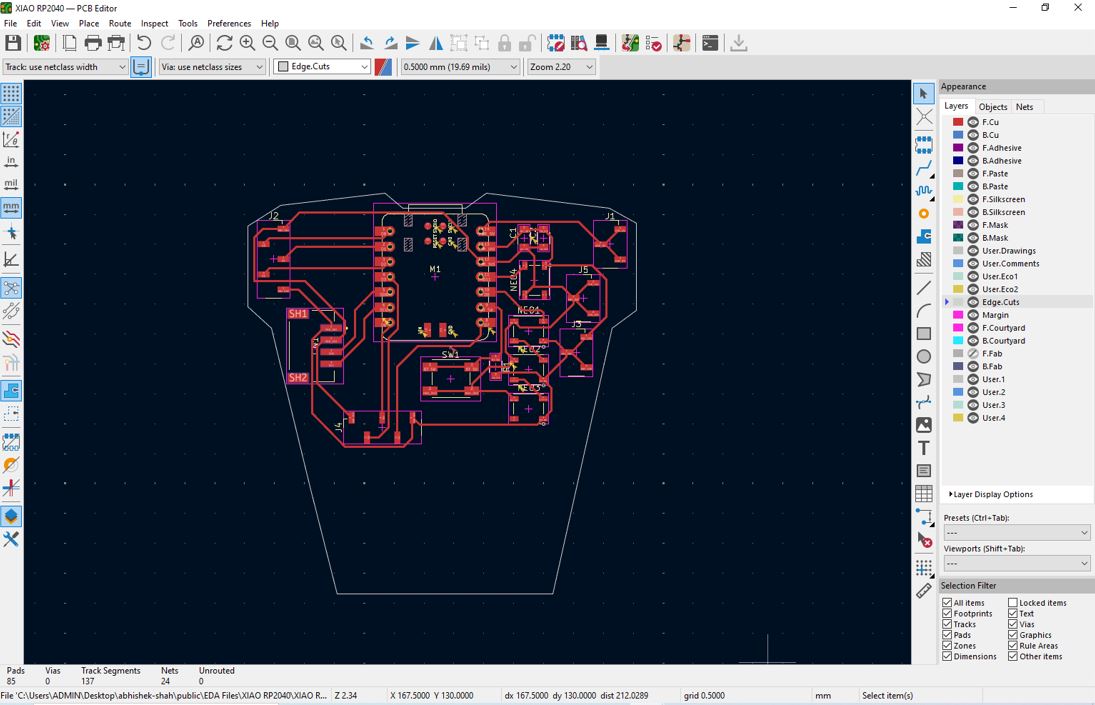
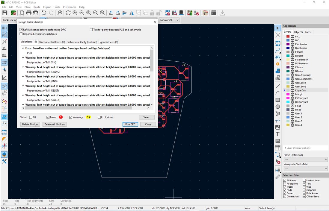
Design Rule Check
DRC Error appeared because I did not drew boundary. After adding the boundary I got Zero Errors
To use utilize the empty space at the bottom of the PCB cut the PCB and utilize it as a battery space and design an encloser for it.
3D Viewer
✨ Key Learnings This Week
- Decoupling Capacitor is connected between VCC and GND. It is placed near to VCC / IC Power pins. It is needed because Imagine your microcontroller as a tiny city that throws surprise parties every few nanoseconds. Each time it switches logic states, it suddenly gulps current. If the power supply is far away, the voltage line hiccups. That hiccup is noise. The transistors inside IC turn ON/OFF rapidly leading to sudden current spikes which further leads to power line voltage momentarily dip and noise spreads across PCB traces leading to IC random reset, errors, communication glitch, or malfunction. A capacitor stores charge >> when voltage drops >> it releases stored charge instantly >> when voltage rises >> it absorbs excess energy. For most microcontrollers typical value is 0.1 uF (100nF) ceramic capacitor, placed within a few millimeter of VCC. Some designers also use 10 uF or 1 uF electrolytic capacitors. The 0.1 uF is fast response and 10 uF is bigger energy reservoir.
- Avoid 90 ° bends instead provide Two 45° bends in the PCB design because 90 ° bends causes Current Crowding - A right angle becomes a tiny speed bump, secondly act like tiny antennas in high speed circuits and increase electromagnetic emissions.
Design Files Download Links
- PCB Design Files for ATtiny412 Board kicad_pro, kicad_sch, and kicad_pcb
- PCB Design Files for XIAO Board kicad_pro, kicad_sch, and kicad_pcb
Useful Links
- KiCad Software Download Link
- KiCad FabLib Installation Guide