🧩 Week 5 – 3D Printing and 3D Scanning
📚 Assignment Overview
- Group assignment:
- Test the design rules for your 3D printer
- Individual assignment:
- Design, document, and 3D print an object that could not be made subtractively (small, few cm3, limited by printer time)
- 3D scan an object (and optionally print it)
This week’s assignment focused on designing and 3D printing a small object (limited to a few cubic centimeters) that cannot be manufactured using subtractive methods. In addition, we were required to perform 3D scanning of an object, with the option to 3D print the scanned model.
The objective was not just to print something, but to understand:
- How additive manufacturing works
- The limitations of our 3D printer
- Design rules for print-in-place mechanisms
- Basics of professional 3D scanning
The main learning was understanding that design for additive manufacturing is very different from conventional machining.
🔷 Group Assignment – Exploring 3D Printing
During the group assignment, we explored different types of 3D printing technologies and compared their advantages and disadvantages. We also studied printer workflow before starting any print.
Key areas covered:
- Types of 3D printing (FDM, SLA, etc.)
- Advantages and limitations of additive manufacturing
- Safety procedures before and during printing
- Design rules for additive manufacturing
- Types of materials used in 3D printing
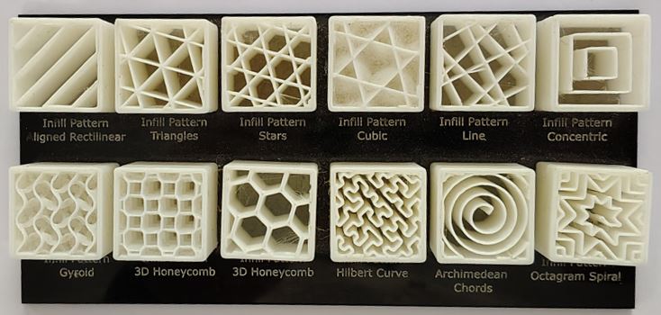
- Different infill patterns and their applications
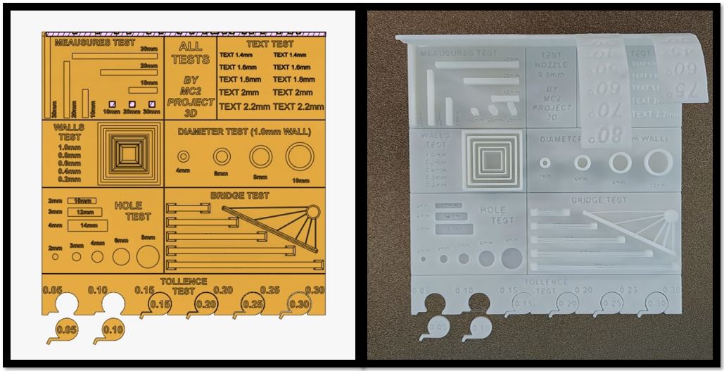
- Tolerance testing and overhang testing
Since we are using the Bambu Lab A1, we explored:
- Different build plates
- Printer capabilities
- Slicer settings in Bambu Studio
For more details, please visit our group assignment page.
Link: Week 5 Group Assignment
🔷 Introduction to 3D Printing
3D printing, also known as additive manufacturing, is a process of creating three-dimensional objects by depositing material layer by layer from a digital model.
Unlike traditional manufacturing methods that remove material (cutting, drilling, milling), additive manufacturing builds objects progressively. This allows:
- Complex internal geometries
- Reduced material waste
- Print-in-place assemblies
- Faster prototyping
Complex internal parts that are impossible to machine can be produced in a single print.
3D printing is widely used in prototyping, automotive development, medical applications, architecture, and product design.
Filament Material Overview - PLA, PLA+, PAG & PAG-HS
PLA (Polylactic Acid)
PLA most common beginner-friendly filament. Easy to print, low warping, good surface finish, but relatively brittle and not suitable for high temperatures or mechanical loads.
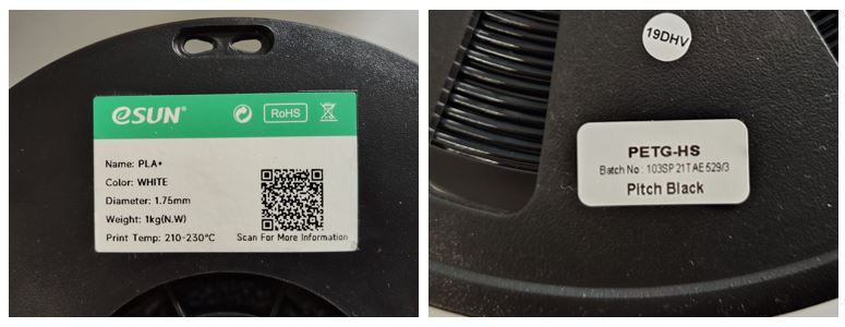
Sample example: eSUN PLA
eSUN PLA+ is a modified PLA that enhances toughness, impact resistance, and layer adhesion compared to basic PLA. It prints easily at ~210–230 °C and is suitable for functional parts. PLA+ has good balance of strength and surface quality.
The Datasheet has information about Physical, Mechanical, Thermal, and Electrical properties Typical value tested by standard testing methods such as GB/T, IEC and DIN.
Datasheet Specifies - Recommended printing parameters
| Extrude Temperature | 210-230 °C |
| Build Platform Temperature | 45-60 °C |
| Build Platform Temperature | 45-60 °C |
| Fan Speed | 100 % |
| Printing Speed | 40 - 100 mm/s |
eSUN PLA-HS is engineered for high-speed printing with better melt fluidity and retained mechanical performance even at fast speeds. It offers a slightly higher toughness and still prints in a similar temperature range.
Standard PAG (Polyamide / Nylon-based)
A strong engineering-grade material known for flexibility, impact resistance, and durability. It absorbs moisture and requires higher printing temperatures. Suitable for functional mechanical parts.
Sample example: Numakers PETG-HS
PAG High-Speed Nylon variants (e.g., high-flow nylon) tend to offer improved melt flow for faster printing, similar or slightly higher strength to standard Nylon, reduced impact from fast deposition.
- Diameter : 1.75 mm
- Nozzle Temp : 220-250 °C
- Bed Temp : 70 -90 °C
| Property | PLA | PLA+ | Standard PAG | PAG-HS |
|---|---|---|---|---|
| Print Difficulty | Very Easy | Easy | Moderate to Difficult | Moderate |
| Strength | Medium | Medium to High | High | Very High |
| Impact Resistance | Low (Brittle) | Moderate | High | Very High |
| Flexibility | Low | Low to Moderate | High | High |
| Heat Resistance | Low (~60°C) | Slightly Higher | High | High |
| Warping Tendency | Very Low | Low | High | Medium |
| Moisture Sensitivity | Low | Low | High (Needs Dry Storage) | High |
| Best Use Case | Prototypes, models | Stronger prototypes | Functional mechanical parts | High-performance parts |
AI Prompt: help me to compare PLA, PLA+, Standard PAG and PAG-HS? please make the comparison simple to understand and also give table for comparison.
🔷 About the Printer – Bambu Lab A1
Bambu Lab A1 is a high-speed, user-friendly desktop 3D printer with a build volume of 256 × 256 × 256 mm. It supports print speeds up to 500 mm/s and includes advanced calibration features.
Key Features:
- Automatic bed leveling
- Dynamic flow calibration
- Vibration compensation
- Quick-swap nozzle system
- Multi-color printing (with AMS Lite)
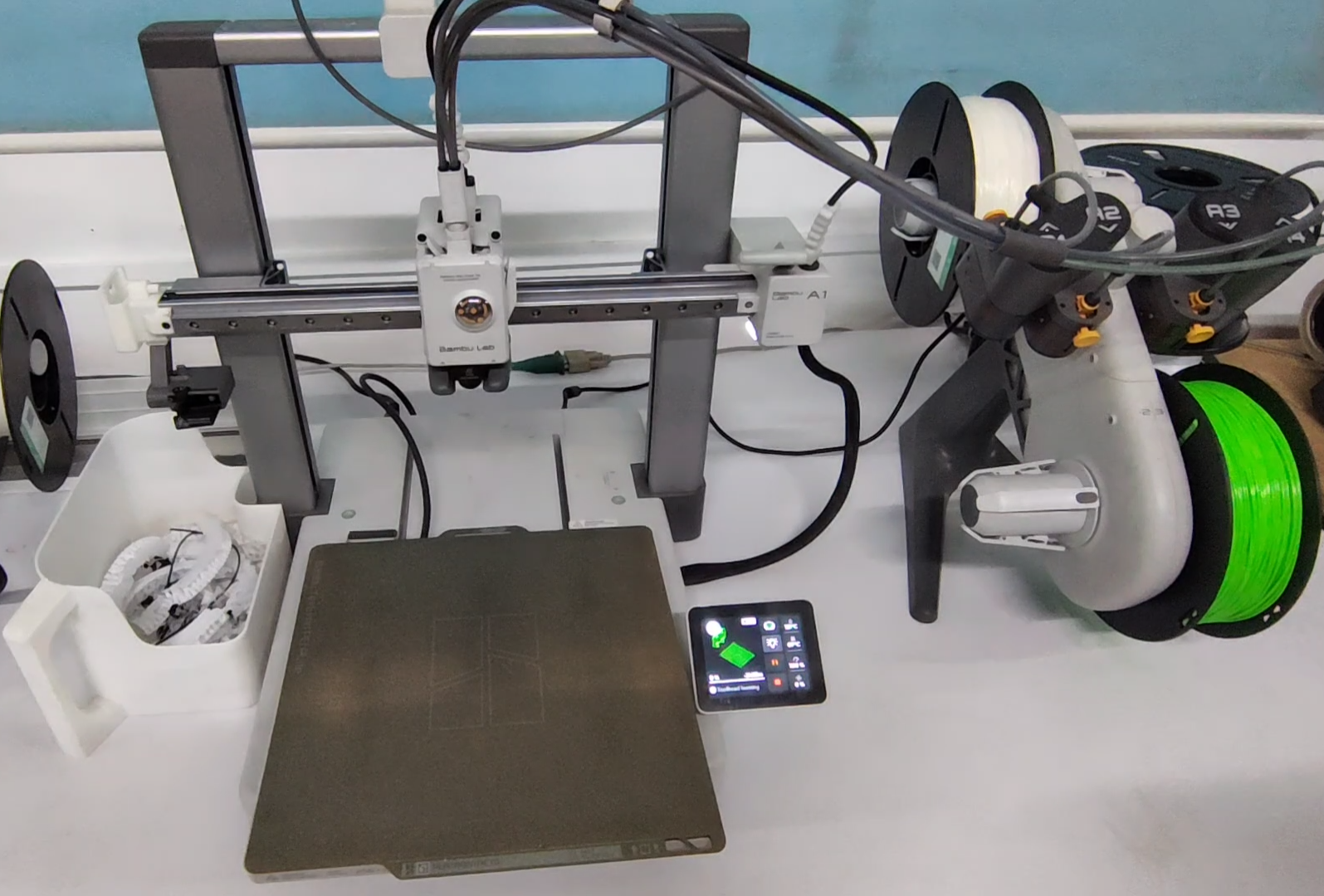
One feature I particularly liked was the fully automated pre-print calibration sequence.
Before printing starts, the printer performs:
- Toolhead homing
- Heating sequence
- Push New Filament
- Purge Old Filament
- Dynamic flow calibration
- Vibration compensation
- Toolhead cleaning
- Bed leveling
This automation significantly reduces manual errors and improves print reliability.
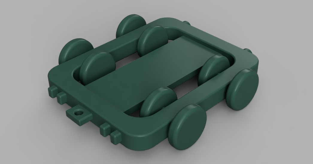
🔷 Individual Assignment – Print-in-Place Car Chassis
We were required to design a small object (5 cm × 5 cm × 5 cm). Due to my automotive background, I designed a 5 cm × 4 cm miniature car chassis with integrated rotating wheels.
The idea was to create a print-in-place assembly where:
- Wheels rotate freely
- Axle is integrated into the chassis
- No post-assembly is required
This geometry cannot be manufactured using subtractive methods because the shafts are enclosed inside the chassis.
Making 3D design I used Fusion 360 to make the tiny car chassis design, first I made two rectangles using sketch tool then used fillet tool to round the corners. After this I used extrude tool to extrude the chassis. Now major things is to make the wheels shaft and hole in chassis and give offset. Create two construction plane normal and centred to chassis along its width and length using offset plane tool. Now make one hole to the chassis using hole tool then use mirror tool to mirror the hole across two mirror plans that we created in earlier step. How using sketch and extrude tools I made wheels and shaft, here make sure that you give 0.25mm radial clearance. Or define offset as parametric value so that we can change it depending on 3D printer limits. Then again I used mirror tool to mirror wheel to create remaining 3 wheels across mirror plans that I created.
Designed using: Autodesk Fusion
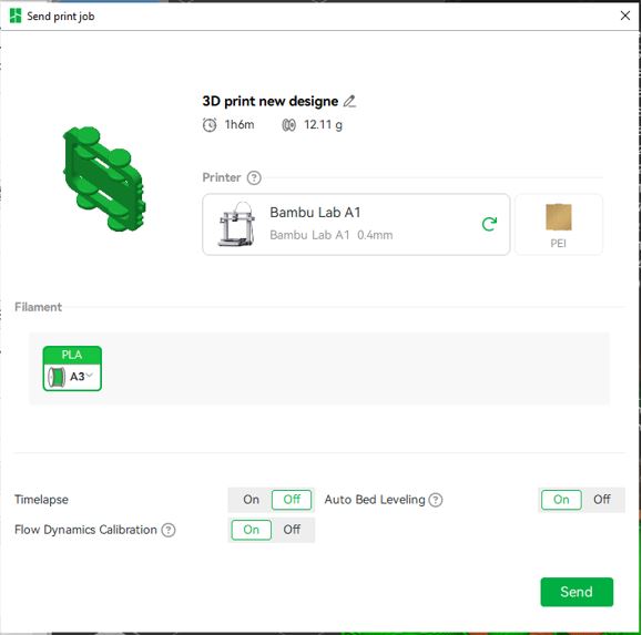
Slicer Software
I used Bambu Studio as slicing software developed by Bambu Lab that is used to prepare 3D models for printing. It converts a 3D model into machine instructions (G-code) that the printer can follow to create the object layer by layer. It is an open-source software and it allows to import 3D files such as STL, OBJ, STEP, and 3MF.
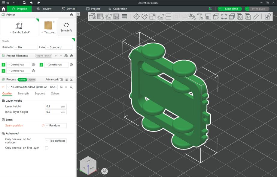
First, export the file as .STL from Fusion 360 and then open the .STL file in Bambu Studio software and configer the following parameters.
- Printer: Bambu Lab A1
- Plate type: Textured PEI Plate
- Nozzle diameter: 0.4 mm
- Filament: Generic PLA
- Process: 0.20 mm Standard @ BBL A1
Quality Settings
- layer Height: 0.2 mm
- Initial layer height: 0.2 mm
- Seam position: Random
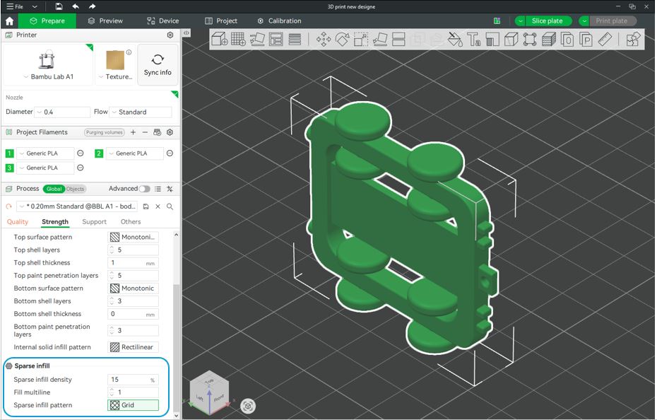
A few, important and useful settings are as below:
- Strength --> Sparse infill : Grid
- Support --> Type : tree(Auto)
- Others --> Brim type : Outer Brim (for more flat designs to avoid failure)
After clicking Slice Plate, I reviewed the slicing result under Line Type (Color Scheme). The preview showed:
- Inner wall (yellow)
- Outer wall (orange)
- Top Surface (Red)
- Bottom Surface (Purple)
- Sparse infill (Maroon)
- Internal solid infill (Purple)
- Gap fill (white)
- Seams
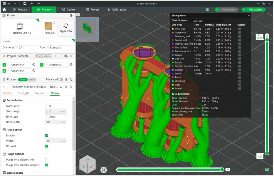
If everything looks ok then we can click on the Print plate button on the top right corner. Then, select the filament color and click Send.
🔷 Critical Design Parameter – Clearance
The most important factor was the clearance between:
- Outer diameter of shaft
- Inner diameter of chassis hole
Clearance = Dhole − Dshaft
- Clearance ≈ 0 → parts fuse
- Clearance too small → friction lock
- Clearance adequate → smooth rotation
- 0.2 mm → usually fused
- 0.3 mm → tight
- 0.4–0.5 mm → safer for rotation
🔷 What Went Wrong
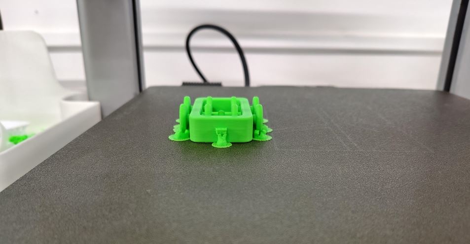
❌ Problem 1 – Wheel Broke During Support Removal
- Two wheel fractured
- The wheel–shaft interface is fragile due to the print orientation (anisotropy).
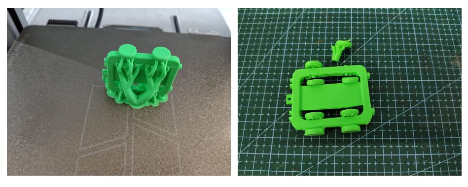
❌ Problem 2 – Wheels Did Not Rotate
The remaining wheels were fused and unable to rotate.
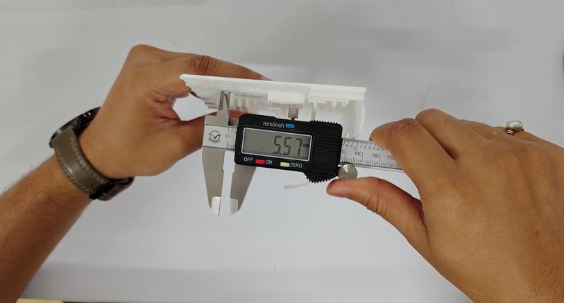
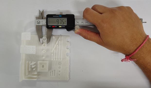
Root Cause Analysis:
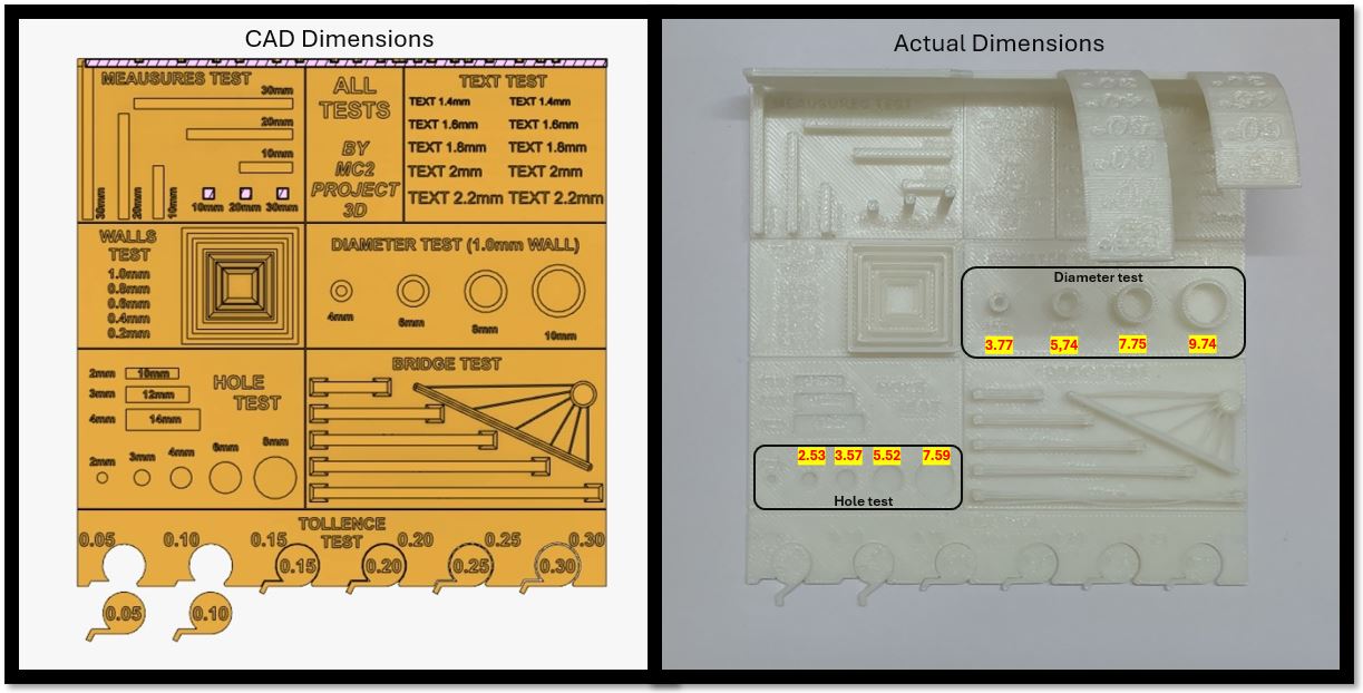
- Not the Insufficient Clearance but neglecting printer error
- Average Hole Test Error = −0.45 mm and Diameter Test Error = −0.25 mm
- Clearance = 0.25, Chassis Dia = 3 mm, Shaft Dia = 2.75 mm [Clearance = Chassis Dia - Shaft Dia]
- Print-in-place design requires higher tolerance margin
- Slight over-extrusion / overhang
- Extrude length was 2 mm, shall be less then 1mm
- The head lamps and tail lamps : 90° shall be 45° (depending upon print orientation)
CAD dimensions were correct, but real-world printing tolerances caused failure.
This was a practical lesson in tolerance stack-up and real-world manufacturing variation.
Second Print Outcome (Improved Design & Print Strategy)
After the failure of my first 3D print, I carefully analyzed the issues related to tolerances, overhangs, and print orientation. In the second iteration, I redesigned the model by adjusting dimensions and improving print strategy to enhance both functionality and print quality. I reduced the chassis hole size and adjusted the shaft diameter while maintaining 0.25 mm radial clearance to ensure smooth wheel rotation. I also minimized unsupported geometries by redesigning overhangs to follow a 45° angle, which reduced the need for supports. Additionally, I introduced a small top surface offset and printed the chassis upside down, significantly decreasing support material usage and improving surface finish. The final print was clean, structurally stable, and functionally successful, as verified through a rolling test on a laptop keyboard.
- 0.25 mm radial clearance between shaft and chassis hole
- Optimized 45° overhang design to reduce supports
- Improved print orientation (upside down) strategy
- Reduced support usage and improved surface finish
- Successful rolling and functional validation
🔷 3D Scanning – Introduction to Artec Leo
We were introduced to the professional 3D scanner: Artec Leo
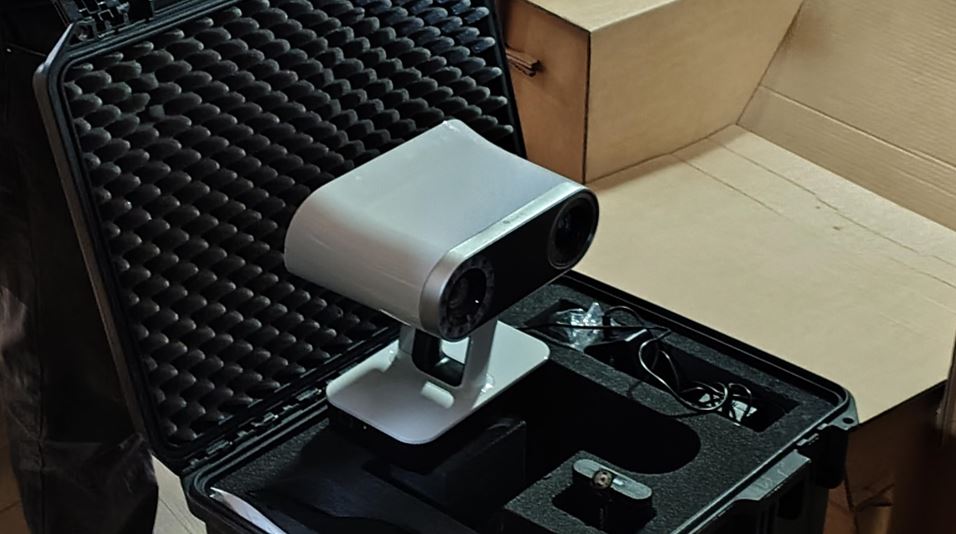
The Artec Leo is a wireless, handheld 3D scanner with real-time visualization on a built-in screen. It processes data onboard without requiring external computers during scanning.
Key Features:
- Real-time 3D reconstruction
- High frame rate scanning
- Wireless operation
- Built-in touch display
- 9 DoF inertial system
Scanned data is processed using: Artec Studio
- Automatic alignment
- Erase unwanted scans
- Base removal
- Noise removal
- Mesh refinement
- Hole Filling
- Exporting STL files
📡 3D Scanning – Wooden Bicycle using Artec Leo
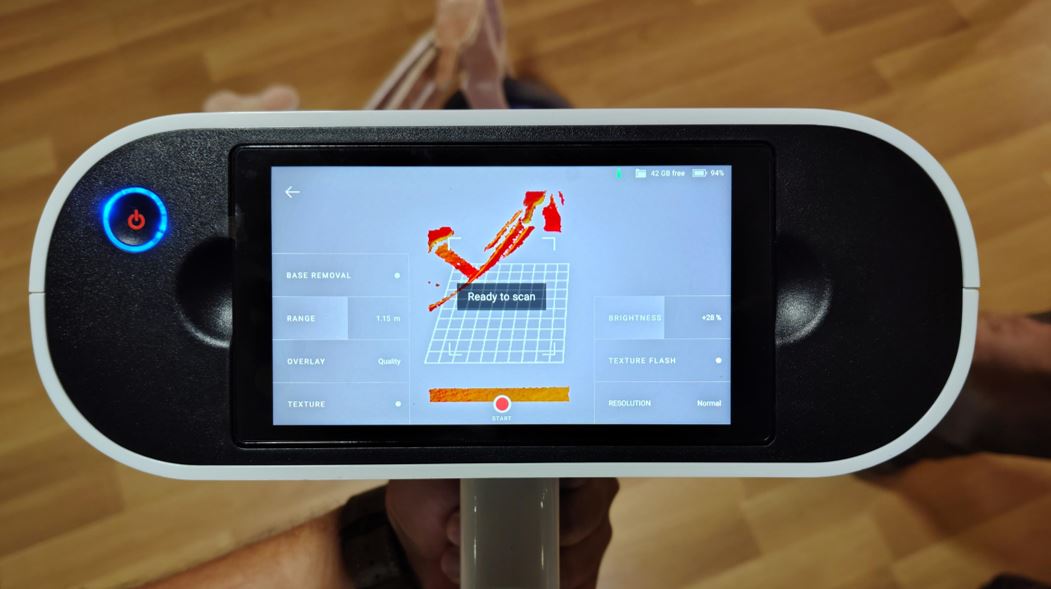
For the 3D scanning assignment, I selected a downscaled wooden bicycle model. I scanned the object using the Artec Leo handheld 3D scanner. This is very high quality 3D scanning equipment more widely used for scanning large scale objects such as excavation sites, heritage buildings, artifacts usually to preserve their designs. I placed the bicycle on the floor then selected the first option on the Artec screen to select the base plane in Base Removal, I selected the floor so the scanned does not scan below the hight of the floor. Then set the Range and Brightness it will show Ready to scan then stated the scanning by clicking on Start Button on the screen. Slowly moved the scanner around the object make sure that all the Red surface area on the bicycle are captured and appear Green/Yellow.
Initially, I placed the bicycle directly on the floor for scanning. Later during post-processing, I realized that placing it on a table would have improved the scan quality, especially for capturing the underside geometry, which was difficult to acquire when the object was on the ground.
However, keeping the bicycle on the floor also had an advantage. I was able to define the floor as the scanning base, which allowed the scanner to use it as a reference surface and exclude unnecessary floor data.
- Object: Wooden miniature bicycle
- Scanner Used: Artec Leo
🖥 Post-Processing Workflow in Artec Studio
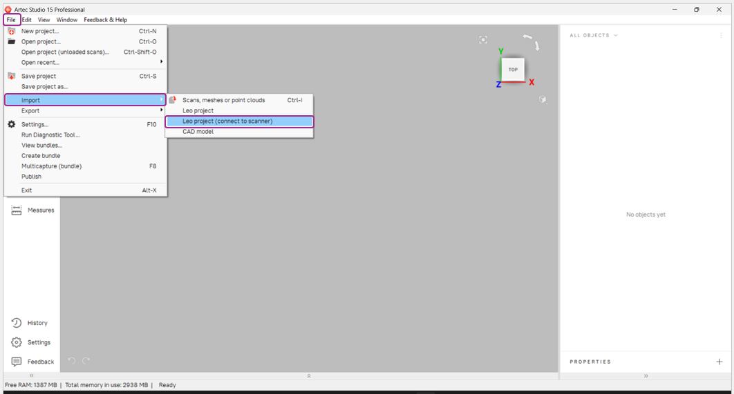
After completing the scans, I transferred the data to Artec Studio for processing. The scanner was connected to the computer using an Ethernet cable, and the scanned files were imported via: File → Import.
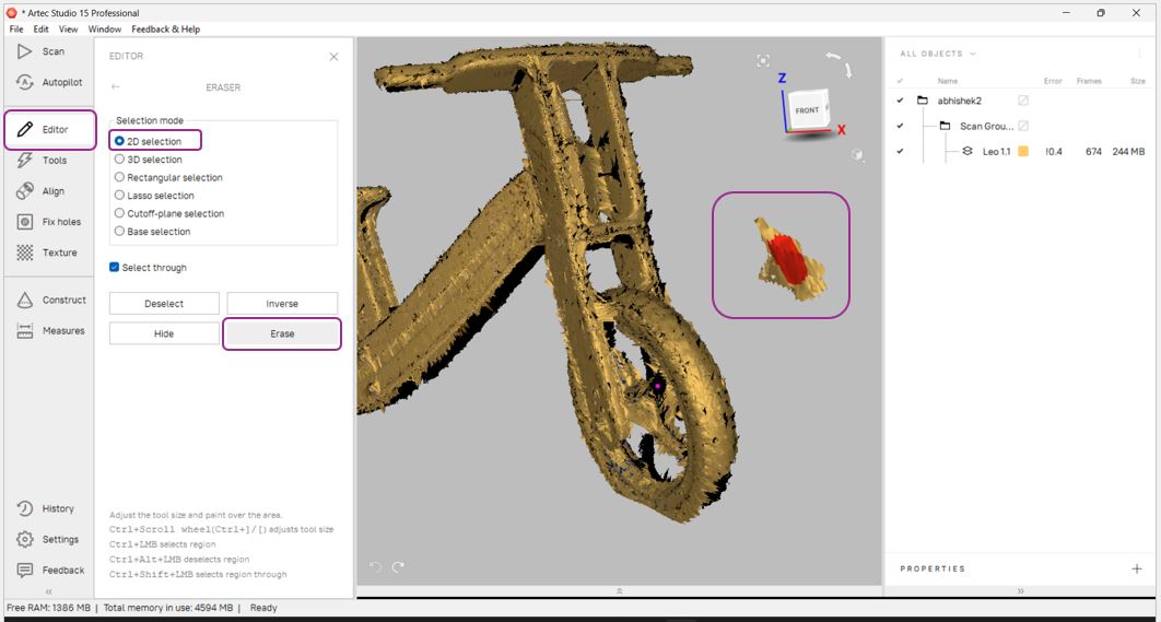
The first step in processing was to remove unwanted surrounding elements. Using the Editor tab, I selected unnecessary objects and erased them.
- Editor → 2D Selection → Erase
- Alternative tools: 3D Selection, Rectangular Selection, Lasso Selection
- Base Selection used to remove data below a defined surface
🔄 Alignment and Outlier Removal
Since the object was scanned in multiple passes, it resulted in multiple scan layers. These layers were aligned using the Auto Align function.
- Align → Select All Layers → Auto Align
After alignment, the next step was to improve geometric accuracy using:
- Global Registration (Tools → Global Registration → Apply)
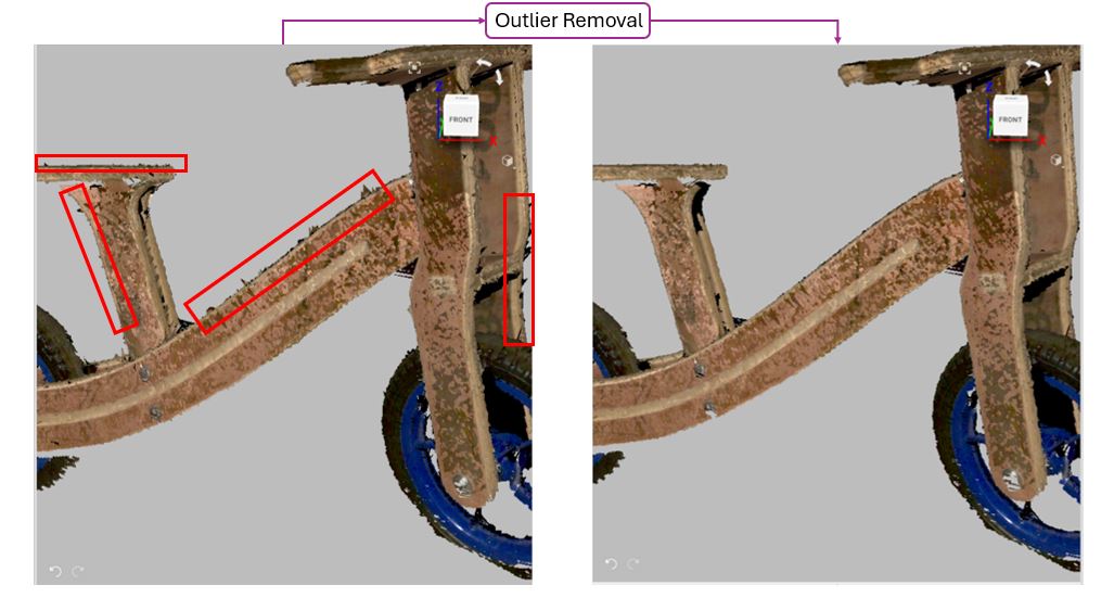
- Outlier Removal to remove noise and sharp artifacts
- Smooth Fusion to generate a continuous surface
The Outlier Removal tool was especially useful for eliminating scattered data points and smoothing rough edges.
🧩 Mesh Optimization
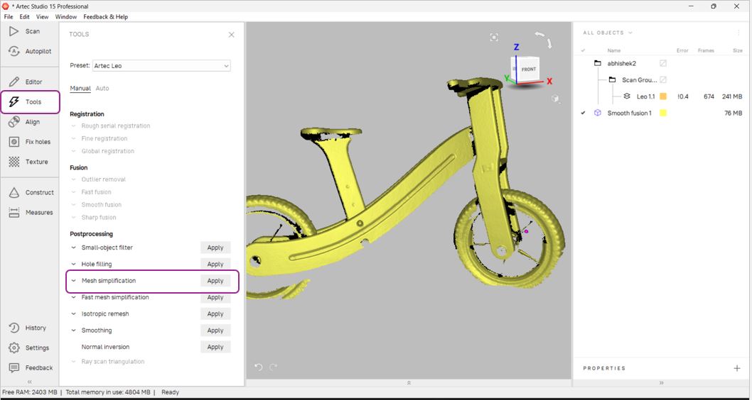
After fusion, I used the Mesh Simplification tool to reduce polygon count and optimize the model for easier handling.
- Tools → Mesh Simplification
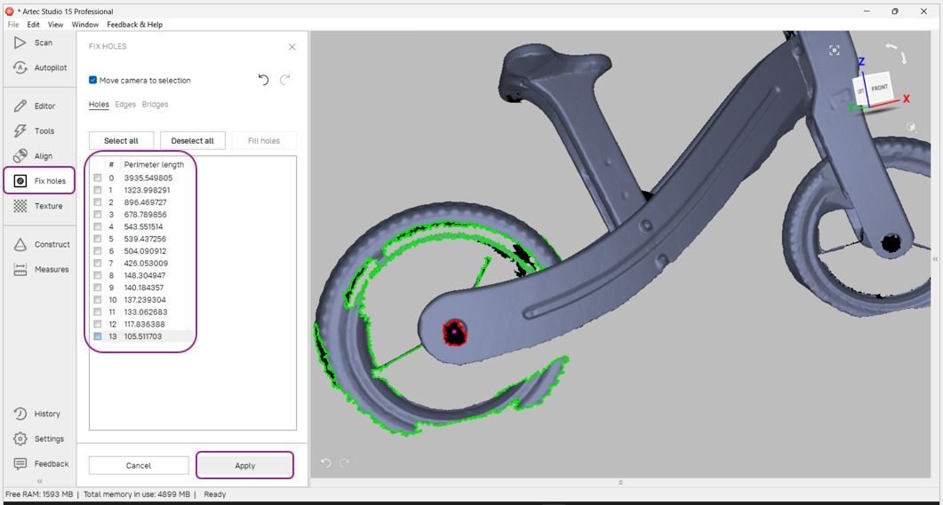
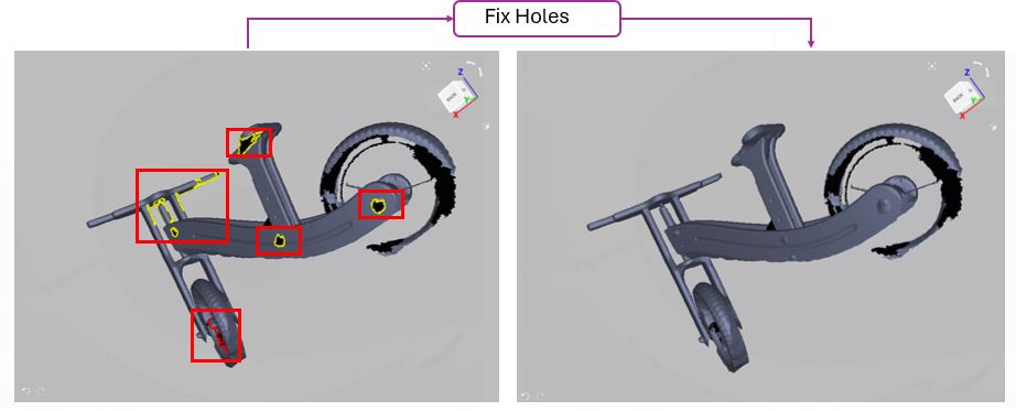
Hole Fixing
During inspection, I observed several holes and missing surfaces where the scanner could not capture data properly. These were repaired using the Fix Holes function.
However, some filled regions, especially on curved surfaces, appeared slightly dented or less smooth due to limited original scan data.
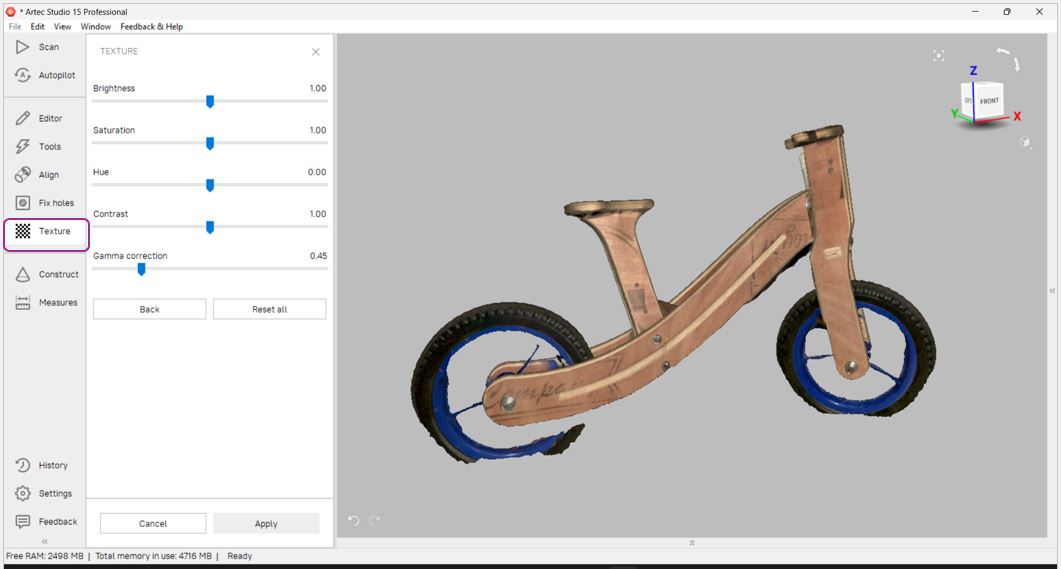
🎨 Texture Application and Export
In the final stage, I applied the texture to the processed mesh to preserve the visual details of the wooden surface.
- Texture → Select All Scans → Apply
- Save the project file
- Export the model as STL via File → Export
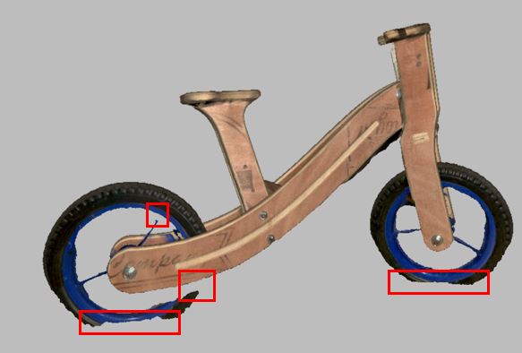
The final output was a cleaned, aligned, fused, however it needed a few correction before 3D printing. Some filled regions, especially on curved surfaces, appeared slightly dented or less smooth due to limited original scan data.
🔷 Key Learnings This Week
- Print-in-place mechanisms require tolerances which changes printer to printer thus defining offsets as parametric value is very important
- Tolerances, x - directional shrink, y - directional shrink and z - directional shrink can be define as parametric
- Try to design such that no or minimum support is needed
- Vertical placed print takes longer time then horizontal prints (more hight more time due to retractions)
This week helped bridge the gap between digital design and physical reality.