Week 2. Computer-aided design
This week focused on modeling a potential final project using 2D and 3D design tools (raster, vector, 2D, 3D, rendering, animation, and simulation). We installed and were introduced to Fusion 360, Inkscape, Photopea, Affinity, and Blender. We also learned how to optimize and compress images and videos, and finally documented the work by posting design files with descriptions.
2D Design
Raster images Vs. Vector images
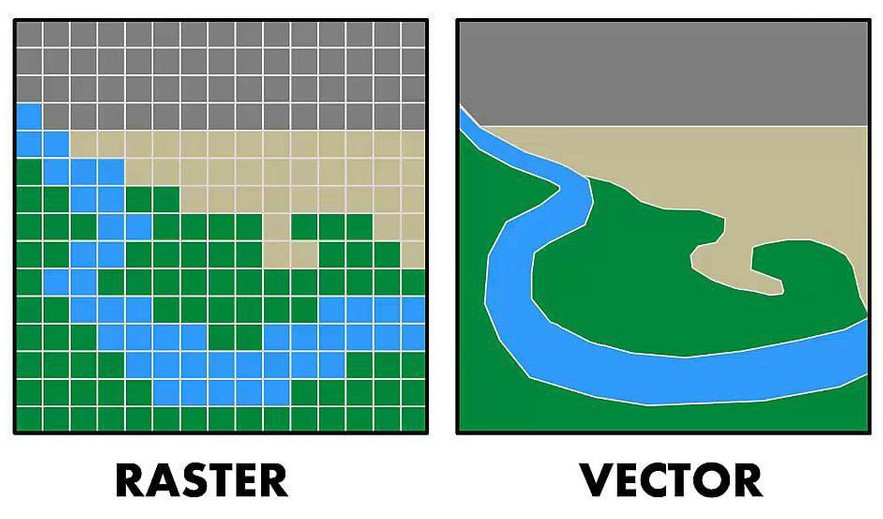
A raster image is made up of pixels (tiny squares of color). Each pixel has a fixed position and color. Raster images are resolution dependent thus it looses quality when zoomed in. Raster image formate is use for photographs and detailed images which has more colors and shades for example photo taken by camera or phone, screenshots, edited images in Photoshop or Photopea. Raster images are great for documentation, photos of projects and textures, but not ideal for laser cutting or CNC. Common raster formats are JPEG / JPG, PNG, GIF, BMP, TIFF etc.
A vector image is made using mathematical paths (lines, curves, shapes) instead of pixels. Therefore Vector images are resolution-independent (can be zoomed infinitely), they are perfectly shaped, and file size is usually small. Vector image formate is use for fabrication for example, laser cutting files, vinyl cutting, CNC milling, PCB outlines, CAD sketches, Logos etc. Vector image formats are SVG, DXF, AI, EPS, and PDF (vector-based).
| Feature | Raster | Vector |
|---|---|---|
| Made of | Pixels | Mathematical paths |
| Zoom without loss | ❌ No | ✅ Yes |
| Fab Lab use | Documentation | Manufacturing |
| Best for | Photos & screenshots | logos, posters and fabrication |
| Formats | JPEG, PNG, GIF, BMP, TIFF | SVG, DXF, AI, EPS, PDF(vector based) |
Inkscape
In simple terms, Inkscape is used to draw clean, scalable designs made of lines and curves instead of pixels.
Inkscape is use to create vector drawings and illustrations, to design logos and icons, to prepare files for laser cutting, vinyl cutting, and CNC, to convert raster images (PNG/JPG) into vector paths (SVG).
It works with SVG (Scalable Vector Graphics) format,Supports layers, paths, nodes, and text tools, the files can be scaled infinitely without losing quality, it is free and runs on Windows, macOS, and Linux
Inkscape is commonly used for designing laser-cut parts, creating vinyl-cut graphics, preparing 2D fabrication files, and editing SVG files before sending them to machines
Inkscape is not for photo editing (use Photopea), not for 3D modeling (use Fusion 360 or Blander), not for mechanical constrains or assemblies.
Inkscape native format is SVG, we can export in PDF, DXF, PNG.
I was not very familiar with Inkscape, so it took some time to understand where the tools were located and how they functioned. I started by creating simple shapes and experimenting with the shape tools. As part of this exploration, I decided to design a logo for my computational wearable textile project.
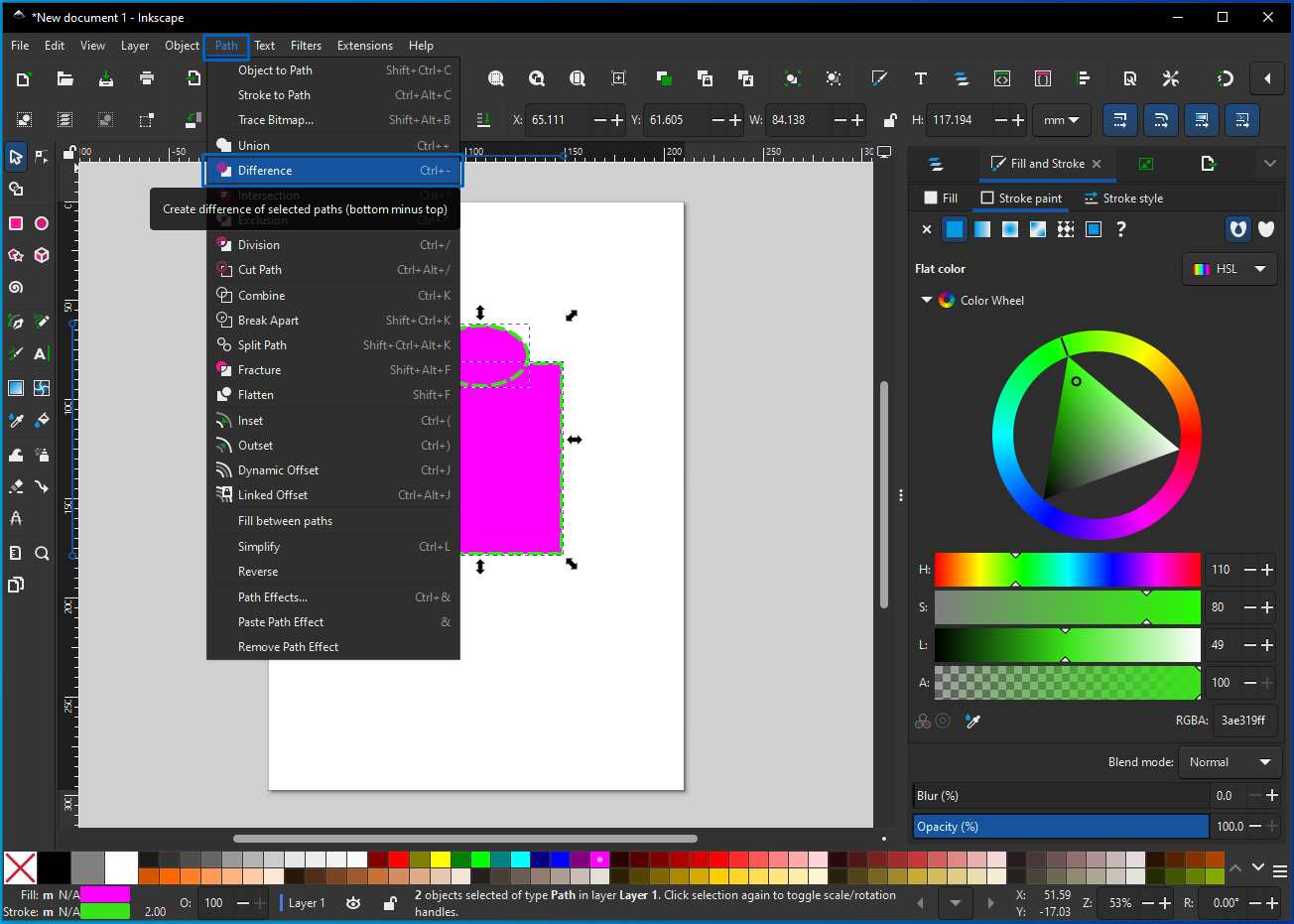
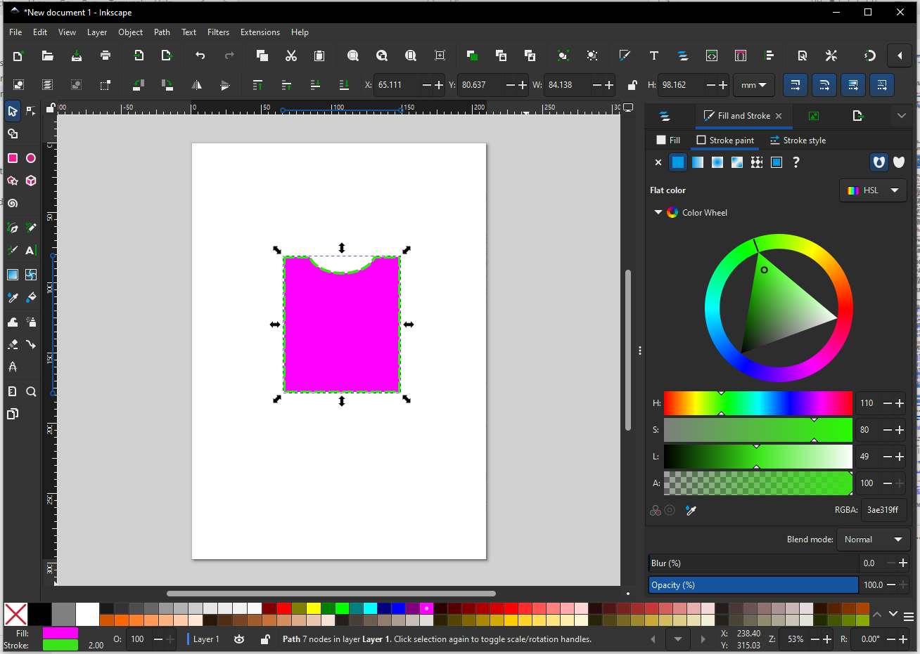
I learn to perform Boolean operation, first press shift and select two objects between which we need to perform operation then under path tab I selected difference.
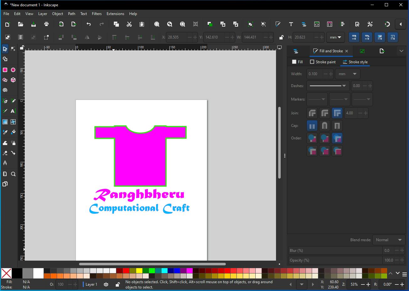
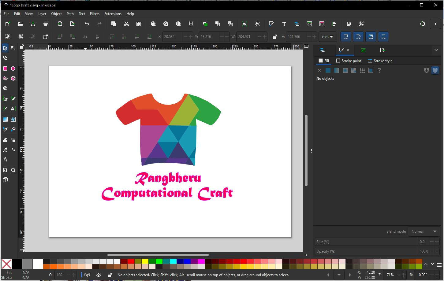
I then used the text box tool to write some text to finish off the Draft design of logo.
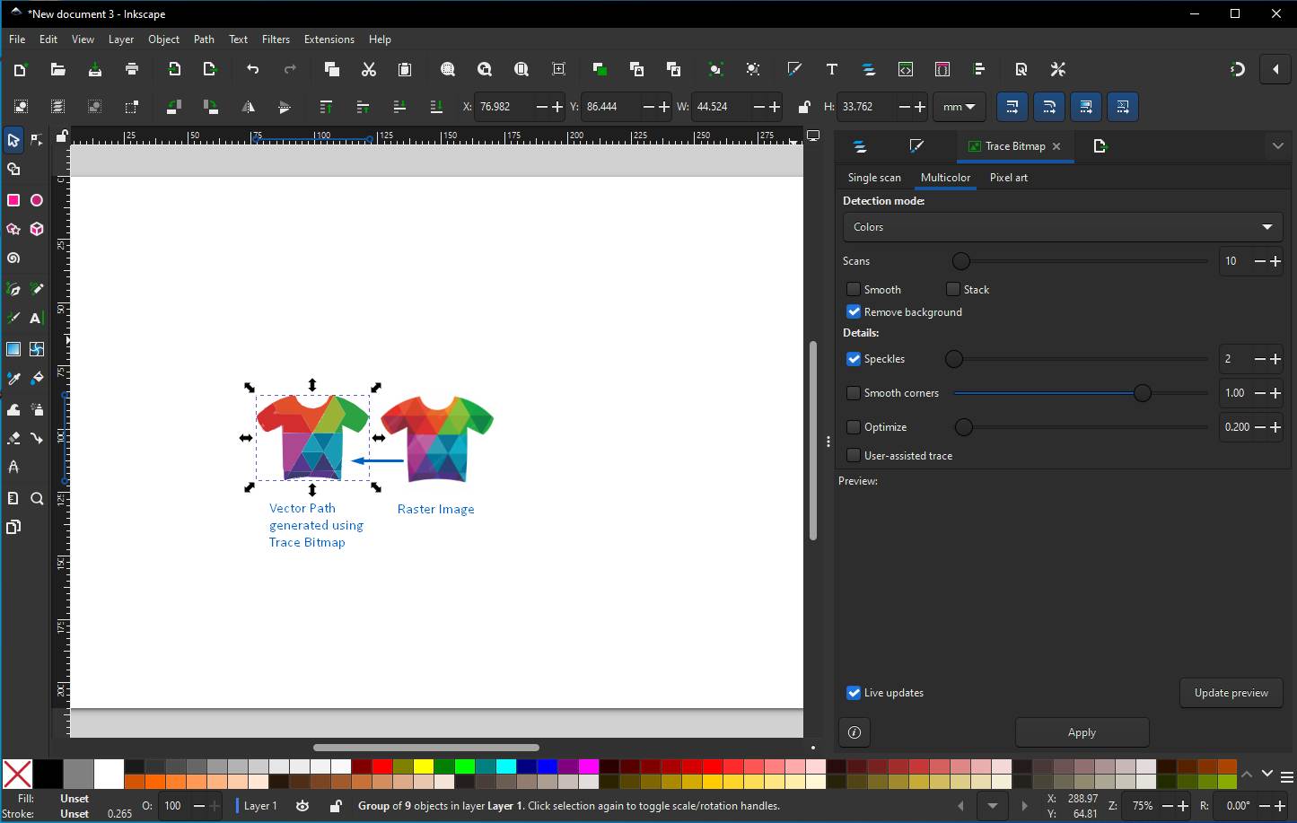
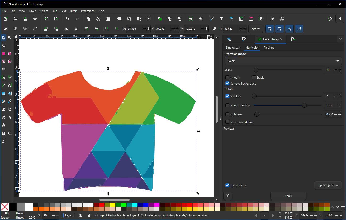
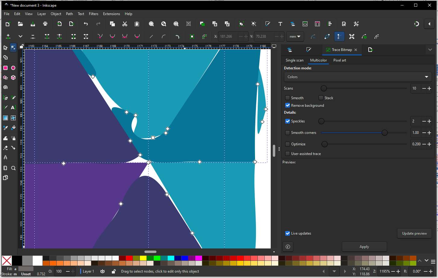
I find a inspiration image from FREEPIK, I tried to use Trace Bitmap function to convert raster image into vector path. First go to File → Import, Select PNG/JPG image then we need to convert into vector, then choose Embed, then go to Path → Trace Bitmap, a dialog box will get open in right side, I want my logo to be colorful so I selected Multiple Scans → Colors, then set the number of scans, Click Apply. Inkscape creates a vector copy on top of the original image, move the traced object slightly, delete the original raster image underneath, go to File → Save As, choose SVG (best for Fab) Or export as DXF for laser cutting.
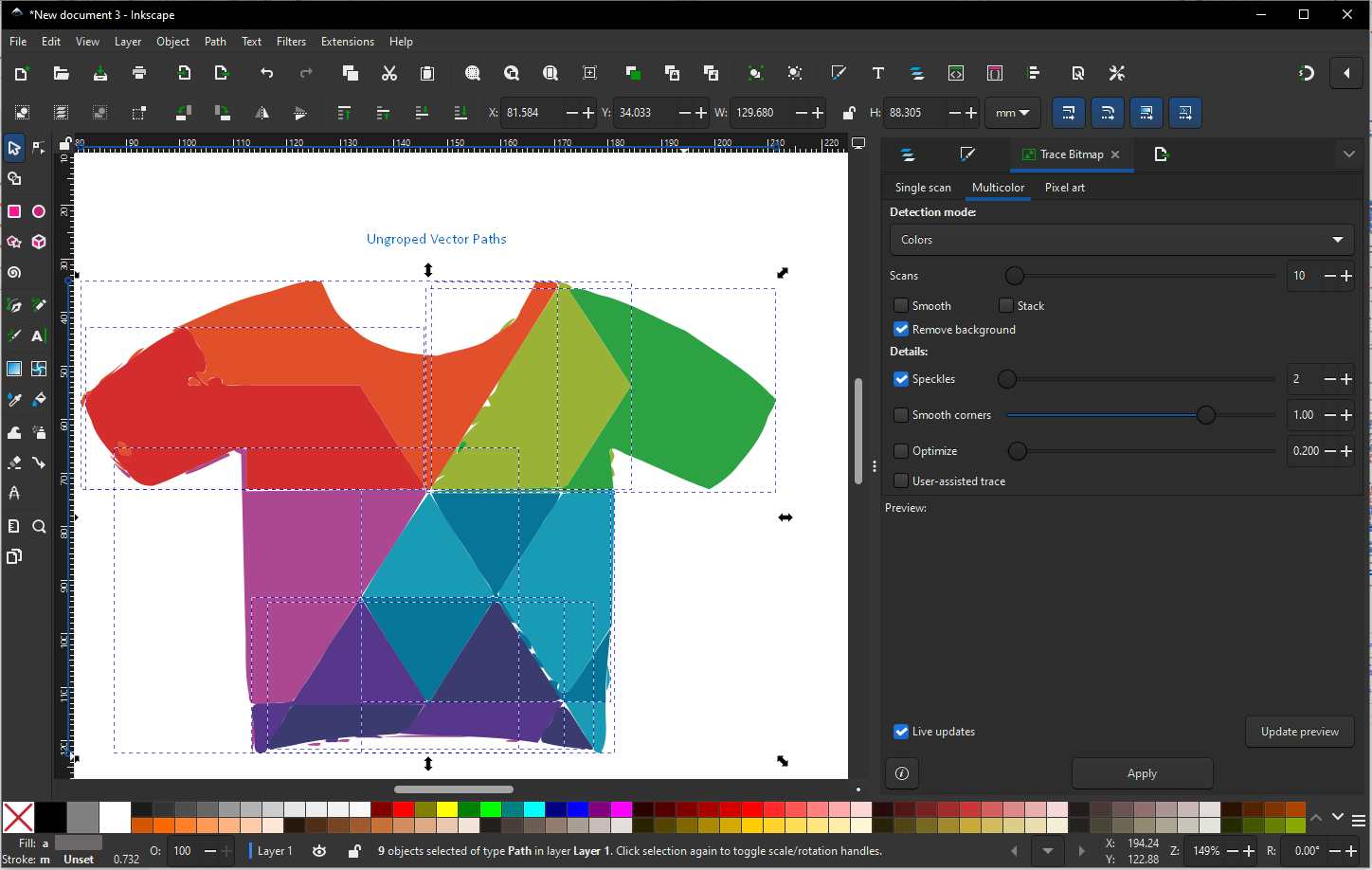
We can see that there are some distortion paths which need to be clean up. Simplify paths function can help reduce the distortion, click Path → Simplify.
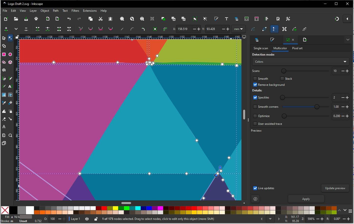
The Node Tool lets us Edit individual nodes (points) on a path, it let us adjust segments between nodes and lets us clean messy vector edges without changing shape intent. Select the traced vector and make sure it’s un-grouped (Object → Ungroup), press N to apply node tool, we will see nodes - small squares and path segment connecting them- now we can select nodes and adjust them, delete them to clean up the Logo.
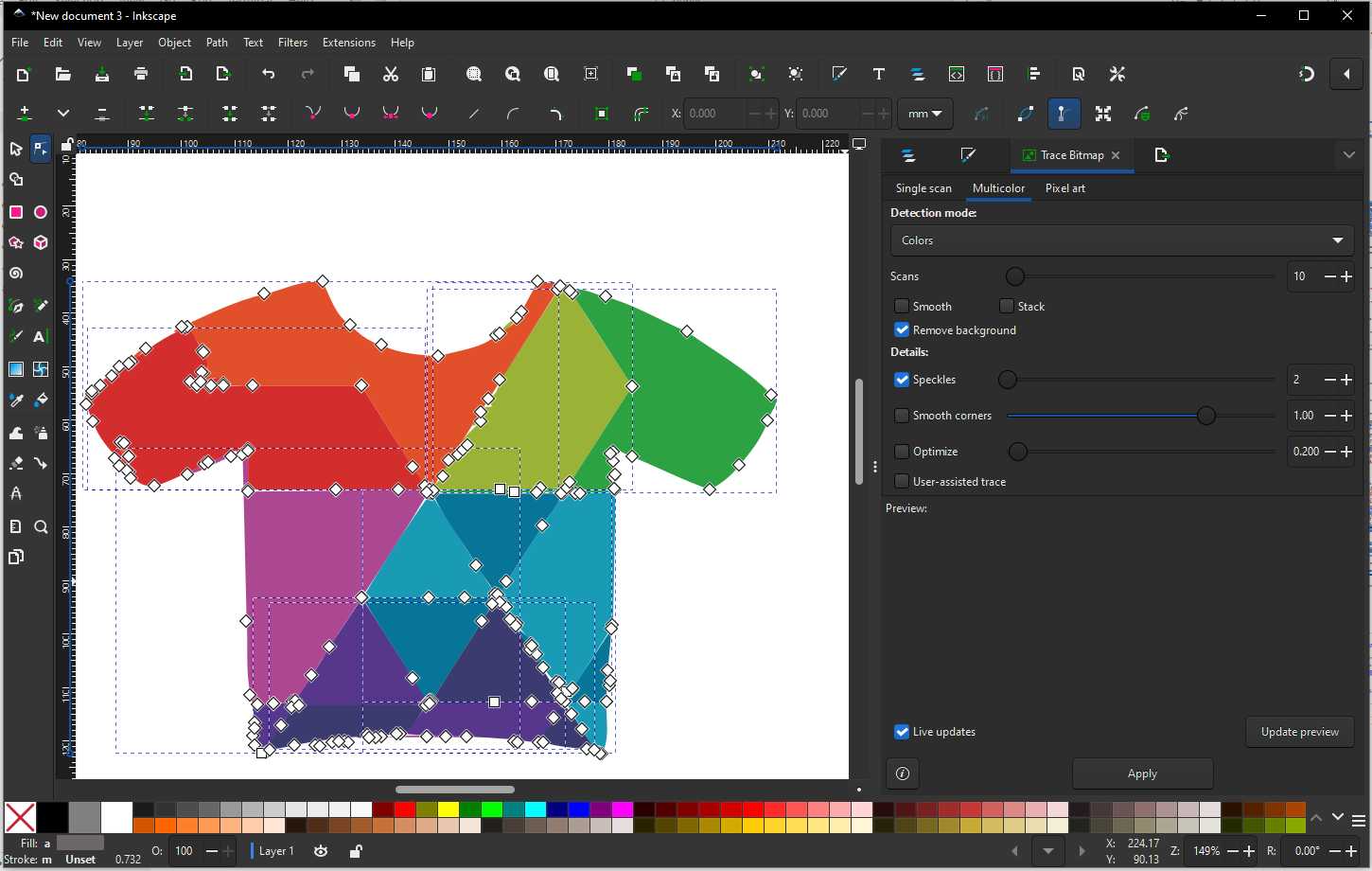
We can see the difference between above one and below one.
Now to complete the logo, I added Rangbharu (meaning - "festive friends," or "companions in color/joy"), the tag line and saved the file as SVG file.
GIMP
GIMP stands for GNU Image Manipulation Program. GIMP is a free, open-source image editing software, similar to Adobe Photoshop, used for photo editing, graphic design, and image manipulation.
So during my Fab Academy, I can use GIMP for editing photos, cleaning screenshots, removing and changing background from project photos, and preparing images for weekly documentation, reducing image size without losing clarity.
Here is comparison between GIMP and Inkscape.
| Feature | GIMP (Pixel surgeon) | Inkscape (Vector architect) |
|---|---|---|
| Best for | Raster images (photos, screenshots) | Vector graphics (logos, icons, line art) |
| Use for | Remove or change image backgrounds, Edit photos from your phone/camera, Clean up screenshots, Adjust brightness, contrast, colors, Export transparent PNGs for websites, Compress images without losing clarity | Design logos, icons, symbols, Create laser-cut or vinyl-cut files, Make scalable graphics that don’t lose quality, Convert sketches into clean outlines, Prepare SVG/DXF files for fabrication. |
| Fab Lab use | Documentation | Manufacturing |
| Image type | JPEG, PNG | SVG, DXF, PDF |
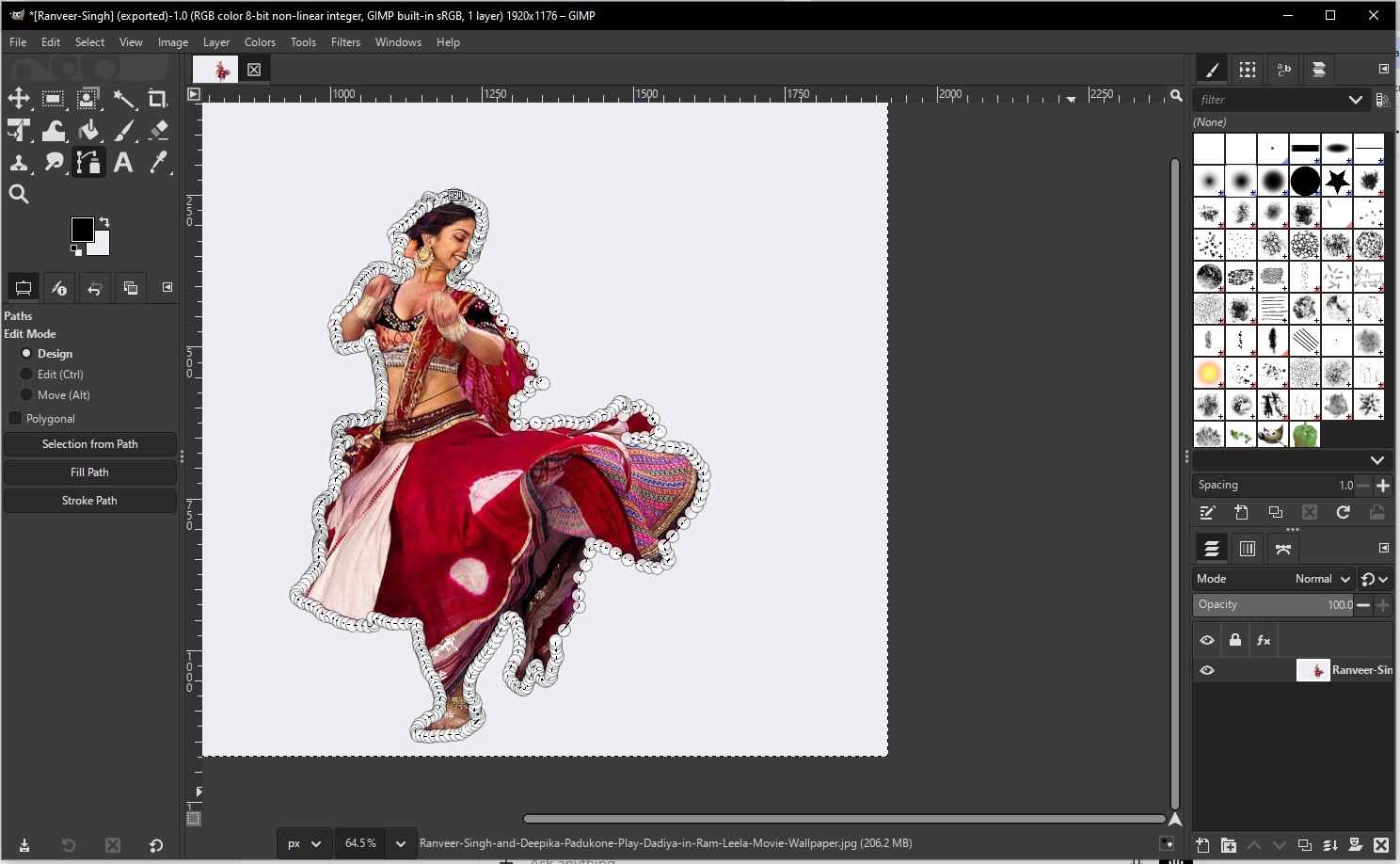
Now lets try some photo editing with GIMP. Below is an image (Image Source) from an Indian movie. As shown in the below screenshot open image in GIMP by File → Open and select image. Add Alpha Channel (very important) Layer → Transparency → Add Alpha Channel. This allows transparent backgrounds.
Now select Foreground Select Tool, Tool icon looks like a person with dotted outline, Shortcut: Shift + G, or we can find it under tools -> select tool -> Foreground Select Tool. Roughly outline the subject - draw a loose outline around the object you want to keep and then press Enter. this did not worked because it was asking to paint inside the selected part and if I select brush the earlier step was undone.
So I tried using Fuzzy Select tool, select Fuzzy Select Tool under Tool Tab (Shortcut: U) Click on background areas which all you want to remove, adjusted the threshold and pressed Delete.
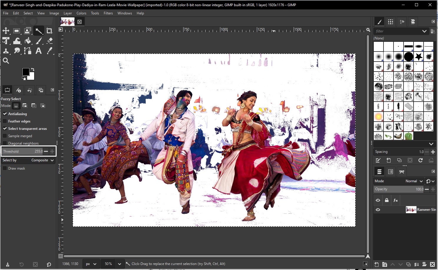
The output of fuzzy select tool was not that accurate. So next I tried doing it with Paths Tool (most precise but manual), select path tool under tools and trace point manually.
Photopea
Using Photopea, I tried to remove background → keep subject → transparent background (no background) → paste over another image. First I open Photopea then opened the image that I want to make No-background, now to unlock the background layer, I double-clicked on background and click OK - this converts it to a normal layer and enables transparency. Now I used Magic Cut tool (under select tab) then paint over the subject you want to keep, and clicked OK - Background is removed automatically. we should see a grey checkerboard pattern, this means the background is gone.
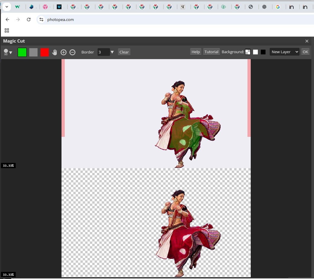
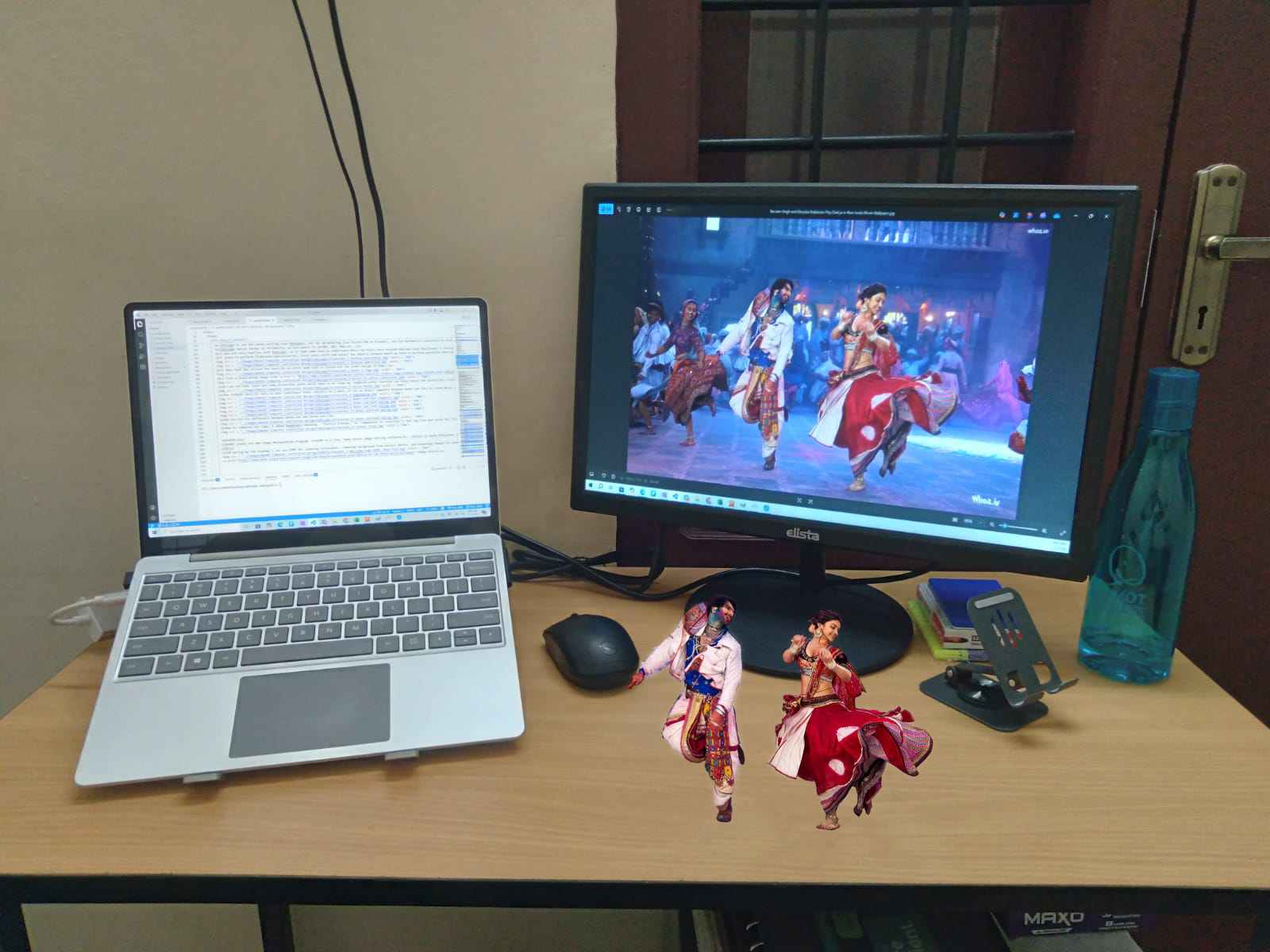
To paste on top of another image, File → Open → open background image, copy and past the edited image and click Transform controls to resize and adjust.
Now I tried to make a Poster for my Project. I tried to open SVG file in photopea however the font style got change so, so I first converted the SVG file into PNG file and then open in Photopea.
3D Design Types and Approaches
Modern 3D design tools support different ways of representing, creating, and managing complex geometry. Understanding these concepts helps in choosing the right tool and workflow for fabrication, simulation, and collaboration.
- History-Based CAD
- Go back to earlier steps
- Modify parameters
- Automatically propagate changes through the entire model
- Design Management and Collaboration
- Geometry Representation
- It is a mathematical description of an object’s boundary
- Commonly used in CAD and fabrication tools
- Can struggle with very complex or poorly defined geometry
- Errors in surfaces may cause tool crashes or invalid models
- The object is described implicitly (e.g., “inside” or “outside” a function)
- Useful for complex, organic, or procedural shapes
- Less common in traditional CAD, but powerful in research and advanced modeling
- Used in simulations and medical imaging
- CT scans are a classic example of volume representation
- Ideal for physical simulations (stress, heat, material behavior)
- Not always suitable for direct fabrication without conversion
- 3D Input Methods
- 3D mice
- VR interfaces
- Specialized input devices
- Design Interfaces: From GUI to Code
- Graphical User Interfaces (GUI)
- Scripting
- Hardware Description Languages (HDL)
- Design Paradigms
- You explicitly define how to build the object
- Example: sketching, extruding, clicking, dragging
- Common in traditional CAD tools
- You define what you want, not how to build it
- The system determines the steps
- Often used in parametric and rule-based modeling
- You specify goals and constraints (e.g., “make a table that supports X load with minimum material”)
- The software automatically generates optimized forms
- Results are often organic and mass-efficient
- Autodesk and others have done significant work in this area
- The system handles constraints instead of the designer manually resolving them
- Multidisciplinary Design Optimization
- Structural forces
- Aerodynamics
- Thermodynamics
Powerful CAD tools maintain a design history, meaning every operation is recorded step by step. This allows designers to:
This approach is essential for iterative design and engineering workflows.
In real-world projects, multiple people often work on different subsystems, different version of the same model. CAD tools therefore need mechanisms for version control, collaboration, managing dependencies between parts and assemblies. This becomes critical in large or multidisciplinary projects.
Boundary Representation (BRep)
BRep represents objects using their surfaces, edges, and vertices.
Functional Representation (FRep)
Instead of describing surfaces, FRep defines geometry using mathematical functions.
Volume Representation (VRep)
VRep represents objects as volumetric elements (voxels) — essentially pixels in 3D.
As designs become more complex, using a standard mouse and keyboard can become limiting.
Advanced workflows may use:
These allow designers to interact with models in three dimensions, rather than translating 3D intent through 2D input.
Clicking, dragging, and sketching — ideal for beginners and simple designs.
As designs grow complex, repetitive GUI actions become inefficient. Scripts automate tasks and ensure consistency.
For extremely complex systems, scripting is not enough. Full declarative or descriptive languages are used to define structure and behavior at a higher level.
Imperative Design
Declarative Design
Generative Design
Many real-world systems must satisfy multiple physical constraints simultaneously.
Example: Aircraft design involves:
Multidisciplinary Design Optimization integrates all these domains to find the best overall solution. Advances in AI and computation are rapidly expanding what is possible in this space.
Blender
I follow instruction from our lab instructor and tutorials of from Mr. Rico Kanthatham, which he shared during regional review, to tryout basic 3D modeling and animation in Blender.
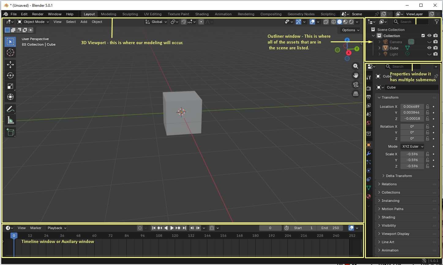
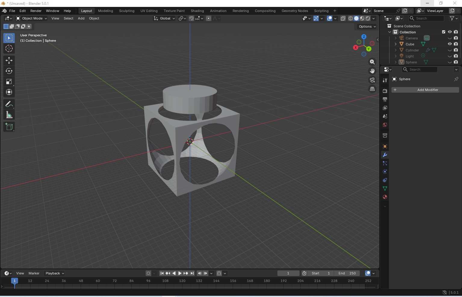
3D Viewport -The main workspace where modeling, transforming, and visualizing objects takes place. Outliner - Displays a hierarchical list of all objects in the scene. By default, a new scene contains Camera, Cube, and Light. Properties Panel - Contains multiple tabs to control object properties, including transforms, materials, modifiers, render settings, and scene options. Timeline - Used for animation control, allowing you to manage frames, keyframes, and playback.
Most of the time we will be in wireframe or solid shaping viewport, the material and rendering viewports are used in the later part of the modeling. These are on the upper right corner for 3D viewport view.
Most of the time while working in Blender, we primarily use the Wireframe or Solid viewports, as these modes are best suited for modeling and shaping objects. The Material Preview and Rendered viewports are typically used later in the workflow to check surface appearance, lighting, and final visual quality.
Blender uses simple yet powerful transformation commands. The G key (Grab) is used to select and move objects, and pressing Esc exits any active command. Movement can be constrained along a specific axis using G + X, G + Y, or G + Z. The R key is used to rotate objects, and rotation can similarly be constrained using R + X / Y / Z. The S key scales objects, and axis constraints such as S + X, S + Y, or S + Z allow scaling along a single direction, making the object thinner, wider, taller, or shorter depending on the axis selected.
To add new objects in Blender, the shortcut Shift + A is used. It is important to ensure that the mouse cursor is positioned inside the 3D Viewport before adding an object, otherwise Blender may not place it correctly.
Unit settings are managed in the Properties panel. Under the Scene Properties, the Units section allows changing the measurement system to millimeters. In addition to this, the unit scale and grid display must also be adjusted in the viewport overlays so that the grid reflects 1 mm spacing, which is especially important for fabrication-oriented designs. Pressing the N key opens the Transform panel in the viewport, where precise values for location, rotation, scale, and object dimensions can be viewed and edited.
The Modifiers panel, represented by the blue wrench icon, allows non-destructive operations on objects. One commonly used modifier is the Boolean modifier, which enables combining or subtracting shapes. To merge two objects, a Boolean modifier is added, the Union operation is selected, and the second object is chosen using the eyedropper tool. Initially, dark or black patches may appear because the original object still exists in the scene. Hiding or disabling the original object removes these artifacts. Although the combined object may appear as a single shape visually, it will not behave as one until the Boolean modifier is applied. Once applied, moving the object using G moves the entire merged geometry together.
To cut material from an object, the same Boolean workflow is used with the Difference operation. For example, adding a UV Sphere using Shift + A, positioning it appropriately, and applying a Boolean Difference modifier results in a spherical cut through the base object. Once confirmed, applying the modifier permanently removes the intersecting volume, completing the cut.
Now, let's model the enclosure that fits inside the pocket to hold our electronics and battery. You can use Shift + D to duplicate any parts. To smooth out those sharp corners, hit Tab for Edit Mode and press 2 for edge selection. A quick tip: hold Alt while clicking an edge to grab the whole loop instantly. Use Ctrl + B to pull a chamfer, and just scroll your wheel if you want to turn it into a fillet. Finally, hop back into Object Mode and hit Shade Auto Smooth to make it look polished.
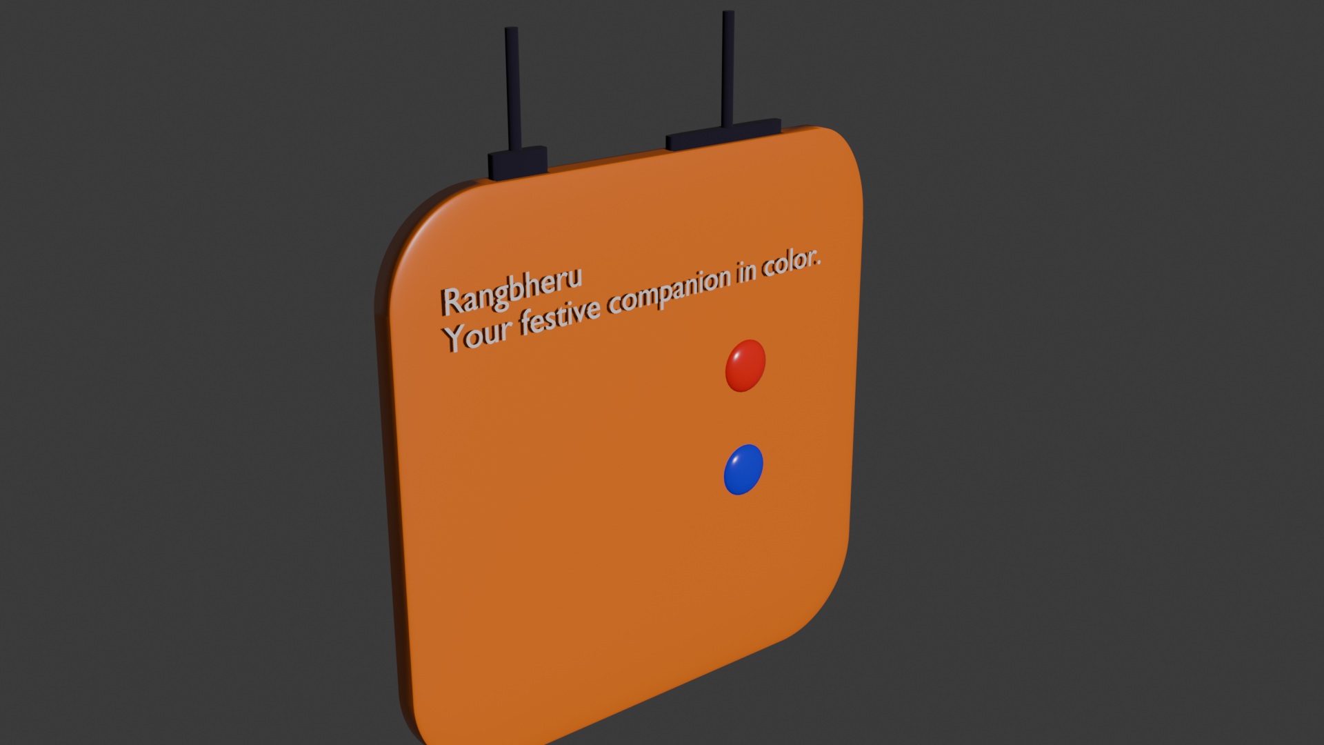
To begin rendering in Blender, the first step is to assign a material to the object. Select the object and go to the Material Properties panel in the bottom-right corner (represented by a sphere icon). Create a new material, give it a name, and use the color selector to choose the desired surface color. Enabling the Material Preview mode allows you to immediately see how the material appears on the model.
Lighting plays a key role in achieving a realistic render. Using Shift + A, an Area Light can be added to the scene. Area lights are especially useful because they can be scaled in size to produce soft, diffused lighting, resulting in smoother shadows and a more natural look compared to point or spot lights.
For high-quality rendering, open the Render Properties panel (camera icon on the right side). Blender’s default engine is often set to EEVEE, which is fast but less physically accurate. Switching to Cycles provides more realistic lighting and shadows. If your computer has a compatible graphics card, enabling GPU rendering significantly speeds up the rendering process.
Now let’s move on to animation in Blender. First, ensure that all parts you want visible in Frame 1 are turned on by enabling both the eye icon (viewport visibility) and the camera icon (render visibility) in the Outliner. Any parts that should not appear in Frame 1 should have both icons turned off.
Once the scene is set, press I to insert a keyframe for the current frame. Next, move the timeline cursor to Frame 2, adjust the position or visibility of the parts you want to animate relative to Frame 1, and press I again to insert another keyframe. This process can be repeated for as many frames as needed to build the full animation sequence.
To preview the animation, click Play in the Timeline panel. If you want to capture a still image at any moment, go to Render → Render Image. To generate the full animation as a video, select Render → Render Animation. The rendered video will be saved automatically in the output folder (by default, the Downloads or specified output directory).
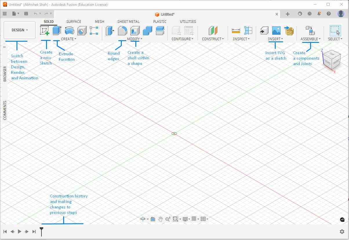
Fusion 360
During this week, I initially explored detailed 3D modeling in Fusion 360 by experimenting with various tools such as sketching, extruding, filleting, shelling, parametric features, and Boolean operations. This helped me gain hands-on familiarity with the software and understand how different design features work in practice. Although this first version became more complex than required for the assignment, it served as an important learning exercise and allowed me to build confidence in 3D modeling workflows.
After understanding the core tools and design concepts, I redesigned the model with a simpler and cleaner geometry, focusing on clarity, functionality, and manufacturability. This second iteration better aligns with the assignment objective while applying the knowledge gained from the initial detailed exploration.
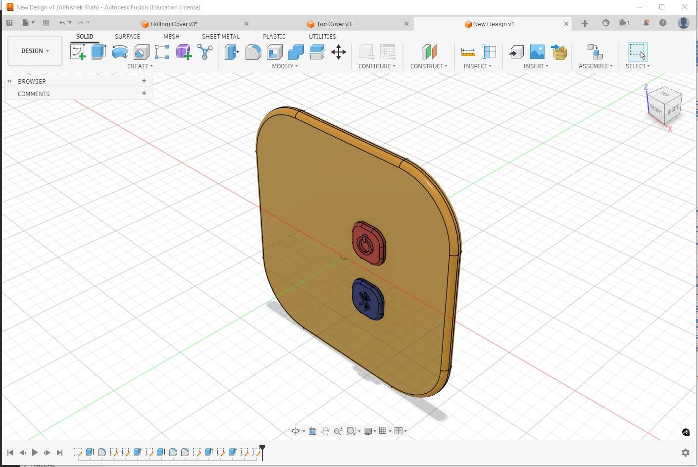
Below is the earlier detailed design process is retained below as a record of learning and experimentation, which helped shape the final simplified model.
The first software I worked with was Fusion 360. I registered on the Autodesk website, submitted the Fab Academy student verification letter to obtain a Education license, and then installed the software.
On Thursday and Friday, we received guidance from our instructor to build a basic understanding of creating 3D shapes using different modeling approaches. As part of this exercise, we designed a coffee mug, and on Friday we were introduced to parametric design in Fusion 360.
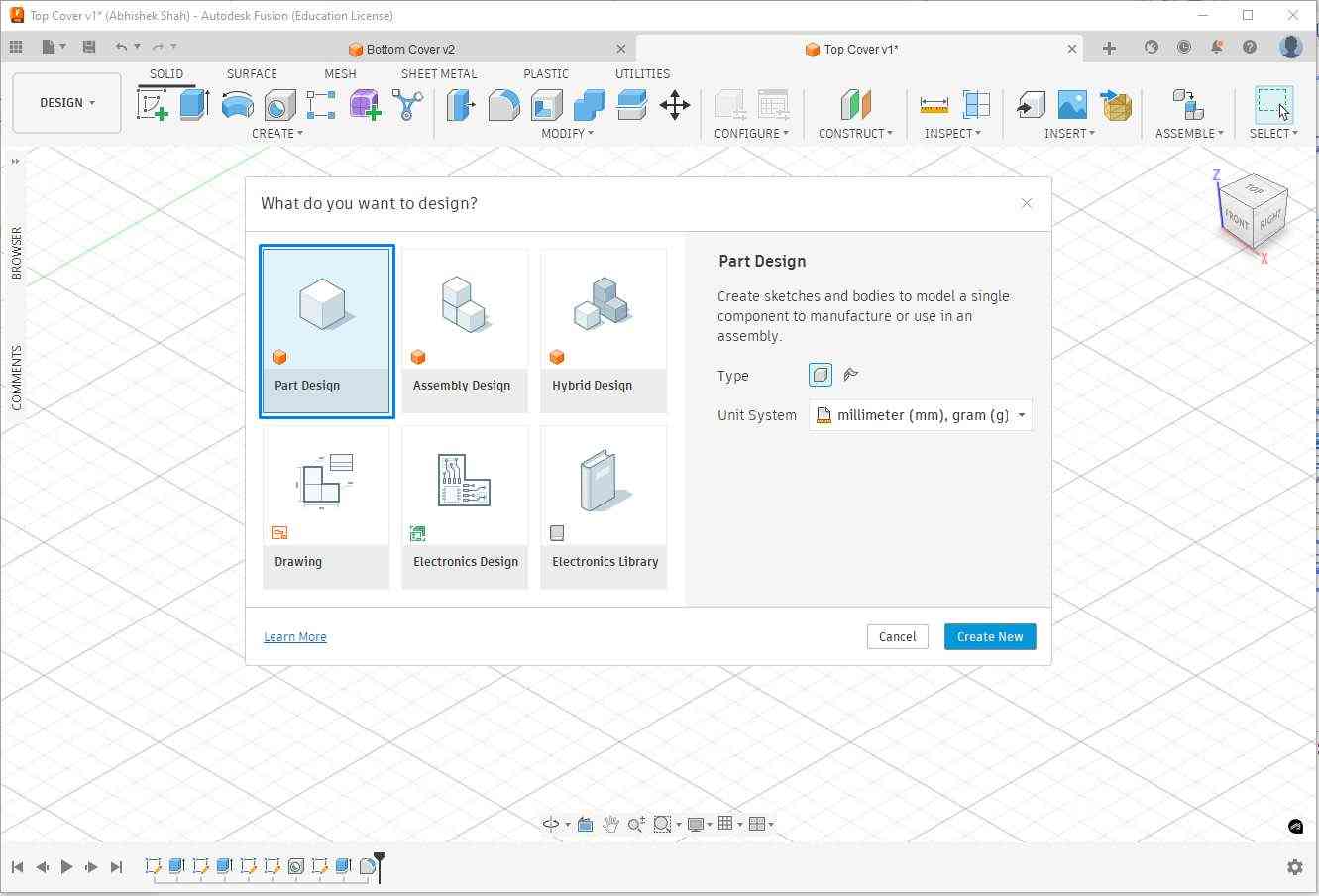
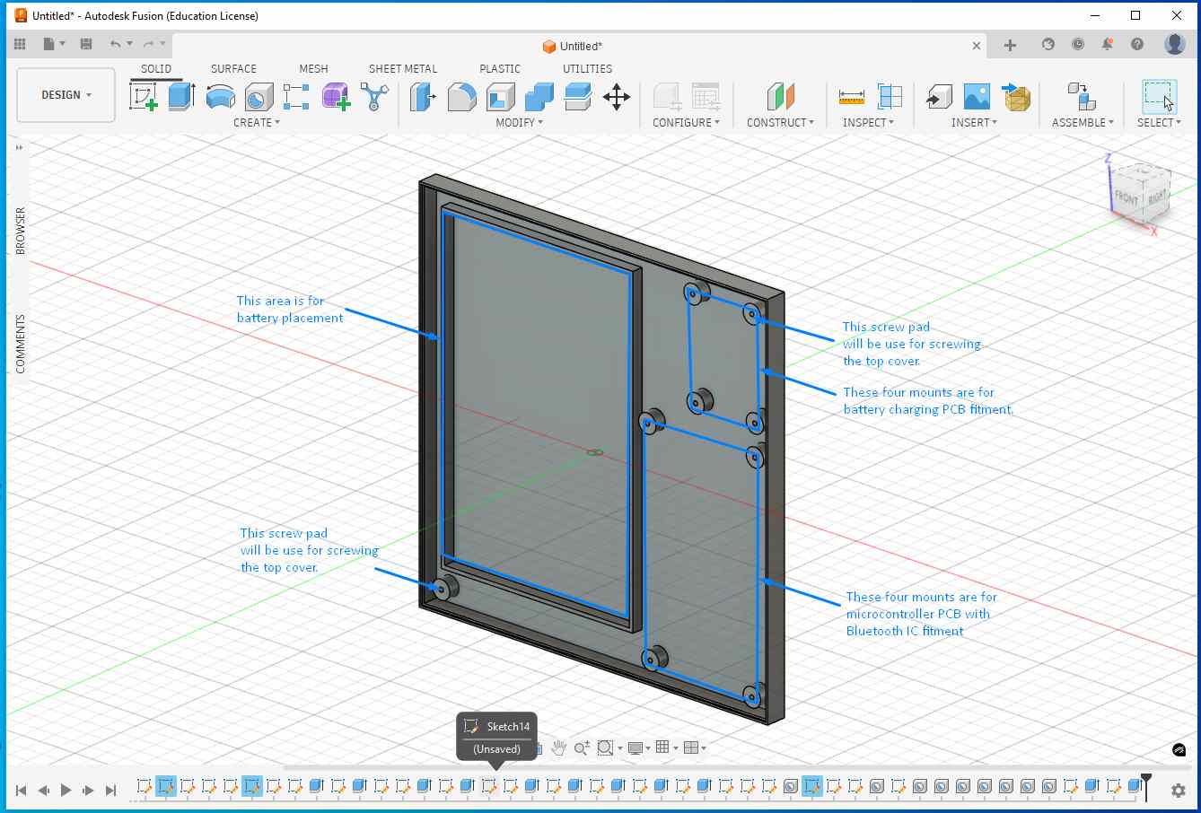
I selected part design to create an enclosure that houses the microcontroller PCB, Li-ion battery, battery charging circuit, and external connectors.
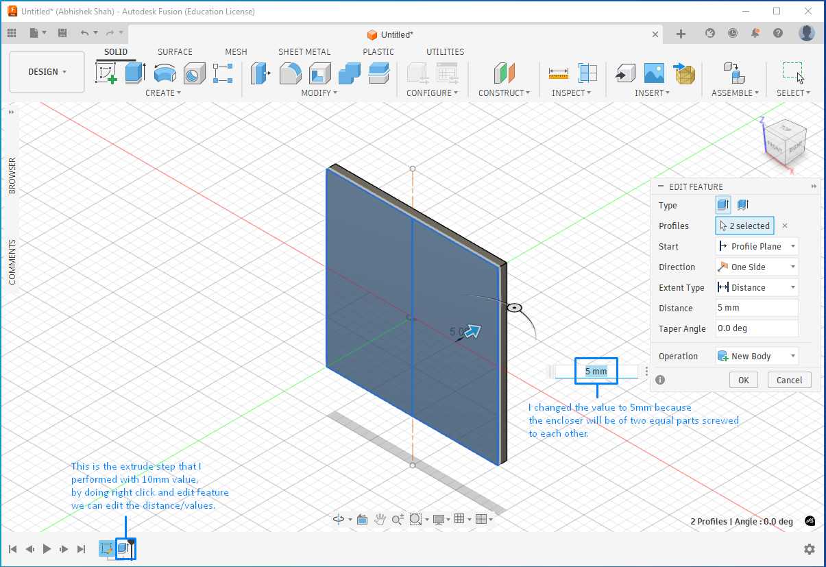
The first step was to select the reference plane on which the part would be designed. I started by creating a sketch and drawing a 100 mm × 100 mm square. After completing the sketch, I switched from the Sketch workspace to the Solid workspace and extruded the square by 5 mm to create the base solid.
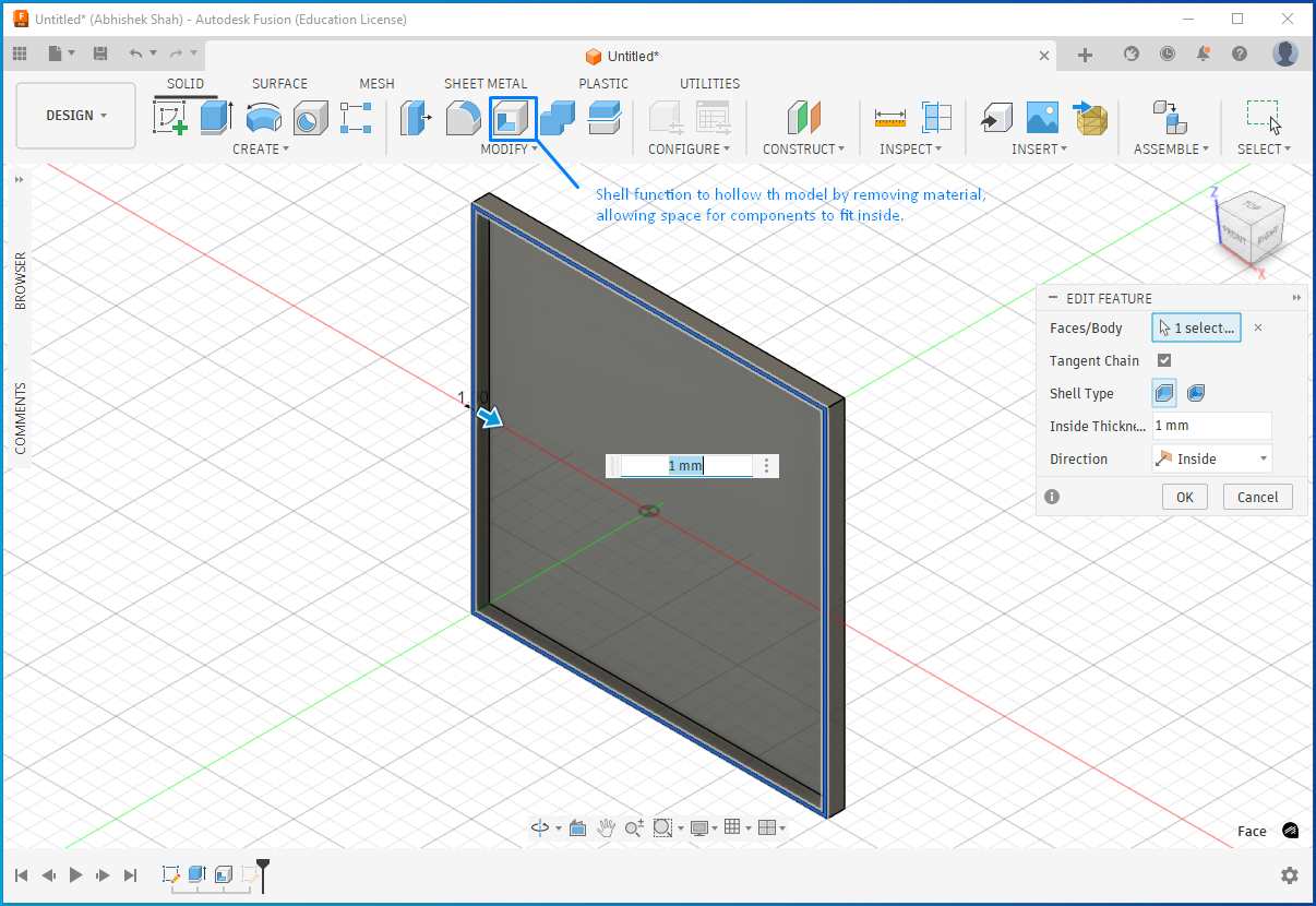
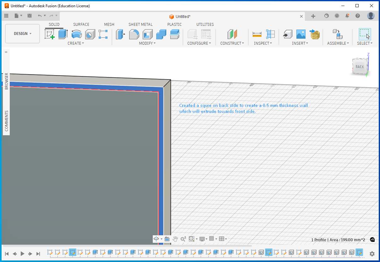
Next, I used the Shell feature to hollow the solid and remove internal material, creating space for electronic components to fit inside the enclosure. I set the wall thickness to 1 mm.
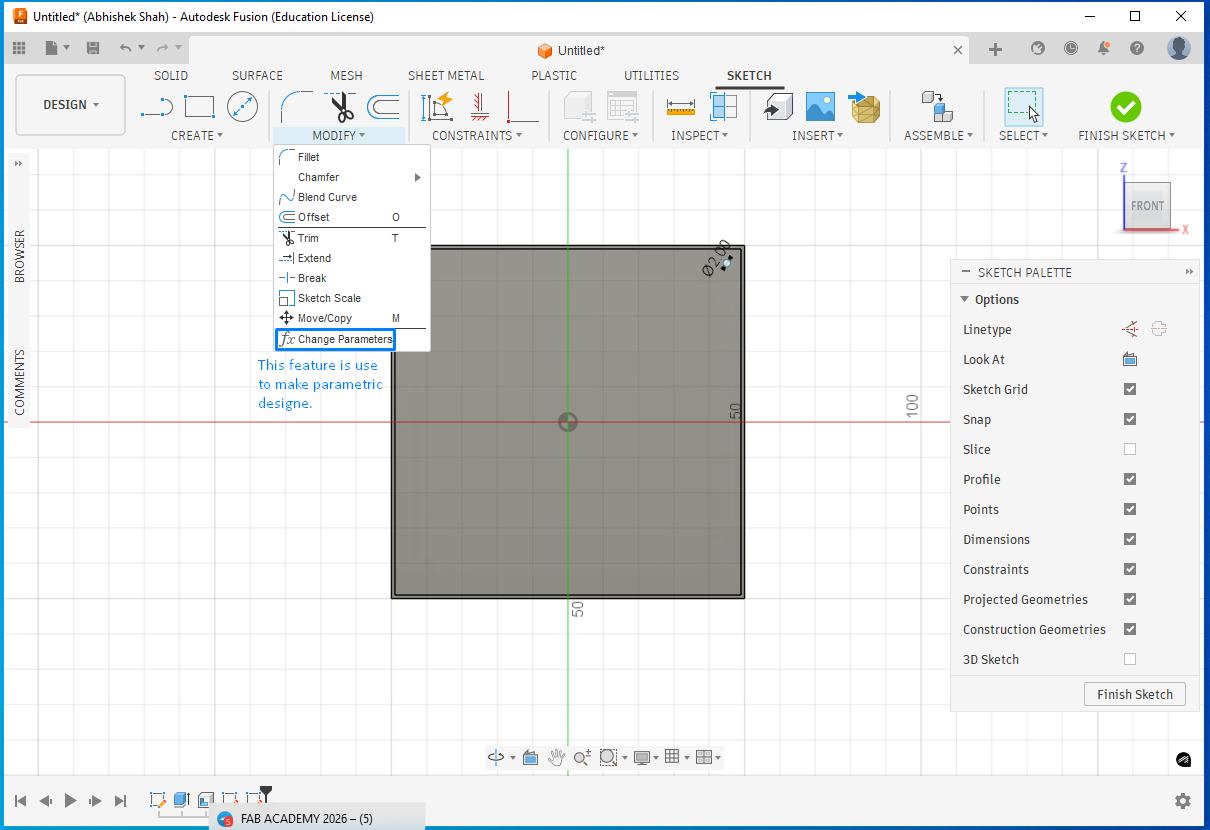
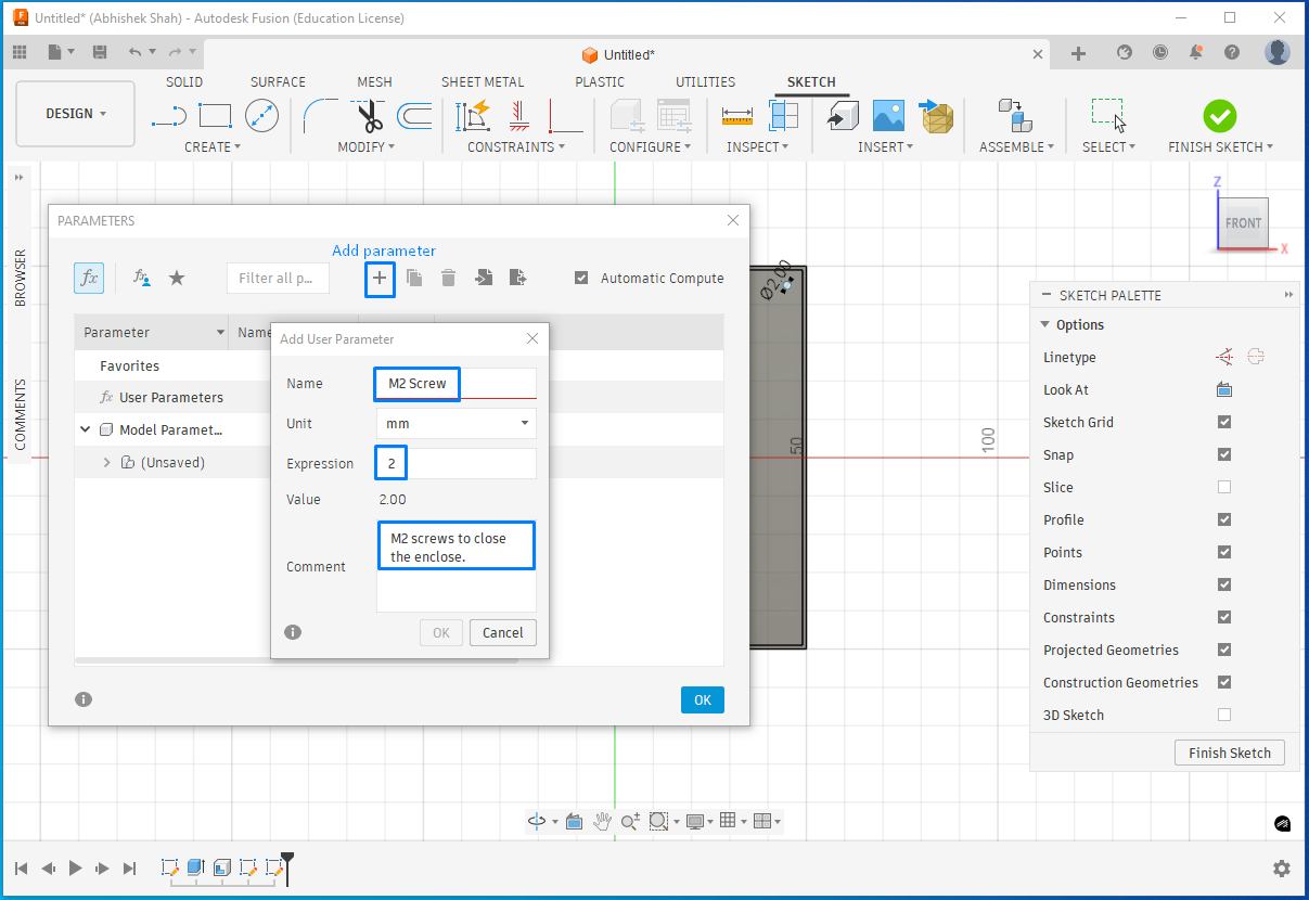
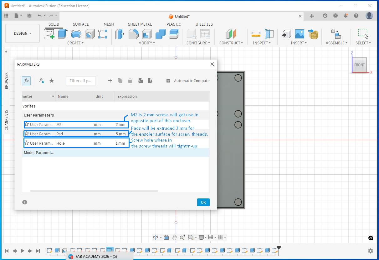
To close the enclosure, I planned to add two screws. I used parametric design so that if the screw size needs to be changed in the future, the update can be done by modifying parameters rather than editing each screw individually.
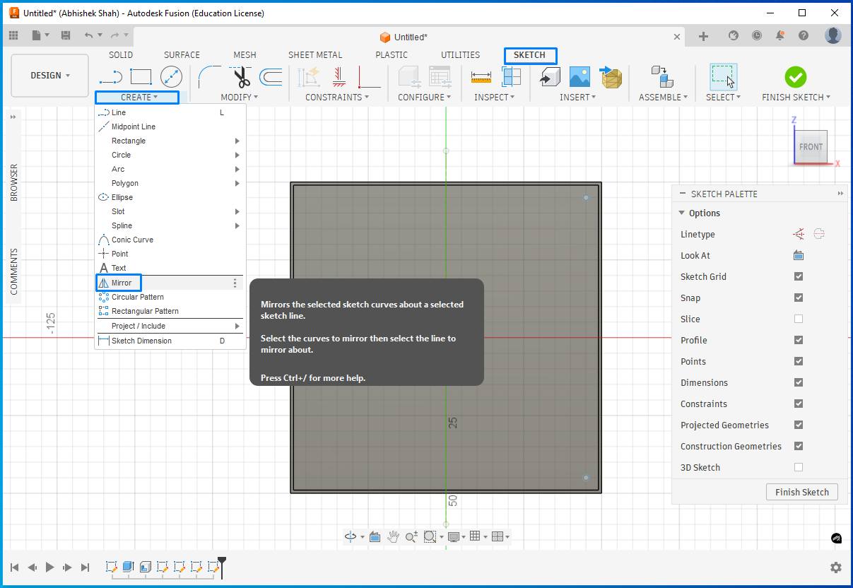
The Mirror function can be use to replicate. For this, first created a center reference line in the sketch and then used Create → Mirror to mirror the geometry across the reference line.
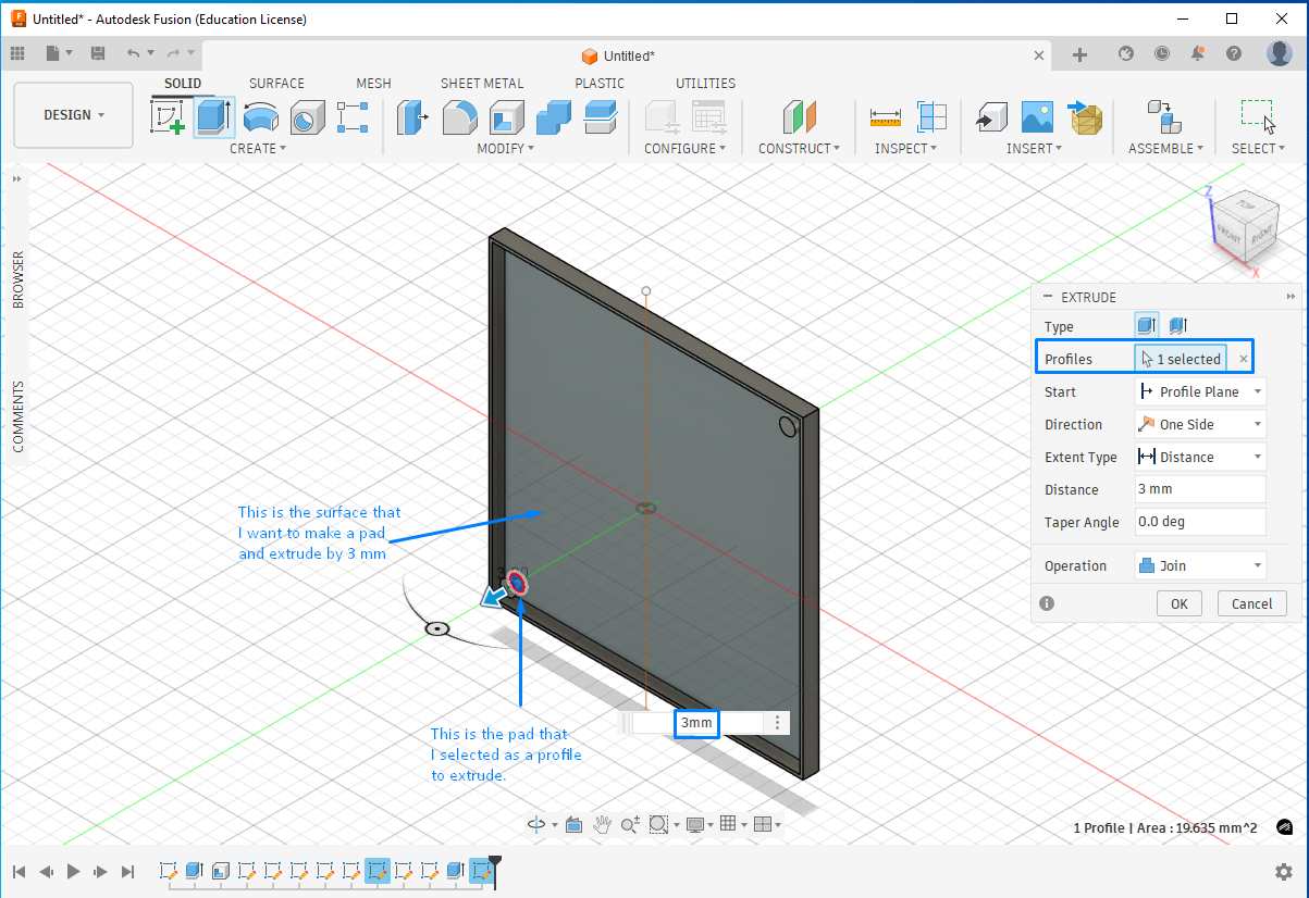
At one point, I made a mistake by selecting a plane to draw a circle instead of selecting the actual surface of the part where the feature needed to be created.
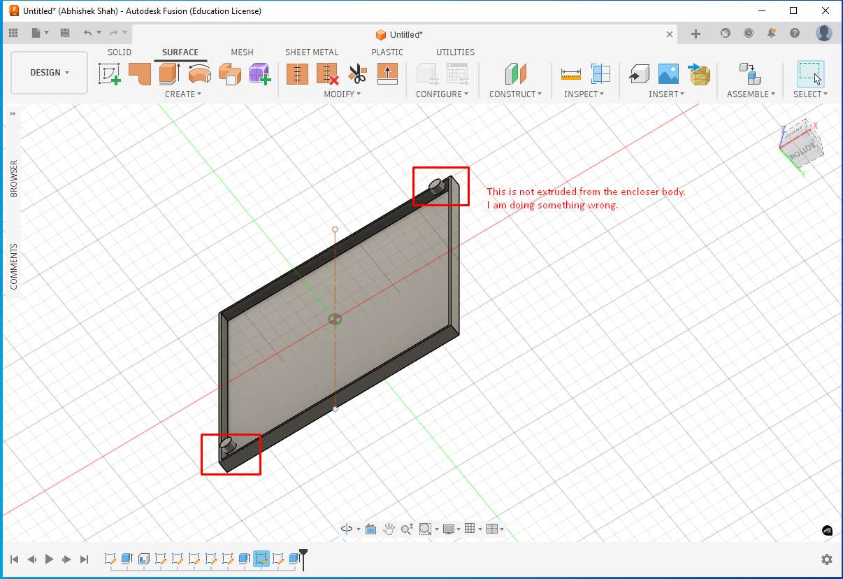
The correct workflow is:
- Select the part surface
- Go to Create Sketch
- Draw the circle
- Assign a parameter (e.g., pad)
- Switch to Solid → Extrude
- Select the pad profile and extrude it by 3 mm
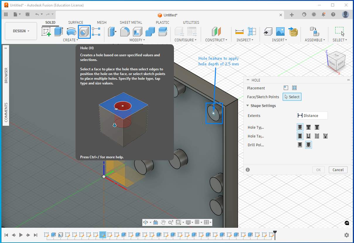
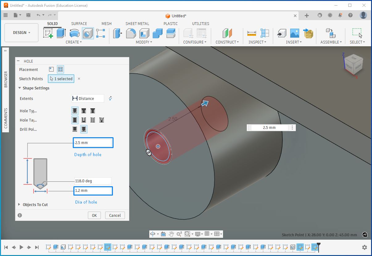
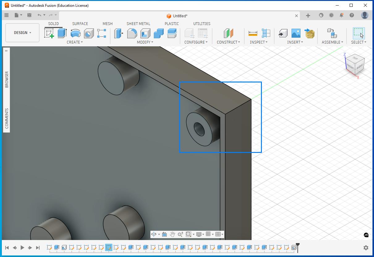
I then added another parameter for the screw hole where the threads would engage. Using the Hole feature, I created holes on the pads by specifying the hole diameter and depth, which removed material accordingly.
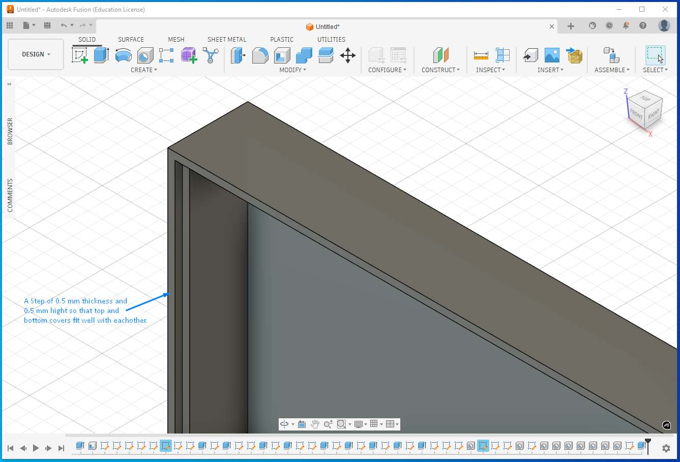
I created a step on the wall so that top and bottom encloser can fit well on each other.
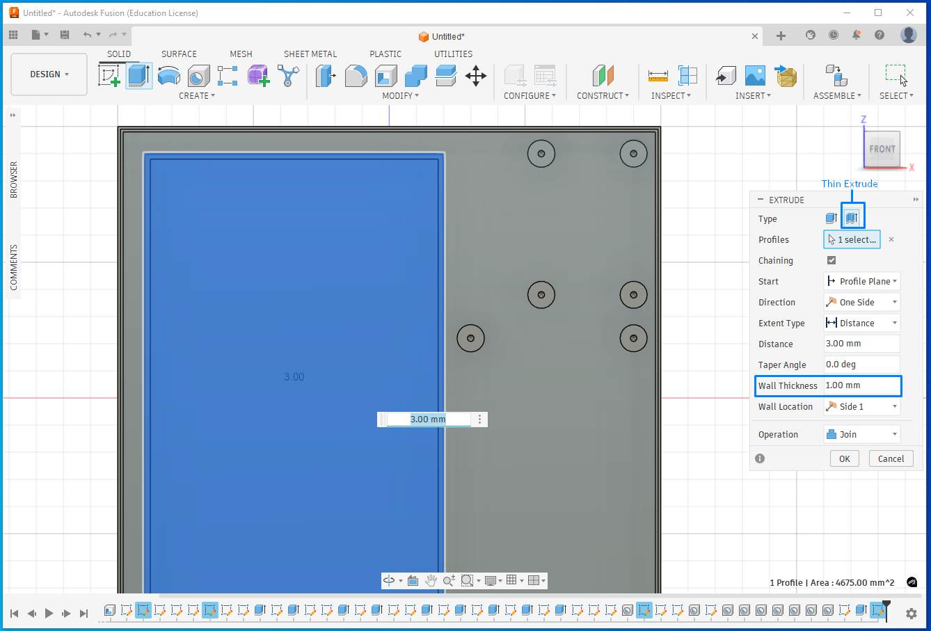
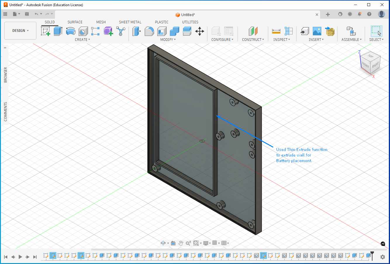
I used the Thin Extrude feature to create a battery placement area, providing a dedicated seating structure for the battery inside the enclosure.
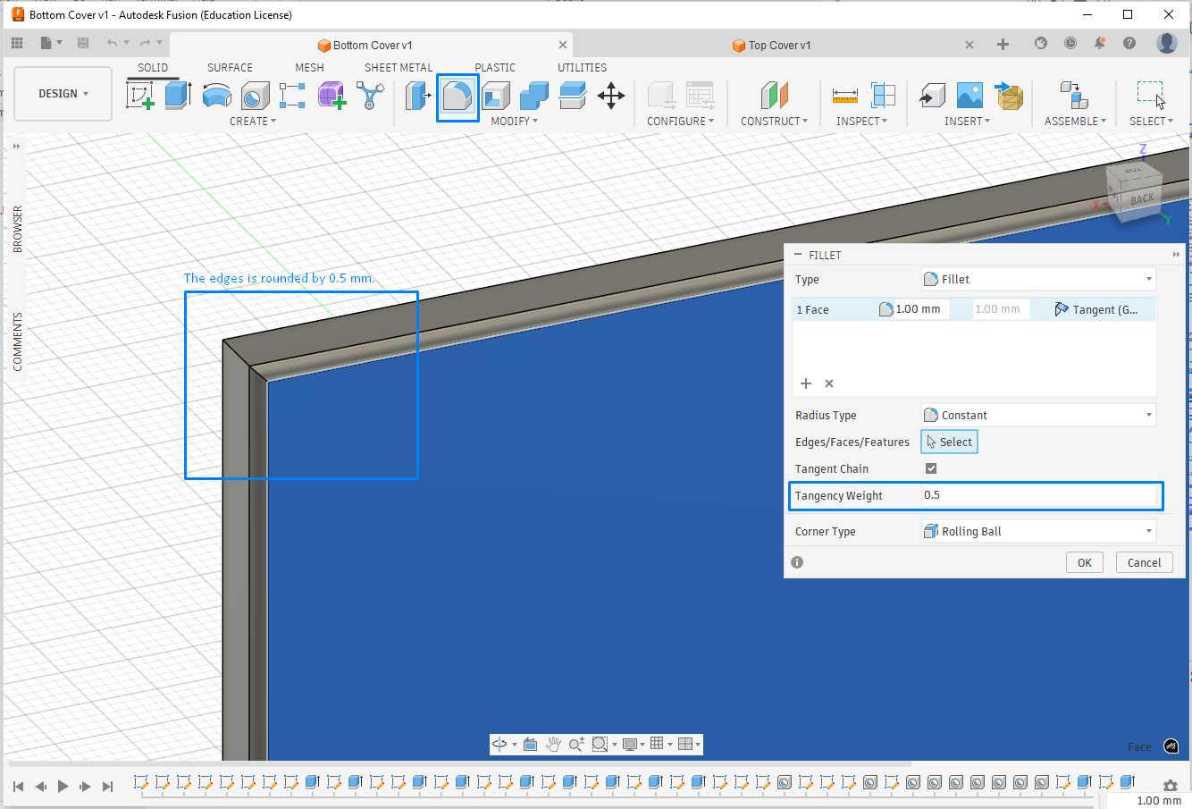
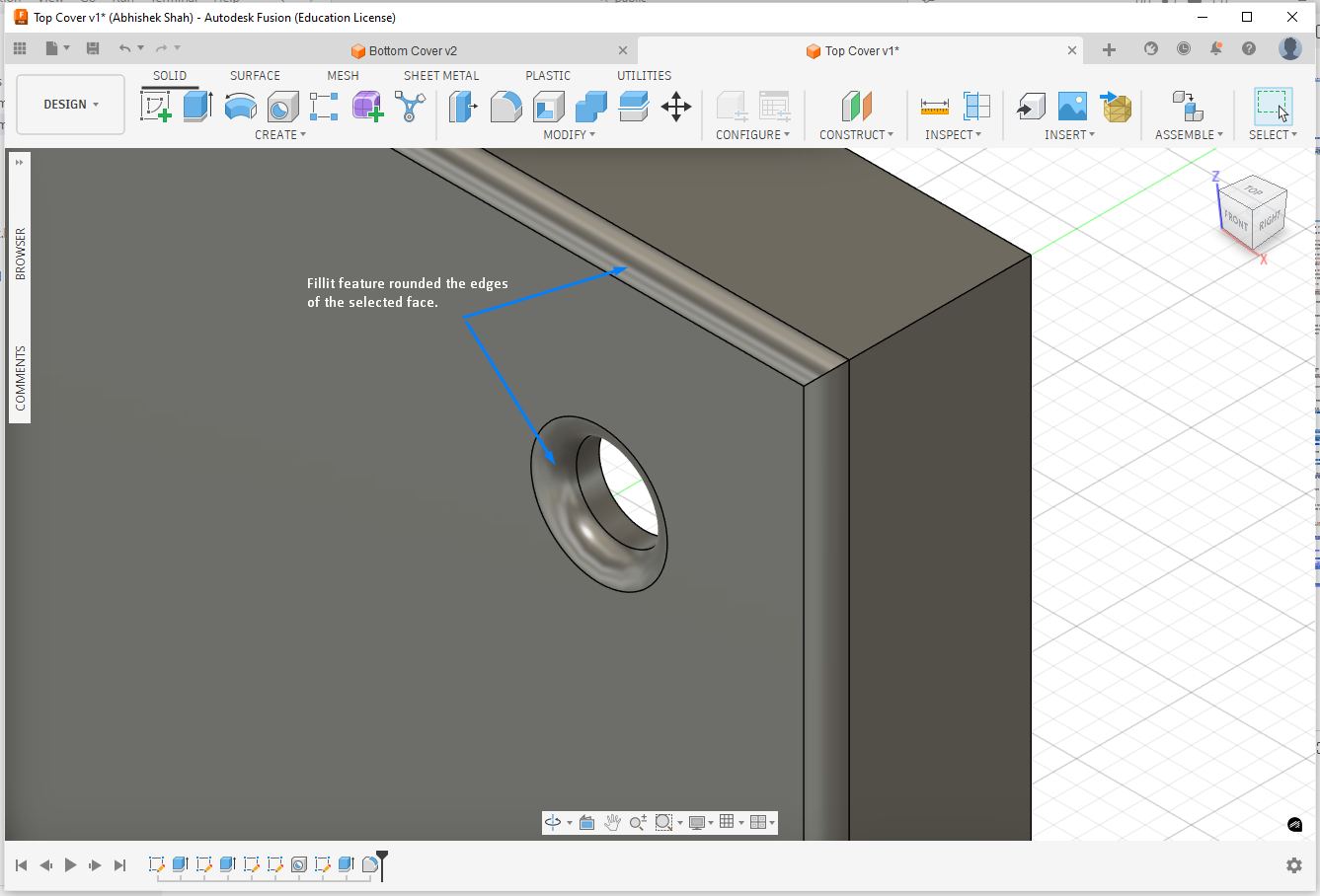
The fillit feature rounds the edges for selected face.
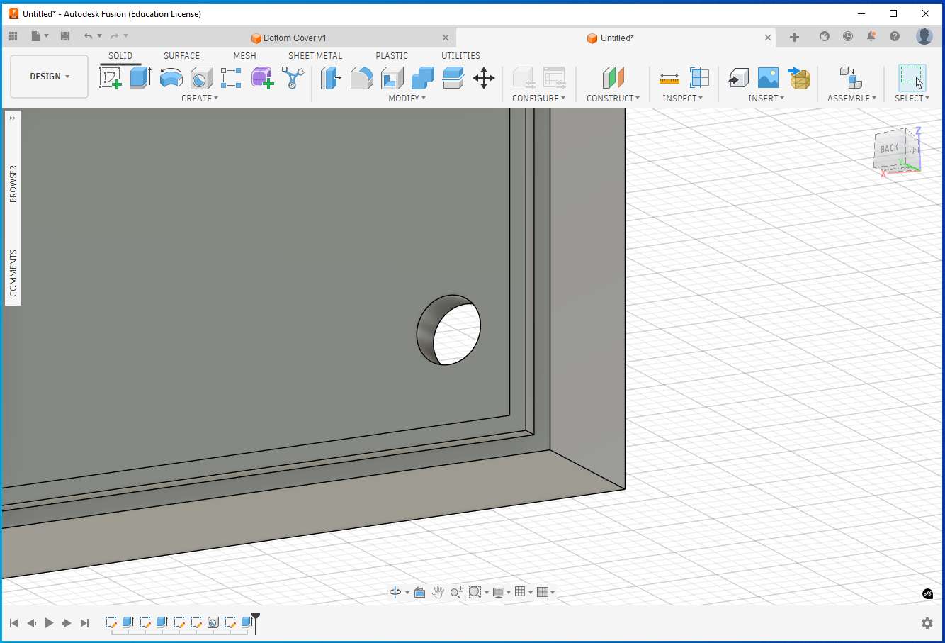
When we enter a negative value in extrude feature it automatically selects cut operation.
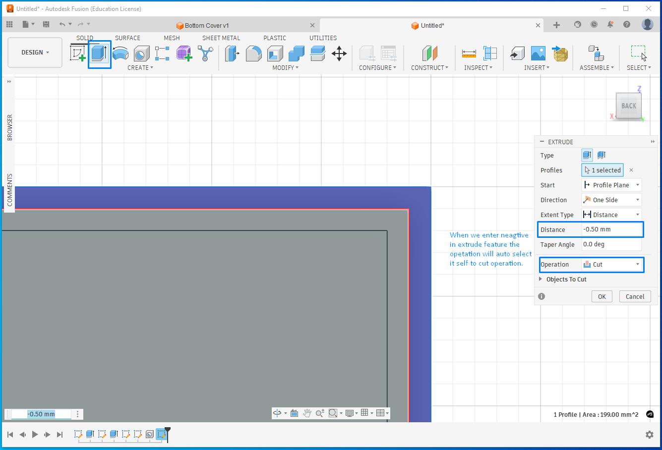
It removed the material.
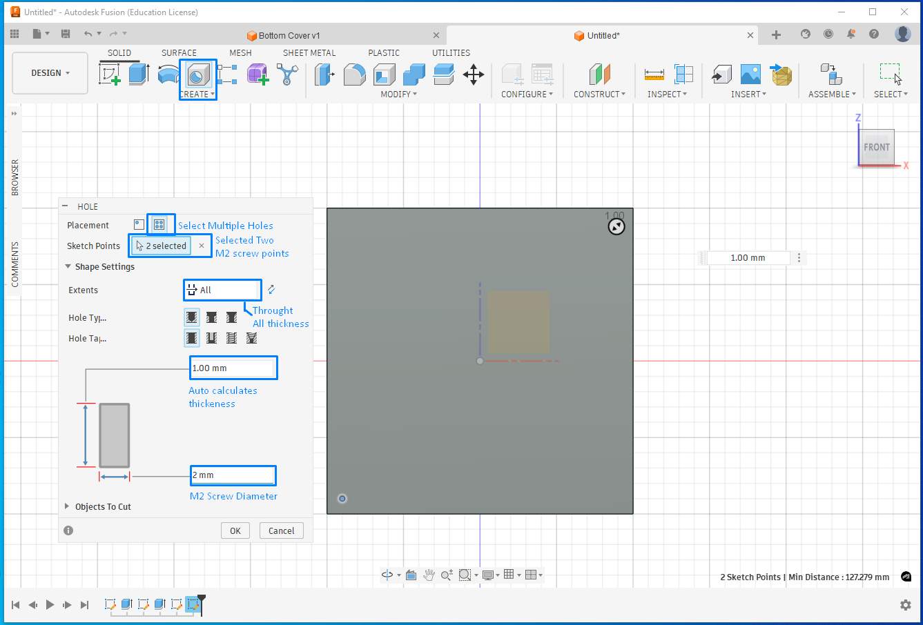
Using Hole feature to perform multiple holes together. Select Multiple Holes option, select all the points where you intend to have a hole, then select All this will through all thickness, it will auto calculate the thickness, enter 2mm for the M2 screw diameter.
The fillit feature rounds the edges for selected face.
Apply Material Properties (for mass, strength, realism) this affects, weight, density, physical simulation, and realistic appearance (partly). Go to the Design workspace, in the top toolbar, click Modify → Physical Material.
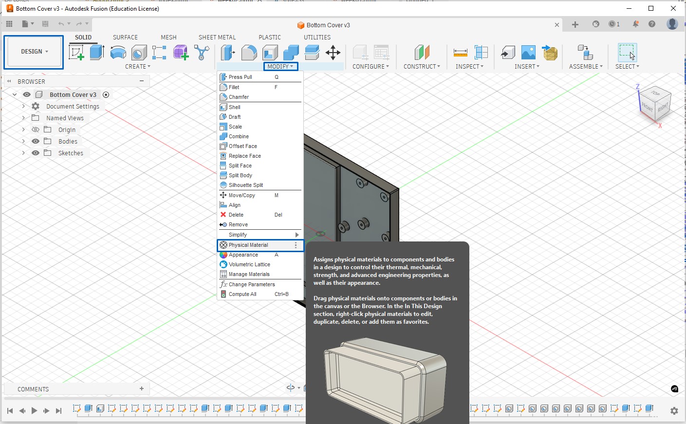
A material library panel opened up.
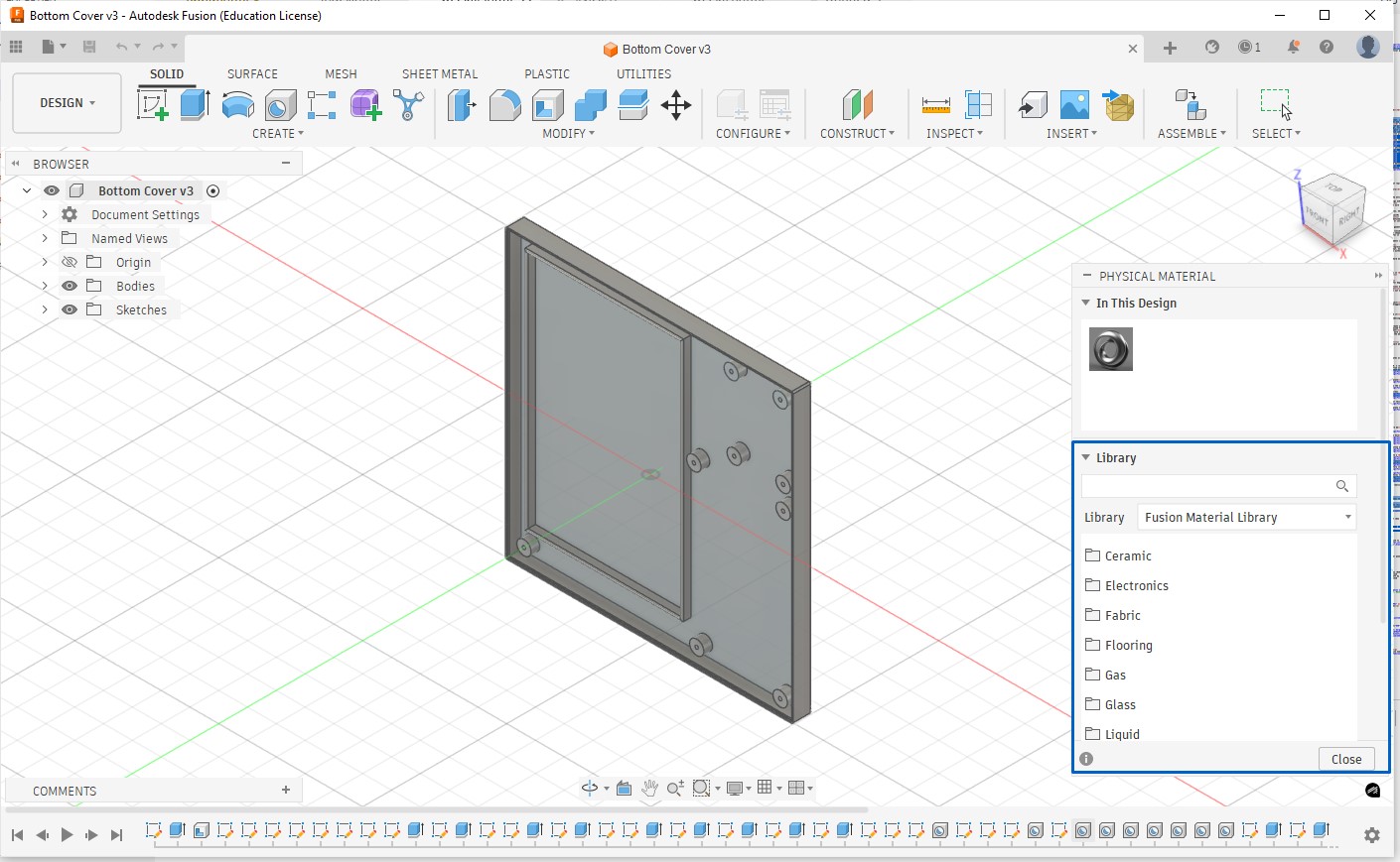
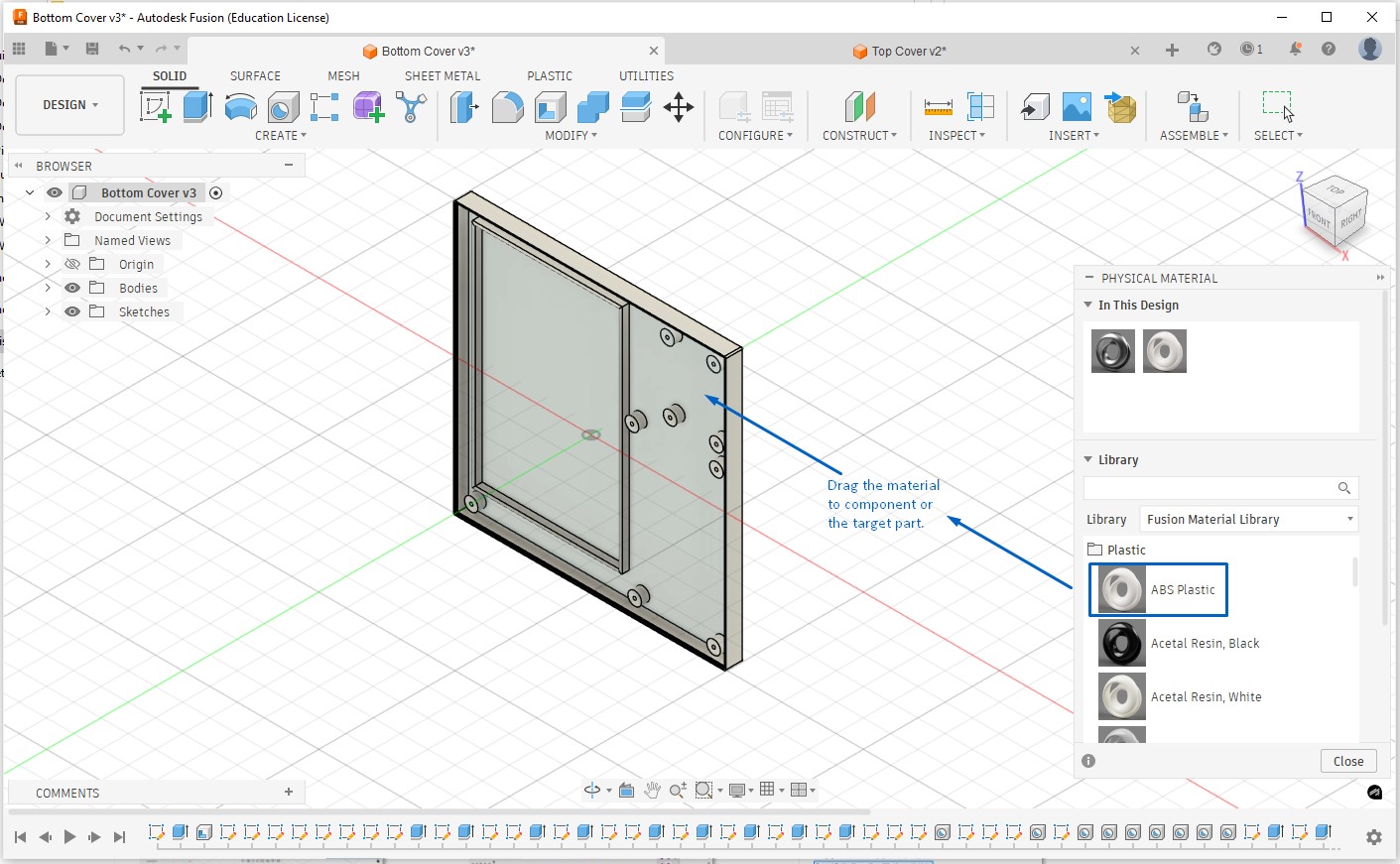
Then I choose & apply material, the list has many material categories - metals, plastics, electronics, woods, etc. For example I selected Plastic → ABS, I drag and drop the material as shown below. The material is now applied with the material.
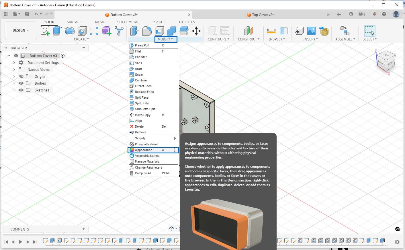
Appearance will control color, texture, surface finish, and render look. Steps to do this are click modify → appearance, appearance library open up, apply appearance browse from categories like paint, plastic, metal, rubber, drag appearance onto part, component, body or face (very useful), for example: black plastic for enclosure, metallic screws, matte finish for PCB housing. Physical Material affects mass & physics, used in simulation, one per body/component whereas Appearance is visual only, used in rendering, can be overridden per face.
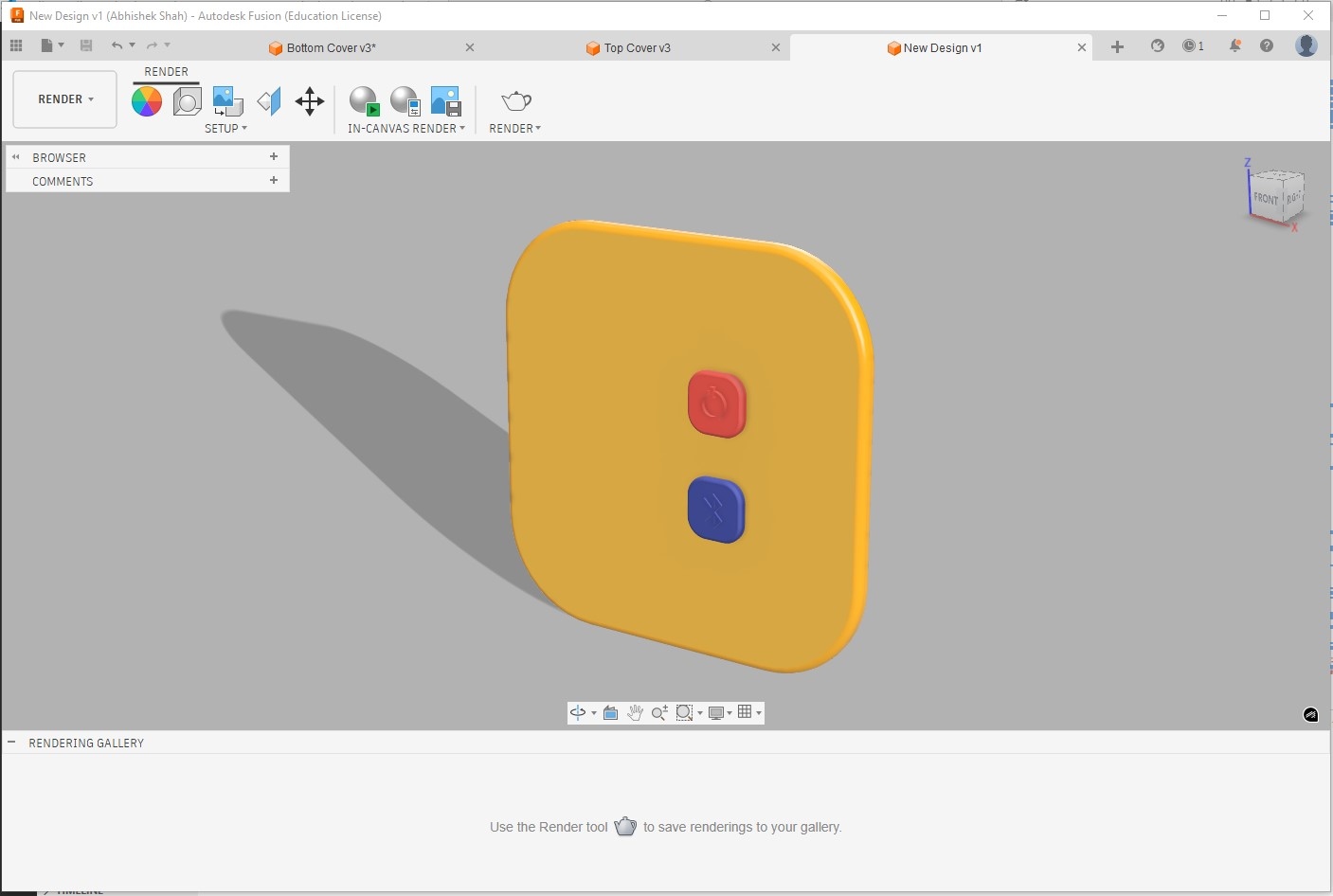
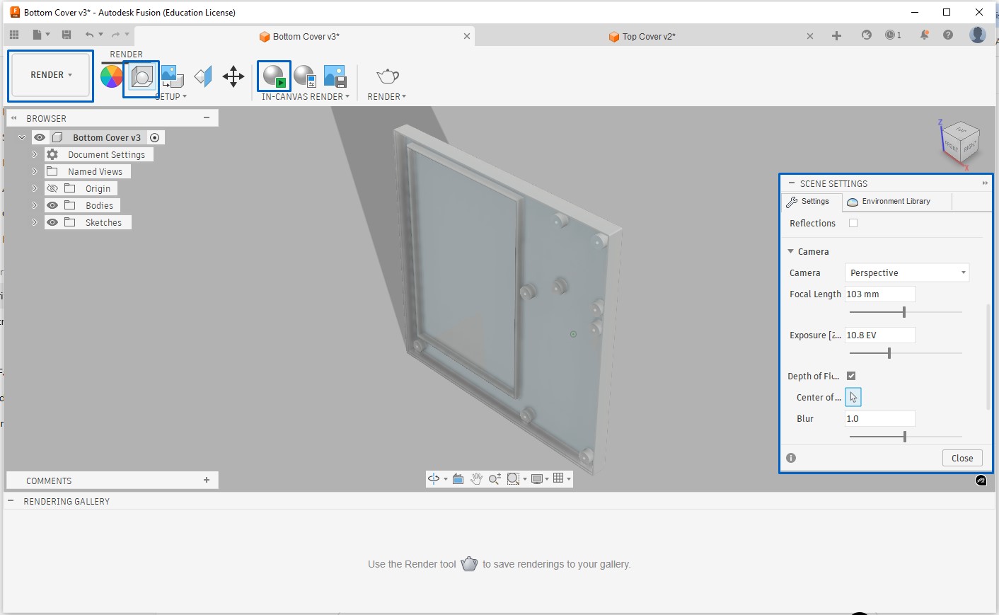
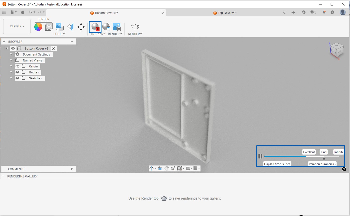
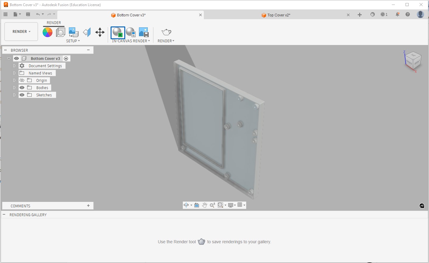
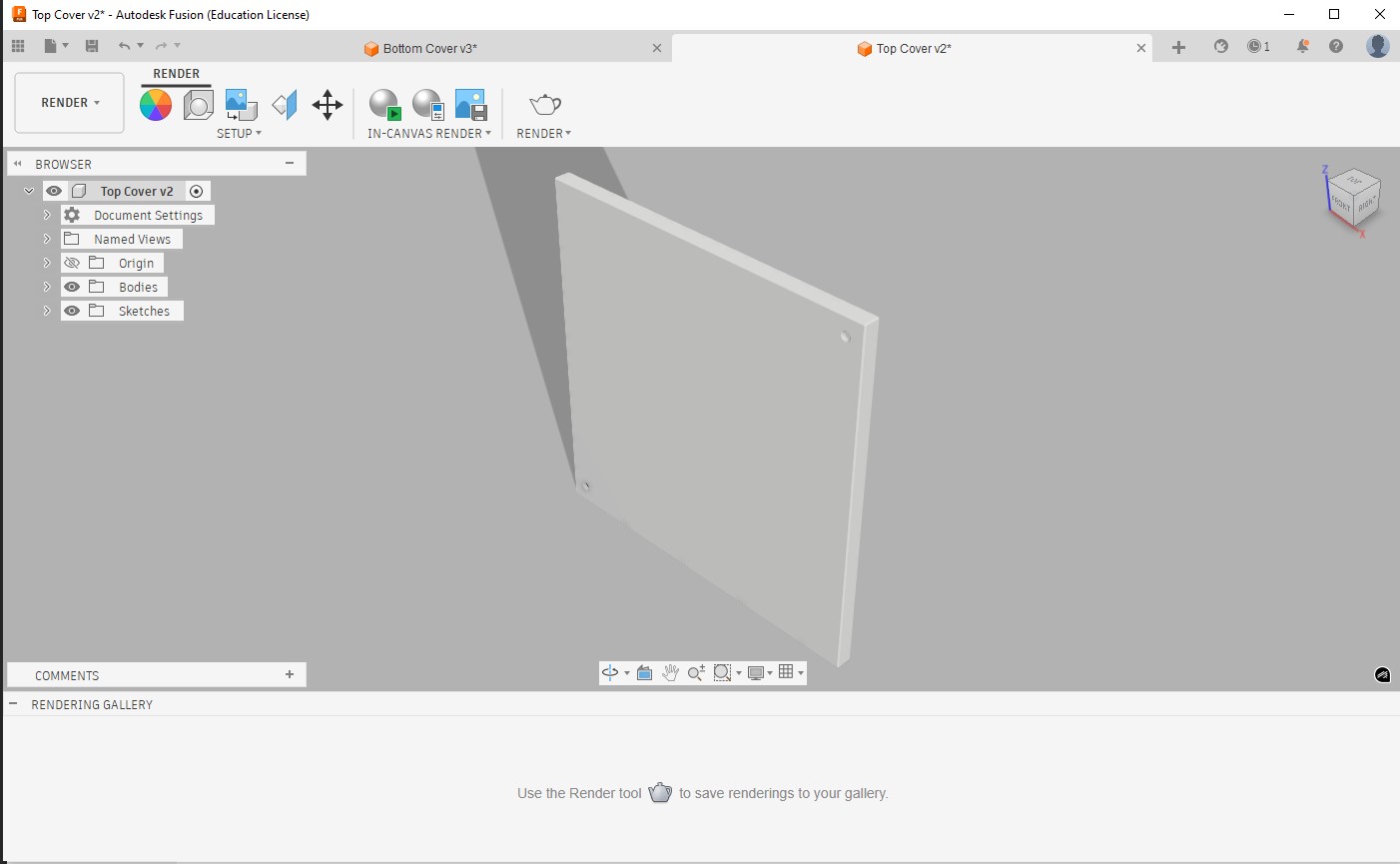
To render the part we need to switch from design to render, under render -> scene settings tab we can adjust lighting, background and shadows. After settings we can start rendering and the part will appear as below, but when rendering process reaches excellent or final level and then we stop rendering process, the part will appear as rendered final part.
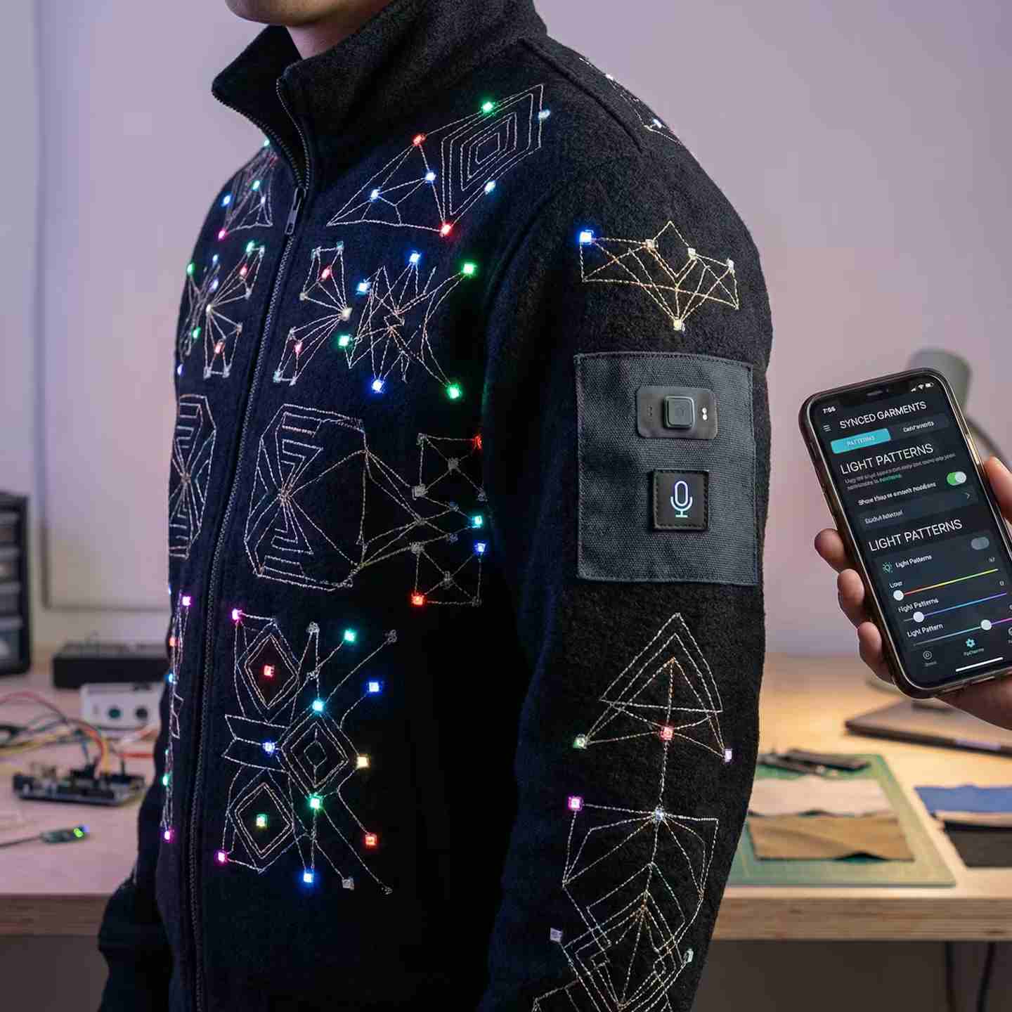
AI-Powered Image Generation
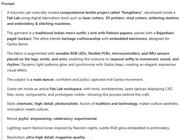
I tried Artlist to generate an AI-rendered visual image, based on below detailed prompt. this time the prompt was not generated by AI(CHatGPT)
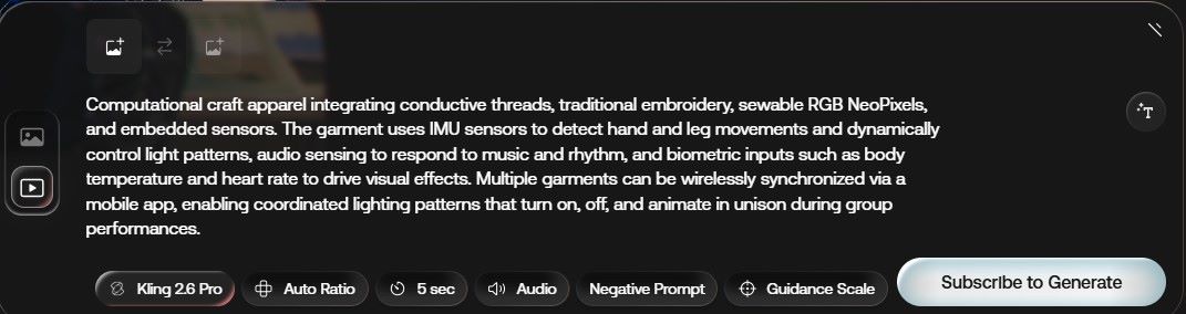
Next, I used CRAIYON to generate an AI-rendered visualization of my project, based on a detailed prompt created with the help of ChatGPT to ensure an accurate and expressive description.
You can try CRAIYON here
I was expecting male image but CRAIYON gave me female image 🙃
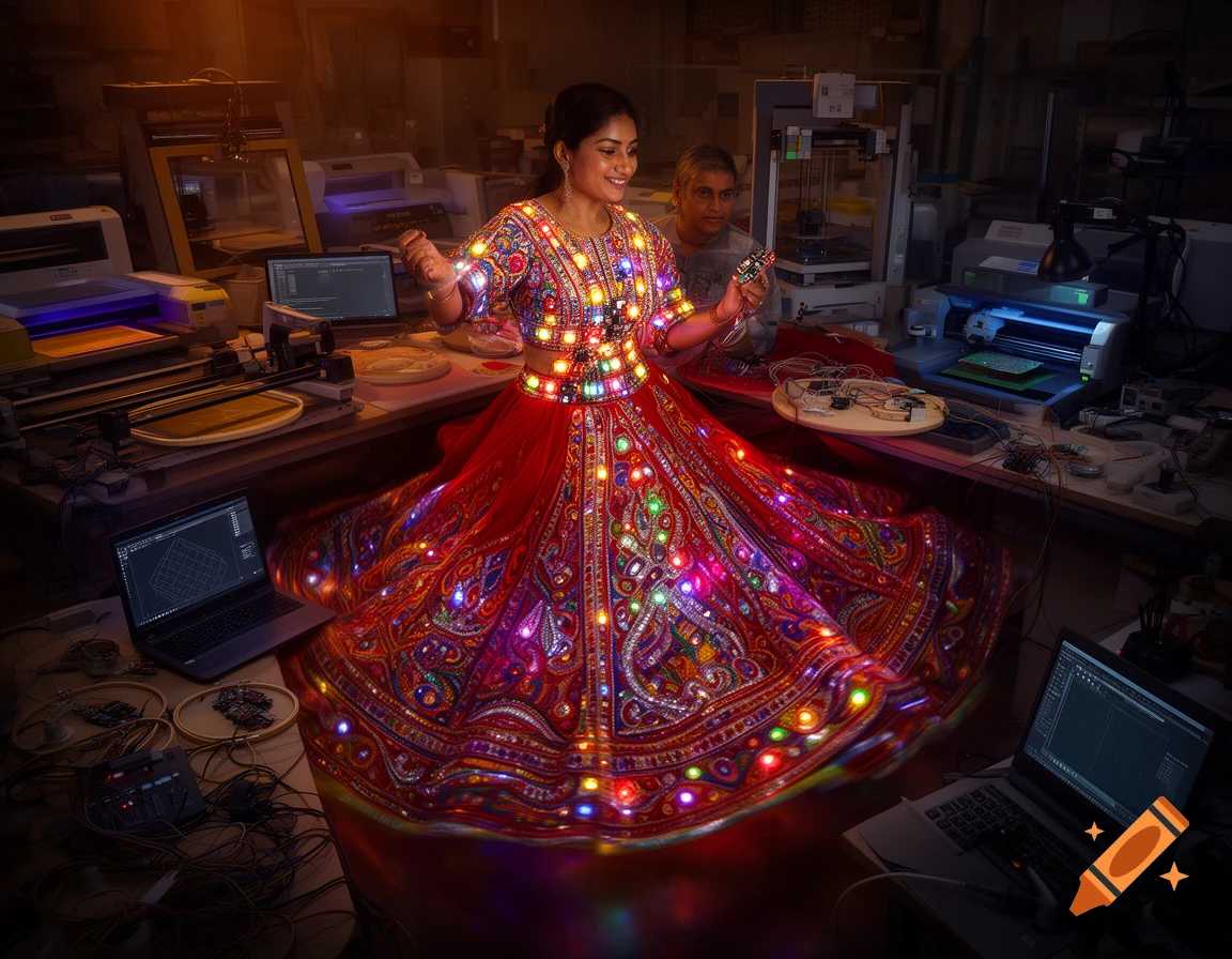
Image resizing Tool
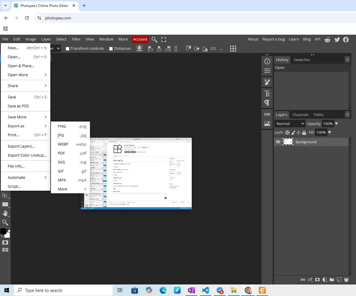
Photopea
Photopea is an online image editing tool used to resize and optimize images without compromising quality.
To improve website performance: PNG images are converted to JPEG, Image sizes are kept below 100 KB, This reduces page load time and memory usage Photopea
Video resizing Tool
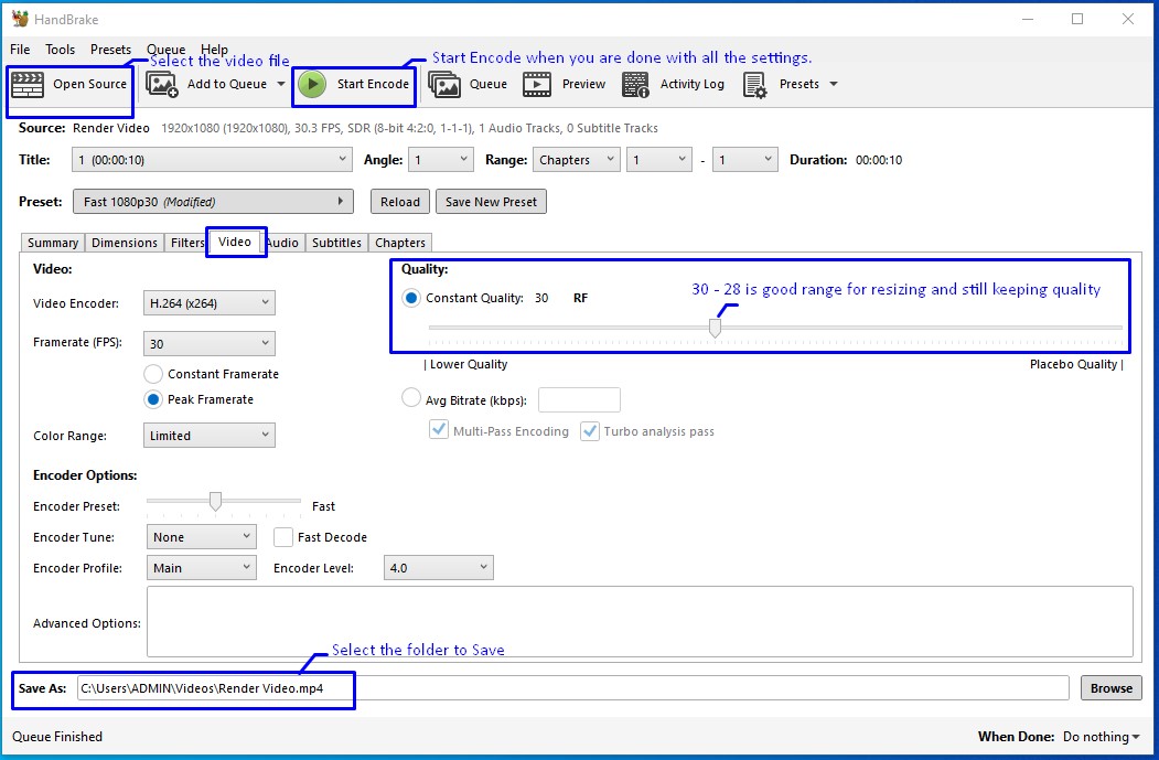
HandBrake
HandBrake is an open-source video transcoder used to compress and convert videos into widely supported formats.
Documentation Tool
Flameshot
We installed Flameshot, a powerful screenshot tool that allows capturing, annotating, and highlighting images—very useful for technical documentation. Flameshot