Week 9 – Input Devices
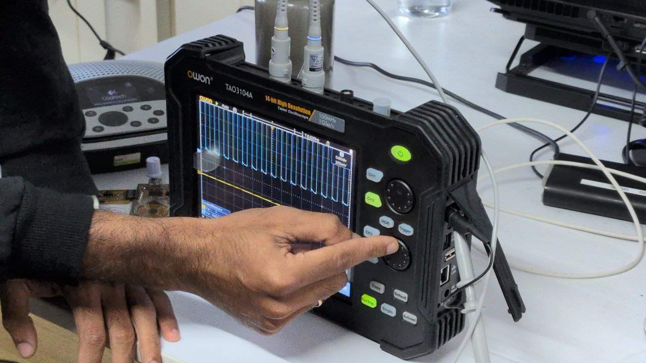
The oscilloscope used was the OWON TAO3104A.
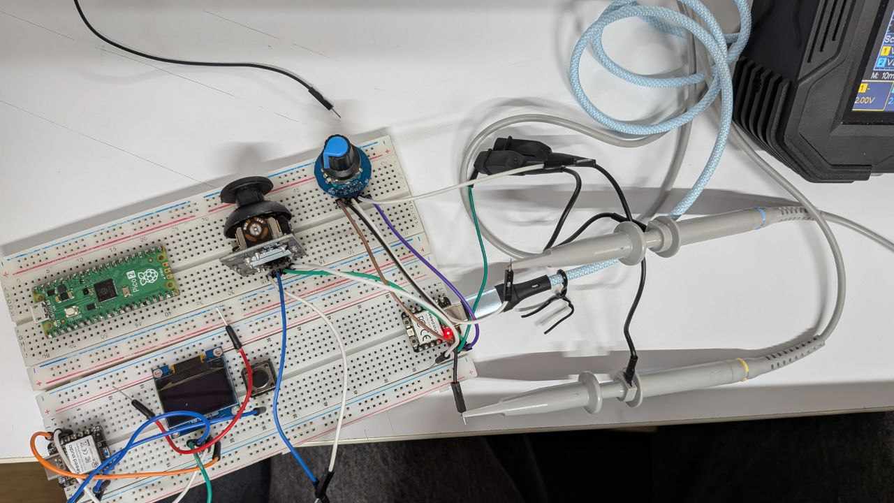
Rotary Encoder
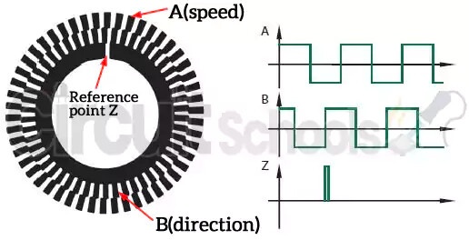
A rotary encoder is an electromechanical device that attaches to a motor or shaft assembly to accurately report the position, speed, and even acceleration of the rotating shaft.
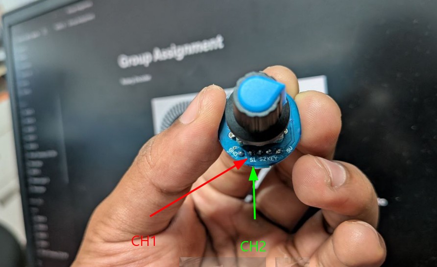
In this setup, the S1 and S2 pinouts are probed using CH1 and CH2 of an oscilloscope, with a common ground provided.
The encoder generates two signals that are offset by 90 degrees, known as quadrature signals. This phase difference allows us to determine the direction of rotation, since one signal will lead or lag the other depending on how the shaft is turned.
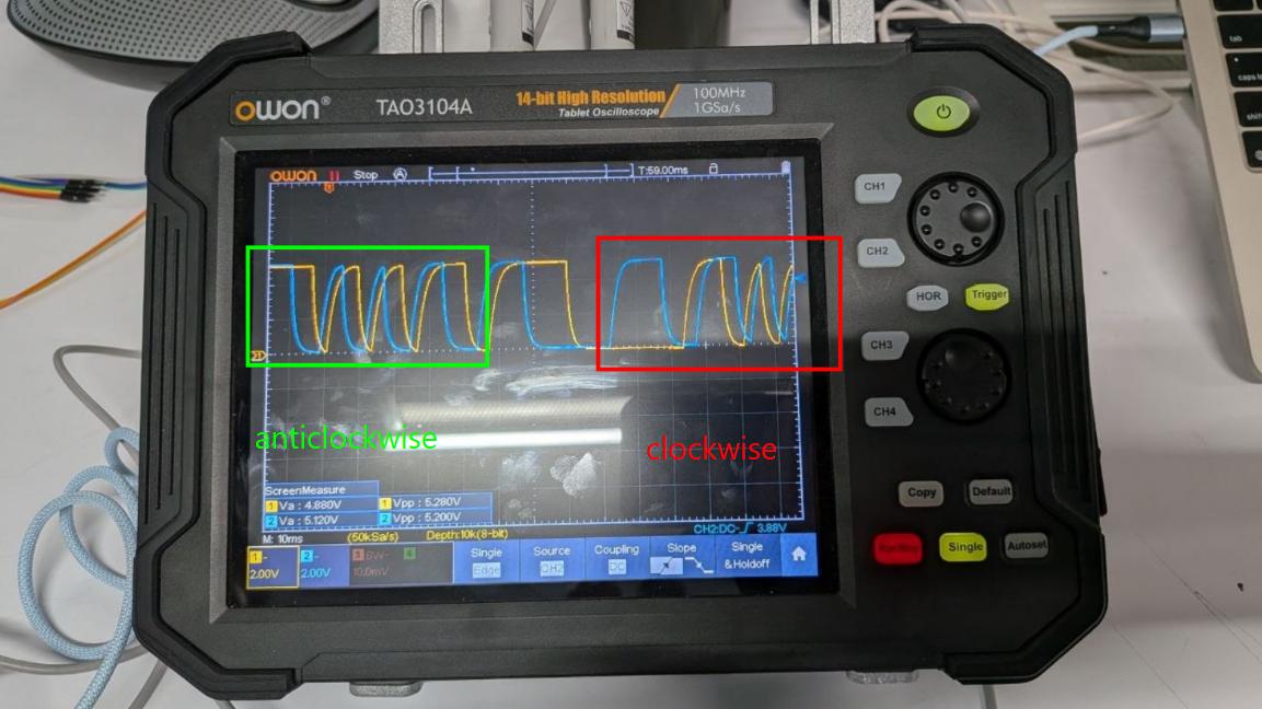
By observing how fast these signals change, we can also determine the rotational speed. Although the waveform may appear somewhat analog due to physical switching characteristics, the encoder effectively produces digital signals that switch between high and low states.
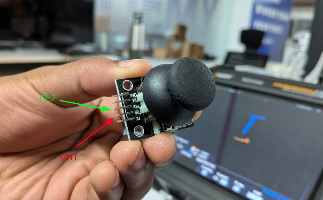
Joystick
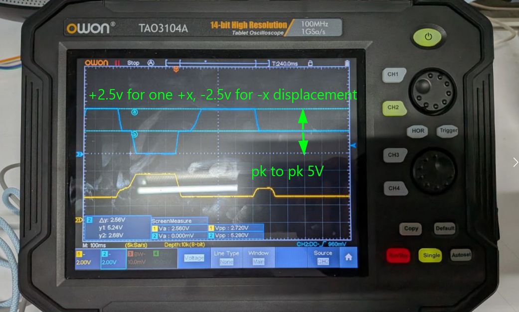
A joystick is an analog input device that typically provides two axes of movement.
In this case, it uses two output pins, VRx and VRy, to represent the horizontal and vertical positions. These are probed to Channel 2 and Channel 1 on the oscilloscope. Common Ground is given as well.
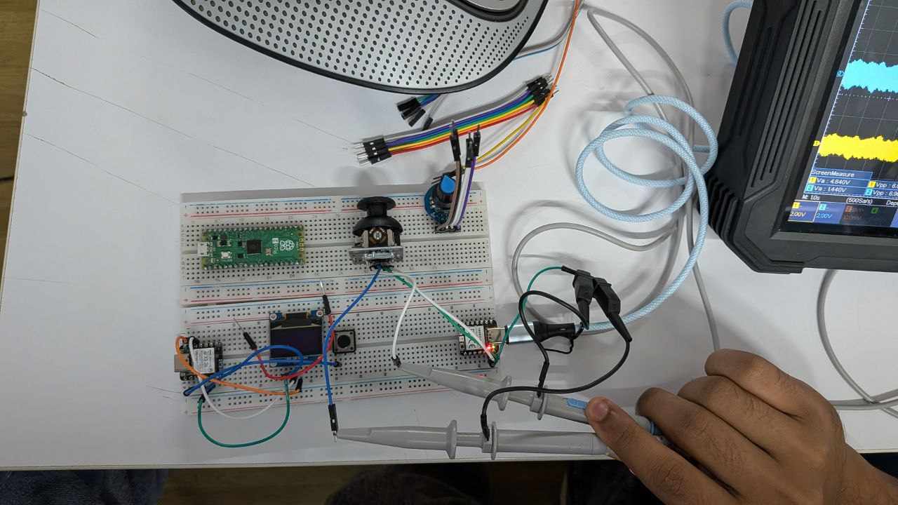
The joystick is powered by a 5 volt supply and internally uses two 5 kilo ohm potentiometers. As the joystick is moved along the x or y direction, the resistance of these potentiometers changes, producing a corresponding voltage between 0 and approximately 5 volts.
These continuous analog signals allow precise measurement of the joystick’s position along both axes.