3D Printing
3D printing, also called additive manufacturing, is a fabrication method where physical objects are produced layer-by-layer from a digital model. Unlike traditional subtractive manufacturing, which removes material from a block, 3D printing builds parts by adding material only where required. This enables the creation of complex geometries, internal cavities, and customized designs that are difficult or impossible to produce with conventional manufacturing techniques. It is widely used in prototyping, product development, education, medical applications, and small-scale production.
Different Types of 3D Printers
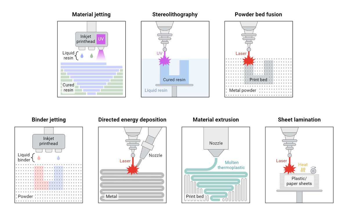
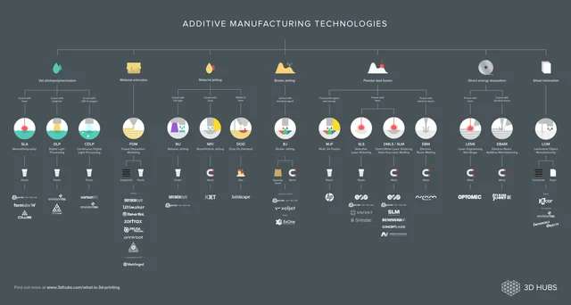
There are multiple 3D printing technologies available today, each working with different materials and suited for different applications.
The most common types include:
1. Fused Deposition Modeling (FDM)
FDM printers create objects by heating thermoplastic filament and extruding it through a nozzle. The material is deposited layer by layer and solidifies as it cools. This is the most widely used type due to its affordability and simplicity.
Advantages: Low cost, easy to operate, good for functional parts
Disadvantages: Visible layer lines, lower surface quality compared to resin printing
2. Stereolithography (SLA)
SLA printers use a laser to cure liquid resin into solid form. The laser traces each layer on the resin surface, and the object gradually forms as layers are stacked
Advantages: Very smooth surface finish, high precision
Disadvantages: Resin handling is messy, requires post-processing
3. Selective Laser Sintering (SLS)
SLS printers use a high-powered laser to fuse powdered materials into solid objects. The powder itself acts as a support, eliminating the need for additional support structures.
Advantages: Strong parts, no supports required, complex geometries possible
Disadvantages: Expensive equipment, rougher surface finish
Applications: Functional prototypes, industrial components
4. Digital Light Processing (DLP)
DLP printing is similar to SLA but uses a digital projector to cure entire layers at once. This enables faster printing than laser-based systems
Advantages: Faster printing speed, good surface finish
Disadvantages: Limited build size, resin handling required
| Printer Type | Technology Used | Energy Source | Materials Used | How It Works | Common Applications |
|---|---|---|---|---|---|
| Fused Deposition Modeling (FDM) | Extrusion-based additive manufacturing | Heat (heated nozzle melts filament) | PLA, ABS, PETG, TPU, Nylon, Composite filaments | A thermoplastic filament is fed into a heated nozzle, where it melts and is deposited layer by layer onto the build platform. The material cools and solidifies to form the object. | Prototyping, functional parts, mechanical components, educational use |
| Stereolithography (SLA) | Vat photopolymerization | UV Laser | Liquid photopolymer resin | A UV laser selectively cures liquid resin layer by layer. The laser traces the shape of each layer on the resin surface, hardening it into solid form. The build platform moves to allow the next layer to be formed. | Dental models, jewelry, high-detail prototypes |
| Digital Light Processing (DLP) | Vat photopolymerization using projected light | UV Light Projector | Photopolymer resin | Instead of tracing with a laser, a projector flashes an entire layer image at once, curing the resin layer instantly. This makes printing faster compared to SLA. | Miniatures, medical models, precision parts |
| Selective Laser Sintering (SLS) | Powder bed fusion | High-power Laser | Nylon, Polyamide, Polymer powders | A laser selectively fuses powdered material layer by layer. After each layer, a new layer of powder is spread over the surface. The surrounding powder supports the structure. | Functional prototypes, industrial components |
| Selective Laser Melting (SLM) | Powder bed fusion | High-power Laser | Metal powders (Stainless steel, Titanium, Aluminum) | Similar to SLS, but the laser fully melts the metal powder instead of just fusing it. This produces strong, dense metal parts. | Aerospace, automotive, medical implants |
| Electron Beam Melting (EBM) | Powder bed fusion | Electron Beam | Metal powders (Titanium, Cobalt-Chrome) | Uses an electron beam in a vacuum to melt metal powder layer by layer. It is faster for metal printing and produces strong parts. | Aerospace, orthopedic implants |
| Binder Jetting | Powder binding process | Liquid Binder (chemical bonding, no heat during printing) | Sand, Metal, Ceramic powders | A liquid binding agent is deposited onto powder layers to bind particles together. After printing, parts are usually sintered to increase strength. | Sand casting molds, metal parts |
| Material Jetting | Inkjet-based additive manufacturing | UV Light | Photopolymer resin | Droplets of liquid resin are sprayed onto the build platform and immediately cured using UV light. This produces smooth and detailed objects. | Medical models, multi-color prototypes |
| Direct Energy Deposition (DED) | Directed material deposition | Laser or Electron Beam | Metal wire or powder | Metal material is melted as it is deposited using focused energy. It is often used to repair or build large metal components. | Aerospace repair, industrial manufacturing |
| Laminated Object Manufacturing (LOM) | Sheet lamination | Heat and Pressure | Paper, Plastic sheets, Metal foil | Layers of material sheets are bonded together using heat and pressure, then cut to shape using a laser or blade. | Concept models, visual prototypes |
the prompt used is :
explain all different types of 3d printer types with the below details and make a table . Details to Add to Each Printer Type: Technology Used: Explain how the printer works, the type of energy used (laser, heat, etc.), and the materials it can process.
source: https://www.biorender.com/template/types-of-additive-manufacturing-in-3d-printing
Each type of 3D printer has its own advantages and limitations in terms of material compatibility, print quality, speed, and cost. The choice of printer depends heavily on the specific application requirements, budget constraints, and desired end product characteristics. Understanding these different technologies is crucial for selecting the right printer for your needs.
source : https://www.reddit.com/r/engineering/comments/4xdnmc/additive_manufacturing_technologies_overview/
Safety Measures While Using a 3D Printer
Read the User Manual – Before operating the printer, carefully go through the user manual and understand the recommended safety instructions and operating procedures.
Ensure Proper Ventilation – Some materials, especially ABS and resin, can release fumes during printing. Always use the printer in a well-ventilated space or with proper air filtration.
Avoid Touching Hot Components – Parts such as the nozzle and heated bed can reach very high temperatures. Allow sufficient time for them to cool down before handling.
Use Personal Protective Equipment (PPE) – When working with resin or during post-processing, wear gloves and safety glasses to protect your skin and eyes.
Supervise the Printer During Operation – Do not leave the printer running unattended for long periods, as this can increase the risk of overheating or fire hazards.
Keep the Area Free from Flammable Materials – Make sure there are no flammable items such as paper, cloth, or liquids near the printer while it is operating.
Use Compatible and Good-Quality Materials – Always use the correct filament or resin recommended for your printer to avoid clogs, print failures, or safety issues.
Handle Resin Carefully – Liquid resin can be harmful if it comes into contact with skin. Use nitrile gloves and avoid direct contact when handling resin.
Dispose of Waste Properly – Failed prints, used resin, and support materials should be discarded according to proper waste disposal and environmental guidelines.
Check Electrical Connections – Ensure the printer is connected safely, preferably using a surge protector, and regularly inspect cables for damage.
Stay Clear of Moving Parts – Do not place your hands or tools near moving components such as belts, motors, and extruders while the printer is running.
Perform Regular Maintenance – Clean the printer and inspect its components regularly to ensure smooth and safe operation.
Use an Enclosure When Necessary – For high-temperature materials, using an enclosure helps contain heat and fumes, improving both safety and print quality.
Take Care During Post-Processing – Activities like sanding, cutting, or using chemicals should be done in a ventilated area while wearing appropriate protective equipment.
Be Prepared for Emergencies – Always keep a fire extinguisher nearby and know how to quickly switch off the printer in case of an emergency.
Design Rules for 3D Printing
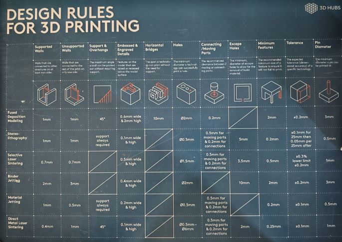
When working with 3D printers, especially FDM machines, knowing how to design parts so that they actually print successfully is crucial. The Fab Academy group assignment asks us to test and understand these rules because every machine has its own strengths and limitations.
Here’s a summary of the key design considerations we learned:
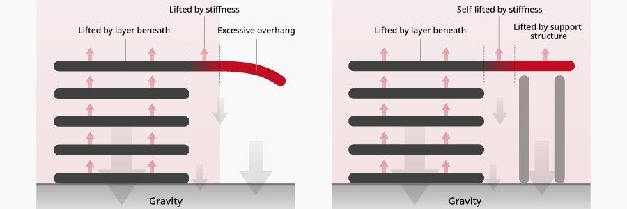
Supports
To build parts with overhanging or unsupported shapes, the printer needs structures under them. These are called supports. They act like temporary scaffolding for material that can’t rest on anything below it.
A support is used to prevent overhanging layers from collapsing.
- Supports are printed from the same material as your part.
- They are usually designed to be removed easily without harming the main model.
- There are different patterns (like lattice or tree supports), each affecting ease of removal and surface finish differently.
 source : https://www.raise3d.com/academy/when-and-how-to-use-3d-printed-support-structures/
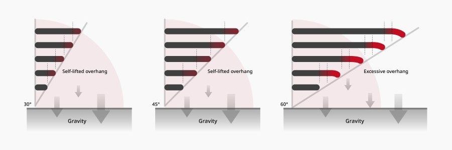
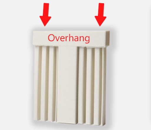
Overhangs
An overhang is a part of the print that extends outward without direct support below it. Overhangs are surfaces printed at an angle without support underneath. Most FDM printers handle angles up to 45° reliably.
Typical safe overhang angle ≈ 45°
- Small overhangs (generally under about 45° tilt) often print cleanly without support.
- Steeper or larger overhangs typically require supports, or they may droop or distort.
 source : https://www.raise3d.com/academy/when-and-how-to-use-3d-printed-support-structures/
 source : https://my.cytron.io/tutorial/what-are-supports-in-3d-printing
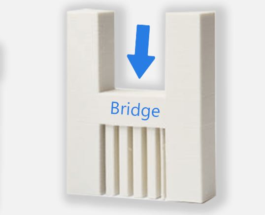
Bridging
A bridge is similar to an overhang but has two supported ends with empty space in between — like a small span between walls.Bridging occurs when material spans between two supported edges. Short bridges print well, long bridges may sag.
- Short bridges (e.g., under ~5 mm) can often print fine without supports.
- Longer bridges tend to sag and need either support or careful slicer tuning.
 source : https://my.cytron.io/tutorial/what-are-supports-in-3d-printing
Wall Thickness
Wall thickness must be greater than the nozzle diameter for reliable extrusion. The printer nozzle and extrusion width determine how thin your walls can be:
- Very thin walls may not print reliably or could be fragile.
- A good rule is to make walls at least slightly thicker than your nozzle diameter so the printer can trace them properly.
Minimum wall thickness ≥ Nozzle diameter × 1.2
 source : http://unionfab.com/blog/2024/09/3d-printing-wall-thickness
Dimensional Accuracy
The difference between your CAD design and the real printed part is influenced by:
- print temperatures
- material shrinkage
- mechanical precision of the printer
For functional parts, you often need to account for this by adjusting dimensions or adding clearance.
Clearance & Tolerance
For moving parts, clearance between components is critical.
Clearance = Dhole − Dshaft
- 0.2 mm → Often fused
- 0.3 mm → Tight fit
- 0.4–0.5 mm → Safer rotation
Infill
Infill determines internal strength and material usage. Inside your printed parts, the infill determines strength, weight, and material usage, common patterns include: Line, Grid, Triangular, Gyroid. Each pattern has different trade-offs between rigidity and print time. For many functional parts, 10–20 % infill offers a good balance.
- 10–20% → Light functional parts
- 30–50% → Structural strength
- Gyroid → Balanced strength distribution
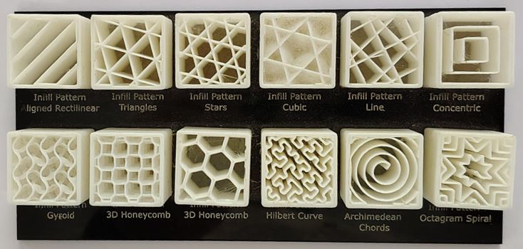
| Infill Pattern | Description | Strength | Print Speed |
|---|---|---|---|
| Line | Alternating parallel lines printed layer by layer. | Moderate | Fast |
| Grid | Crisscross lines intersecting at 90° angles. | Moderate to Strong | Fast |
| Triangular | Intersecting lines forming 60° triangles. | Strong | Medium |
| Tri-Hexagon | Hexagon pattern reinforced with triangles. | Very Strong | Medium |
| Cubic | Stacked offset cubic cells forming a 3D lattice. | Strong | Medium |
| Honeycomb | Hexagonal cells similar to a beehive. | Strong (high strength-to-weight ratio) | Medium |
| Gyroid | Continuous wavy 3D structure with balanced strength in all directions. | Strong & Isotropic | Medium |
| Concentric | Follows the model’s outer shape inward in loops. | Low to Moderate | Very Fast |
| Lightning | Internal support added only where necessary. | Low (material saving) | Fastest |
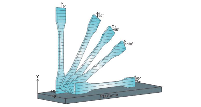
Anisotropy
FDM parts are weaker in the vertical (Z) direction due to layer bonding. Orientation directly affects strength. 3D prints are strongest along the direction of the layers they are built in. Because material is laid down one layer at a time:
- Parts may be weaker in the vertical (Z) direction compared to horizontal.
- This is called anisotropic behavior — meaning mechanical properties depend on orientation.
 source : https://www.sciencedirect.com/science/article/abs/pii/S1359836816309052
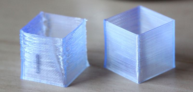
Surface Finish
Surface finish refers to the visible layer lines and texture on a printed part:
- Smooth curves and slanted surfaces show more layer lines.
- Higher layer resolution (smaller layer height) improves appearance but increases print time.
Why These Rules Matter
Understanding these design rules helps you predict whether a part will succeed or fail before printing it. These rules help you design for:
- Printability
- Structural performance
- Efficient use of material and time
BAMBU LAB A1
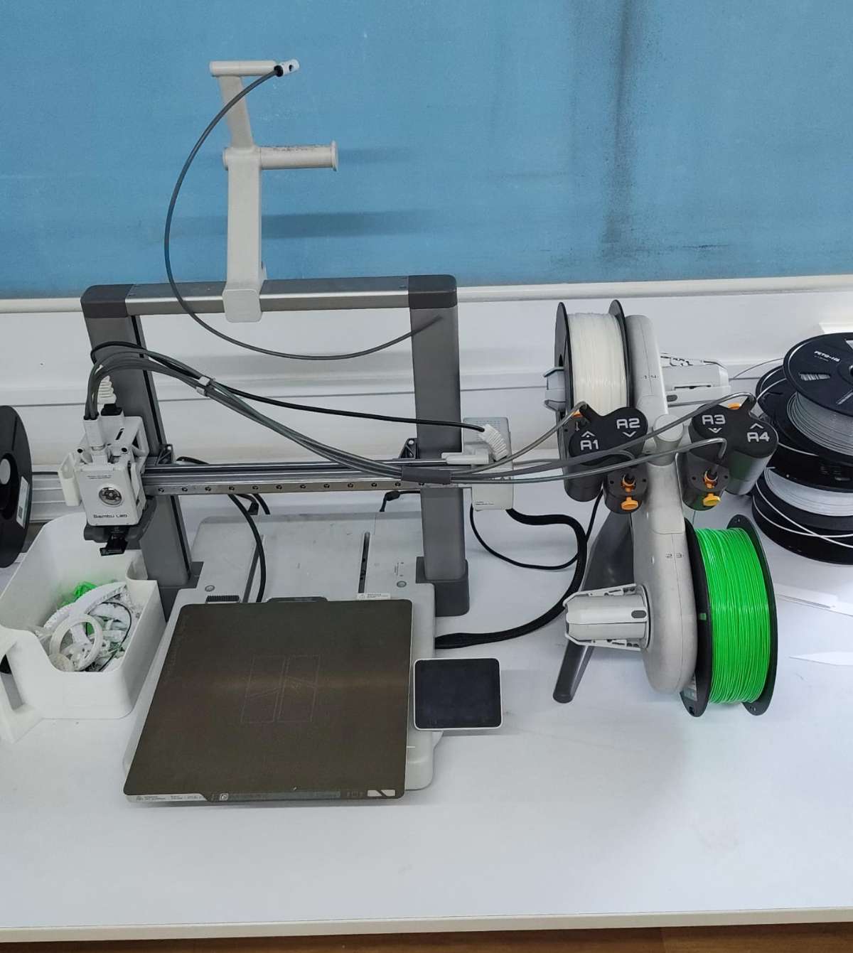
The Bambu Lab A1 is an advanced desktop FDM 3D printer designed to deliver high speed, precision, and automation. It is suitable for both beginners and experienced users due to its intelligent calibration features and easy-to-use interface. The printer uses a modern motion system and built-in sensors to automatically adjust printing parameters, improving reliability and print quality.
Key Features of Bambu Lab A1
- Automatic Z-Offset Calibration: The printer automatically measures and adjusts the nozzle distance from the build plate, eliminating the need for manual leveling.
- Automatic Flow Calibration: The printer adjusts extrusion settings automatically to ensure proper filament flow and improve print quality.
- Vibration Compensation System: Built-in sensors detect vibration and adjust motion settings to reduce defects and improve surface finish.
- Automatic Belt Adjustment: The printer monitors belt tension and maintains optimal performance without manual tuning.
- Automatic Filament Handling: Filament loading and unloading can be done easily using the printer interface.
- Multi-Color Printing Support: When connected to AMS Lite, the printer can print using multiple filament colors in a single print.
- Real-Time Extrusion Monitoring: Sensors monitor extrusion behavior to maintain consistent printing performance.
- Noise Reduction System: The printer uses optimized motor control to minimize operational noise.
- High-Speed Printing Capability: Designed to print faster while maintaining dimensional accuracy and stability.
- User-Friendly Interface: Equipped with a touchscreen display for easy control and monitoring.
- Offline Printing Capability: Supports local operation without requiring internet connectivity.
Technical Specifications of Bambu Lab A1
| Specification | Details |
|---|---|
| Build Volume | 256 × 256 × 256 mm |
| Printing Technology | Fused Deposition Modeling (FDM) |
| Motion System | Core XY motion system |
| Filament Diameter | 1.75 mm |
| Nozzle Diameter | 0.4 mm (standard), optional sizes available |
| Maximum Nozzle Temperature | 300°C |
| Maximum Bed Temperature | 100°C |
| Supported Materials | PLA, PETG, TPU, ABS, ASA, Nylon, and others |
| Layer Height Range | 0.08 mm to 0.28 mm |
| Maximum Print Speed | Up to 500 mm/s |
| Build Plate Type | PEI spring steel plate |
| Sensors | Filament run-out sensor, extrusion monitoring sensor |
| Recovery Feature | Supports resume printing after power loss |
Source : https://gzhls.at/blob/ldb/8/b/9/6/e11ab07c47dfb806a34940bbfce2b6cf2fe6.pdf
These specifications make the printer suitable for both rapid prototyping and functional part production.
Types of Build Plates
The build plate plays an important role in print adhesion and surface finish. Different types of plates are available depending on material and application requirements.
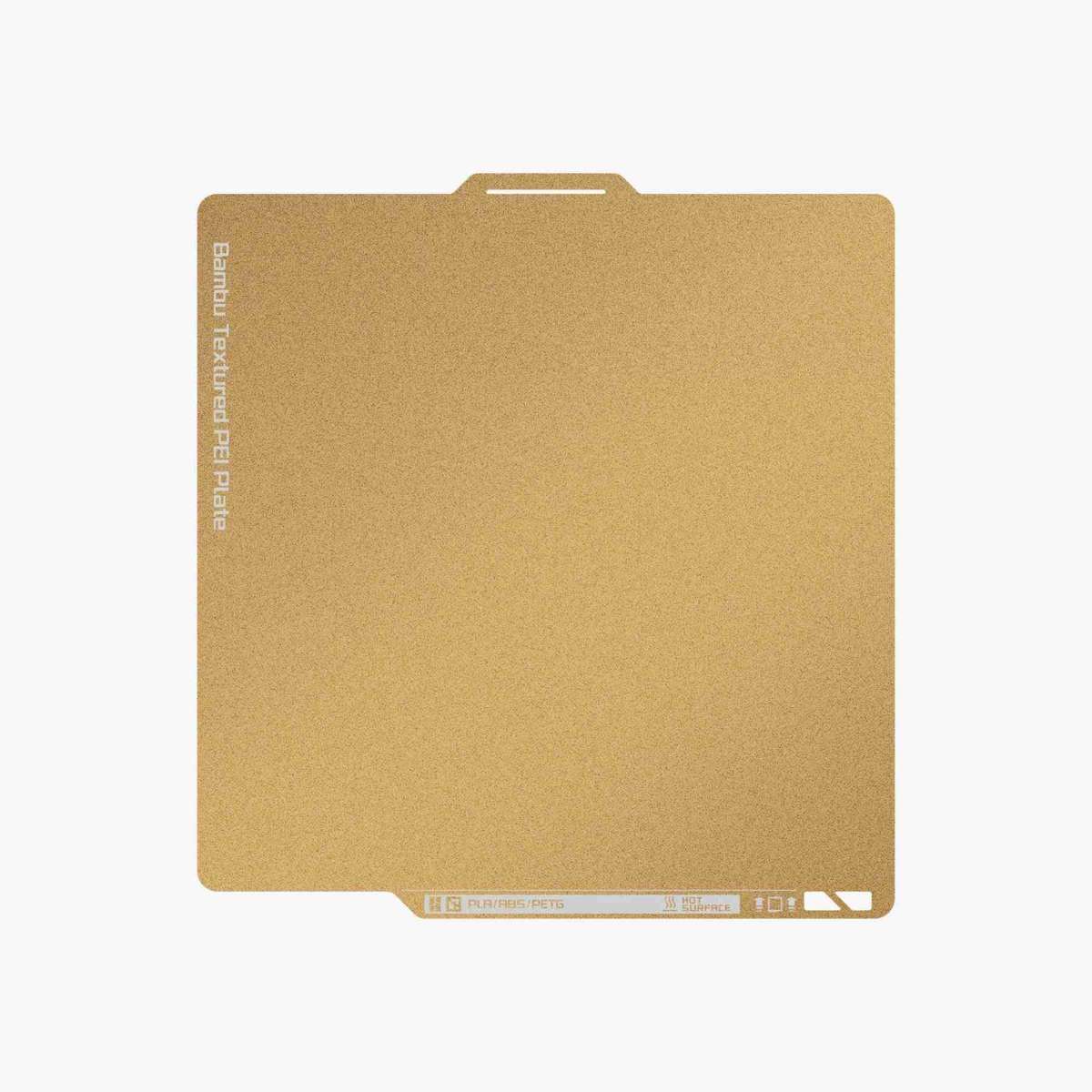
Textured PEI Plate
The textured PEI plate has a rough surface that helps printed parts stick firmly during printing. This texture is transferred slightly onto the bottom surface of the printed object, giving it a matte finish.
This plate works well with most common filaments and usually does not require glue or additional adhesives. It also helps reduce warping and improves print reliability.
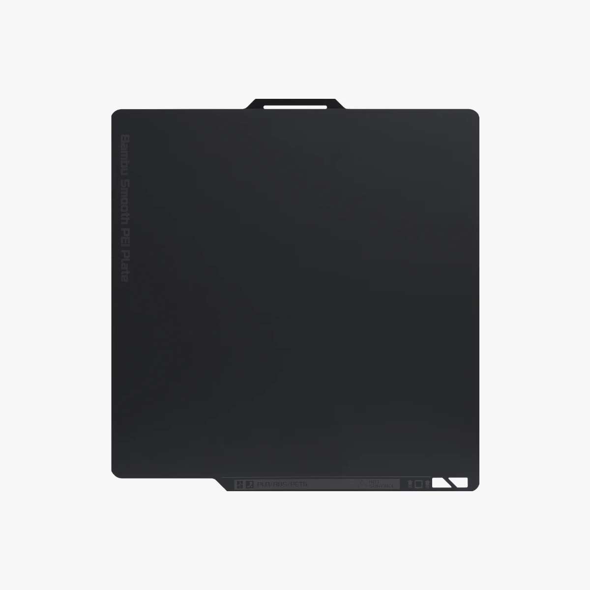
Smooth PEI Plate
The smooth PEI plate provides a flat and even printing surface. It produces prints with a clean and smooth bottom finish, making it suitable for parts that require a better surface appearance.
This plate supports many filament types, but some materials may require glue or adhesive to improve adhesion and prevent damage to the surface.
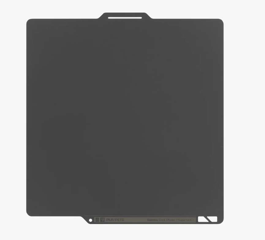
Cool Plate Super Tack
The Cool Plate is designed to provide strong adhesion at lower temperatures. It is especially useful when printing PLA and PETG, as it helps prevent warping while reducing energy consumption.
This plate improves print stability and can increase the lifespan of the build surface due to reduced thermal stress.
Dual-Texture PEI Plate
This plate combines both textured and smooth surfaces on opposite sides. One side provides strong adhesion with a textured finish, while the other side offers a smooth printing surface.
This allows users to choose the surface depending on their print requirements.
Source : https://wiki.bambulab.com/en/filament-acc/acc/plates
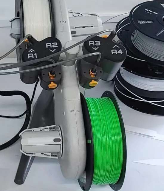
Loading Process
Loading filament into the printer is a simple process and can be done using the printer interface.
Step 1: Prepare the Filament
Place the filament spool on the spool holder and ensure it can rotate freely.
Step 2: Insert the Filament
Insert the filament into the filament entry path until it reaches the extruder.
Step 3: Select Load Option
Using the touchscreen interface, select the option to load filament and choose the correct material type.
Step 4: Nozzle Heating and Extrusion
The printer will heat the nozzle to the required temperature and extrude a small amount of filament to confirm proper loading.
This ensures that the filament is correctly inserted and ready for printing.
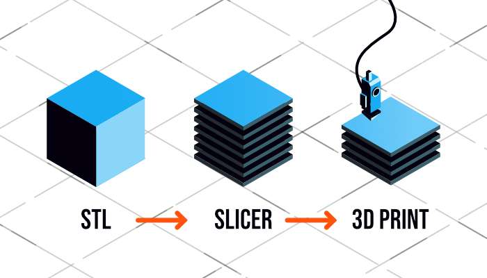
Printer Slicer
A slicer is software used to convert a 3D model into instructions that the printer can understand. The slicer divides the model into multiple thin layers and generates commands for each layer.
Following are the three major types of settings that can be controlled in a slicer software —
- Print Settings: layer heights, shells, infill per cent, and speed
- Filament Settings: filament diameter, extrusion multiplier, the temperature of the extruder, and print bed.
- Printer settings: nozzle diameter, print bed shape (L x W), and Z offset.
The slicer also provides a preview of the print, estimated print time, and material usage.
Bambu Studio is commonly used for the Bambu Lab A1 and provides optimized settings for fast and reliable printing.
G-Code
G-code is the programming language used by 3D printers to perform printing operations. It contains instructions that control printer movements, extrusion amount, and temperature settings.
The slicer software generates G-code automatically from the 3D model. Once transferred to the printer, the printer reads the instructions and prints the object layer by layer.
Each command in the G-code controls specific actions such as:
- Moving the nozzle to a specific position
- Controlling extrusion
- Setting temperatures
- Controlling print speed
This ensures accurate and automated printing.
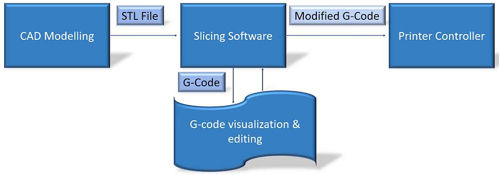
Flow of 3D print :
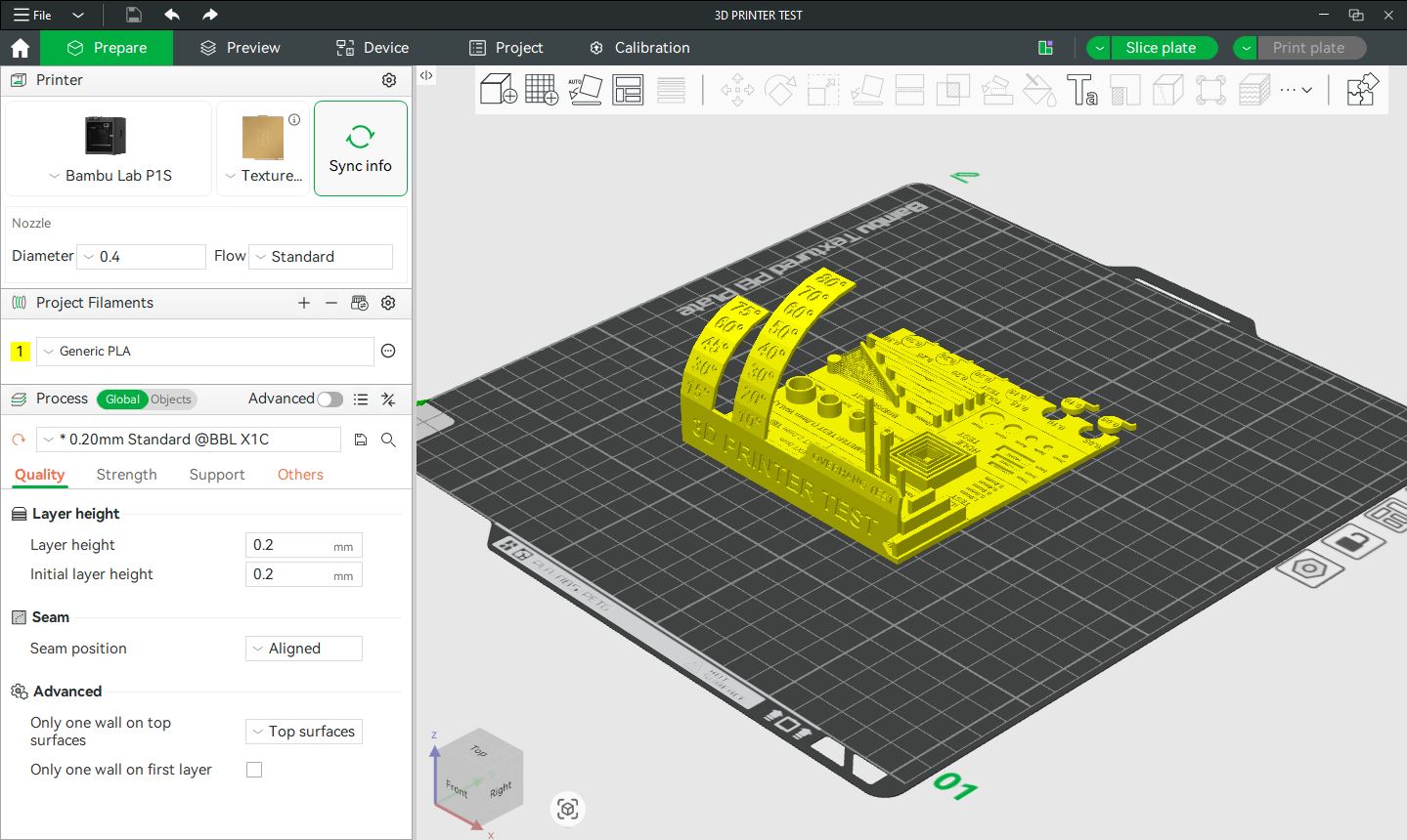
Bambu Studio
Bambu Studio is a slicing software developed by Bambu Lab that is used to prepare 3D models for printing. It converts a 3D model into machine instructions (G-code) that the printer can follow to create the object layer by layer.
It is an open-source, feature-rich software designed specifically for Bambu Lab printers, but it also supports other compatible printers. The software uses optimized slicing algorithms and a project-based workflow to ensure efficient and accurate printing.
Bambu Studio allows users to import 3D files such as STL, OBJ, STEP, and 3MF. The model can be moved, rotated, scaled, and positioned on the virtual build plate before printing.
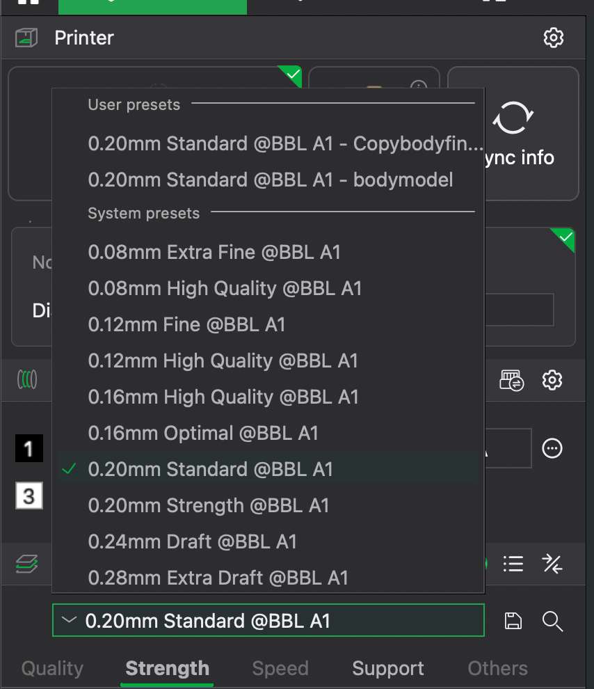
Preset profiles are available for different layer heights, allowing the user to balance print quality and printing time. One of the most commonly used presets is the 0.20 mm Standard setting, which provides a good balance between speed and quality. Lower layer heights produce finer details and smoother surfaces, but they also increase the printing time and material usage.
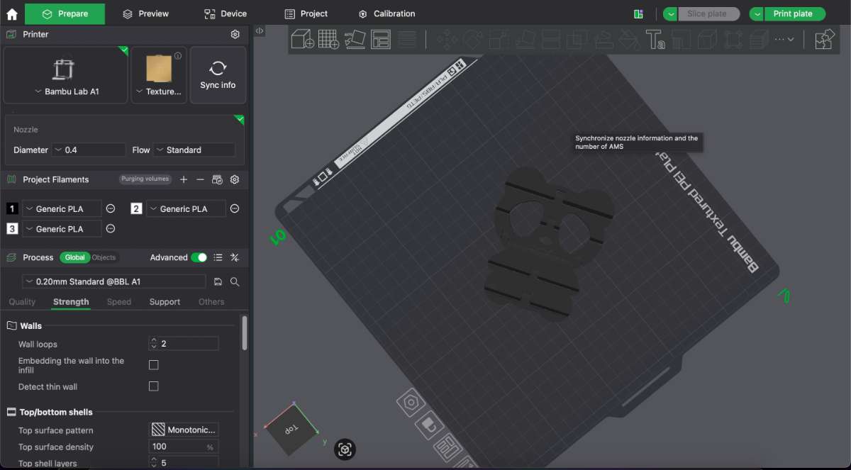
There are mainly 4 Tabs in the Bambu Studio for slicing parameters.
The Quality section controls settings that affect the visual appearance and resolution of the printed object. These settings determine how smooth the surface is and how detailed the final print will be.
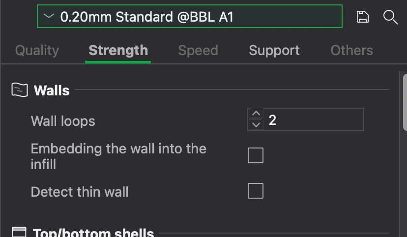
The Strength section controls settings that affect the mechanical strength and durability of the printed part. These settings define how solid the object is internally and externally.
The Strength section controls settings that affect the mechanical strength and durability of the printed part. These settings define how solid the object is internally and externally.
The Others section contains additional advanced settings that affect special print behaviors and overall printing performance.

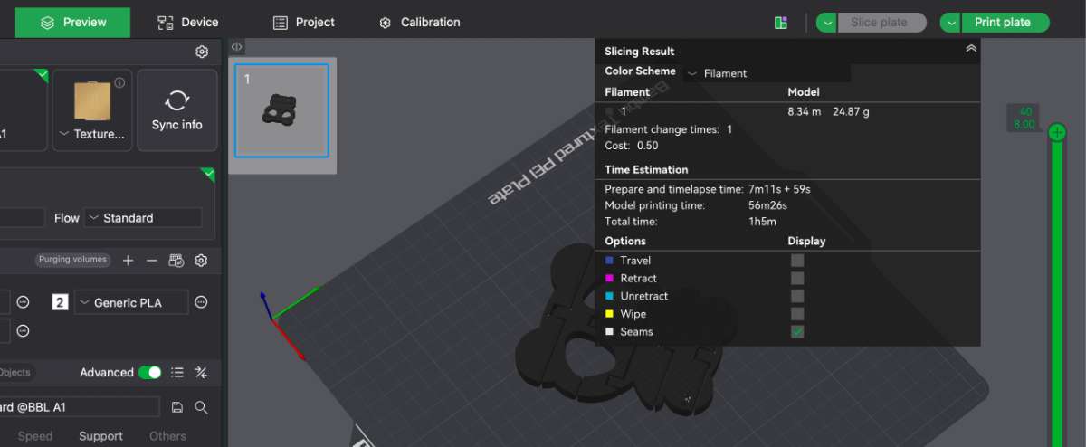
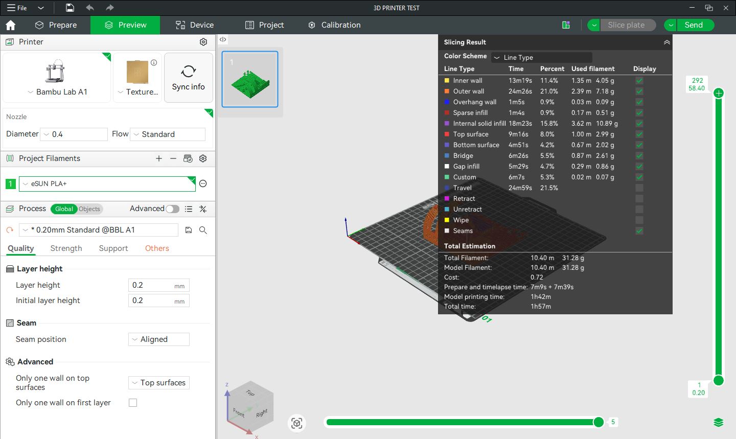
Slicing the Model
The software divides the 3D model into thin layers and generates the toolpath that the printer will follow. This slicing process converts the design into G-code instructions. To slice the object, you go to the “slice plate” on the top toolbar.
Print Settings Configuration
Users can adjust important printing parameters such as:
- Layer height
- Print speed
- Infill density
- Nozzle temperature
- Bed temperature
- Support structures
These settings help control print quality, strength, and printing time.
Preview Function
After slicing, Bambu Studio provides a preview of the print. This shows how each layer will be printed and helps detect possible issues before printing.
Bambu Studio supports multi-color printing using the Automatic Material System (AMS). Users can assign different colors or materials to different parts of the model.
The software allows users to send files directly to the printer and monitor the printing process, including temperature, progress, and filament usage.
source : https://manual.eg.poly.edu/index.php/Bambu_Studio_Guide?utm_source=chatgpt.com

Design Rules for 3D Printing
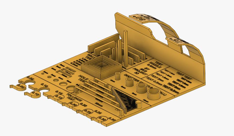
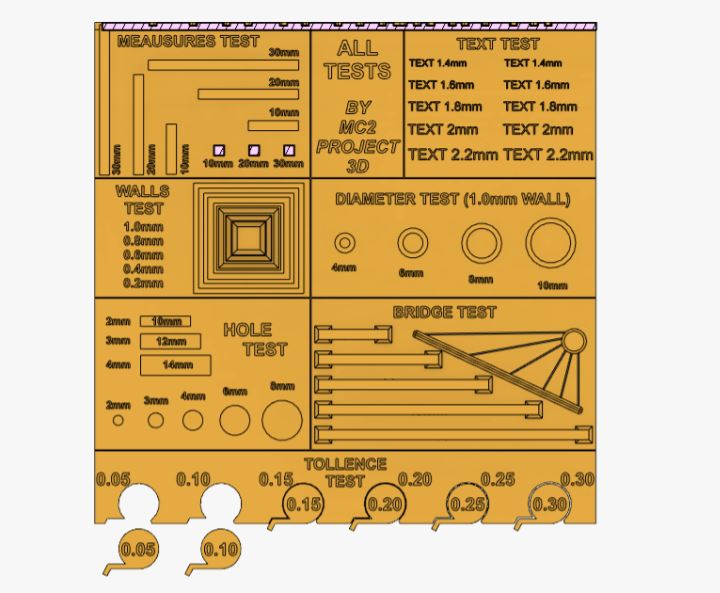
A 3D printer test print is a standardized calibration model used to evaluate machine performance,dimensional accuracy, and process stability. It helps identify common printing defects such as poor bed adhesion, stringing, layer shifting, over-extrusion, under-extrusion, and incorrect temperature settings. Widely used calibration models include the Benchy, which assesses overall print quality and surface finish, and the Calibration Cube, which verifies dimensional accuracy along the X, Y, and Z axes. A Temperature Tower is used to determine the optimal extrusion temperature for a specific filament, while a Retraction Test evaluates stringing behavior. Overhang and Bridging tests measure the printer’s ability to handle unsupported angles and span gaps without sagging. For our evaluation, we used a comprehensive all-in-one calibration model from Thingiverse that integrates multiple performance tests into a single print, enabling efficient validation of printer settings and mechanical accuracy.
We imported the file as STL and imported it into the slicing software then I gave all the parameter and I moved it for printing.
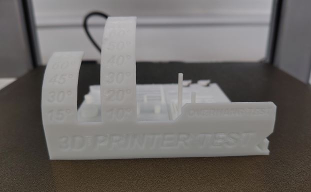
This is the final output.
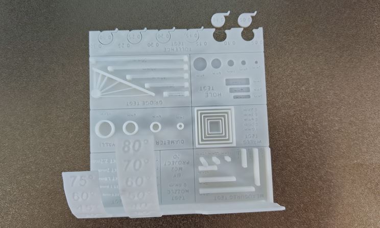
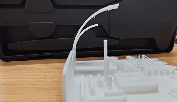
1. Bridge Test
The Bridge Test checks the printer’s ability to print unsupported horizontal spans. A structure with increasing unsupported distances is printed to see if the printer can bridge gaps without excessive sagging or stringing. Poor bridging indicates issues with cooling, over-extrusion, or print speed.
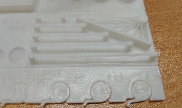
From our observation the 25 mm long bridge started sagging so in design bridge up to 20 mm can be easily printed.
2. Hole Test
The Hole Test checks if circular holes print accurately. A test print with multiple hole sizes is measured, and if the holes are too small, it may indicate over-extrusion or incorrect flow rate settings.
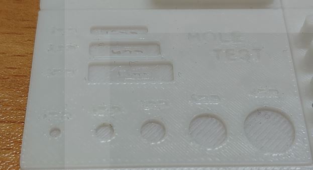
For the hole test from the given dimension 0.4 mm reduction is there this may be due to printer issue or due to the nozzle size.
3. Measurement test
The Measurement Test ensures dimensional accuracy in the X, Y, and Z axes. A cube or rectangular block with known dimensions is printed and measured. Deviations suggest issues like improper steps/mm calibration, belt tension problems, or incorrect flow rate.
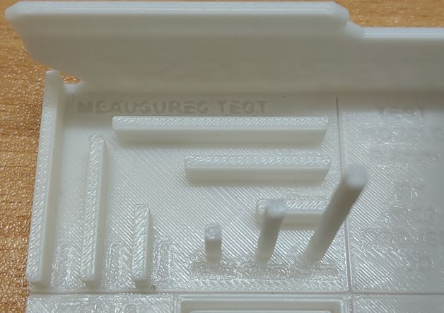
The scaling was pretty precise in this test all the cube had a the same dimension in all orientation.
4.Diameter Test
The Diameter Test ensures cylindrical objects print with the correct diameter. A model with different cylindrical sections is printed and measured. Differences between expected and actual dimensions may indicate extrusion multiplier errors, steps/mm calibration issues, or mechanical inaccuracies.
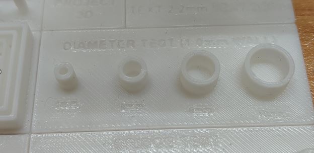
Here for the cylinder’s the actual diameter was 6mm and 8mm but after printing and measuring the dimensions were 5.74 mm and 7.75 mm respectively.
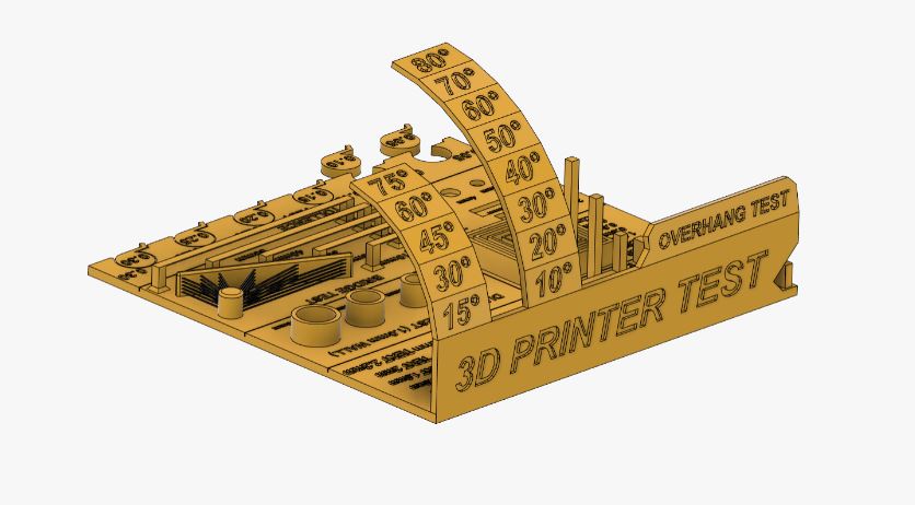
5. Overhang Test
The Overhang Test evaluates how well the printer handles overhangs at different angles without supports. A model with increasing overhang angles (e.g., 10°, 20°, 30°, up to 80°) is printed. Poor performance can indicate insufficient cooling, high print speed, or weak layer adhesion.
From the results obtained errors start to appear after 45 deg
6.Clearance Test
This is a simple test print made for finding the tolerance of a printer the findings from this printer can be implemented in the designs.
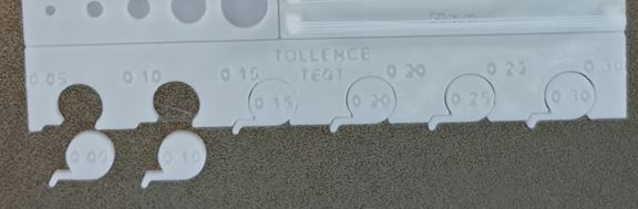
From out test we identified that tolerance of 0.30mm is too loose, where as 0.05mm and 0.10mm are very tight, 0.15mm can move with good grip, 0.20mm and 0.25mm are good enough for free rotation.
Conclusion
For our group assignment, we conducted a test print using the Bambu Lab A1 printer. An all-in-one calibration model was downloaded from Thingiverse and printed to evaluate the machine’s performance. After printing, we carefully measured the model and recorded the observed values, which will serve as reference data for future design work.
Through this process, we gained practical understanding of design rules for 3D printing, important ,safety precautions, and the different types of additive manufacturing technologies. We also discussed the technical specifications and key features of the printer to better understand its capabilities and limitations.
Pre-Print Checklist
- Is the model oriented for maximum strength?
- Are overhangs within 45° or supported?
- Are bridges within acceptable span length?
- Is wall thickness greater than nozzle diameter?
- Have I added sufficient clearance for moving parts?
- Is infill appropriate for strength requirement?
- Is the correct material selected?
- Bed cleaned and leveled?
- Correct temperature settings applied?
- Supports optimized for easy removal?
Reminder: Always preview layer view in slicer before printing.
References
- https://www.hubs.com/knowledge-base/how-design-parts-fdm-3d-printing/#overhangs
- https://www.hubs.com/knowledge-base/supports-3d-printing-technology-overview/
- https://www.cytron.io/tutorial/what-are-supports-in-3d-printing
- https://www.raise3d.com/academy/when-and-how-to-use-3d-printed-support-structures/
- https://all3dp.com/1/3d-printing-support-structures/#section-minimize-3d-printing-support-structures-by-reorientation
- https://dddrop.com/how-to-perfectly-print-a-thin-walled-3d-print/
- https://formlabs.com/asia/blog/isotropy-in-SLA-3D-printing/?srsltid=AfmBOooav7WNQmhJTYYD_RfVHFQ8U7dmDbPvLb_417Kmx2OfYLdSBMKP
- https://www.sciencedirect.com/science/article/abs/pii/S1359836816309052
- https://www.baysingersadditivemanufacturing.com/layer-lines/
- https://3dinsider.com/fix-misaligned-layers-3d-printing/
- https://www.xometry.com/resources/3d-printing/what-is-infill-in-3d-printing/
- https://blog.prusa3d.com/everything-you-need-to-know-about-infills_43579/