INTRODUCTION
This week we're focused on programming embedded systems. What is an embedded system, you may ask? Unlike "traditional" programming which has makers writing and compiling code on more complex and complete operating systems, embedded programming tasks its programmers with writing instructions directly to specialized devices, called microcontrollers, which are essentially the most stripped down bare-bone versions of computers. These tiny devices are controlled in real time, one instruction at a time, and allow users to directly manipulate the flow of current in and out of the device. You can read about our group assignment at Fab Lab ESAN here.
[x] Demonstrate and compare the toolchains and development workflows for available embedded architectures
[x] Document your work to the group work page and reflect on your individual page what you learned
[x] Browse through the datasheet for a microcontroller
[x] Write and test a program for an embedded system using a microcontroller to interact (with local input &/or output devices) and communicate (with remote wired or wireless connections)

[x] Create/use an ISP programmer
[x] Create/use a Serial/UPDI adapter
[x] Create/use a CMSIS-DAP programmer
[x] Create the staring point for my cartridge software system for my final project

[ ] For my students:z
➔ Understanding Microprocessors
Before diving into the workflows I experimented with this week, I needed to understand the architecture that defines these tiny devices.
At the highest level, computing fall into two camps:
-
CISC (Complex Instruction Set Computer): These are the power-hungry beasts in our laptops and desktops. They are designed for multitasking and can understand complex, multi-step arguments, but as a trade-off: they are very resource hungry and are not as efficient.
-
RISC (Reduced Instruction Set Computer): These chips are extremely power-efficient because they use simple, single-step instructions. They execute one specific task at a time, very quickly. This is the world of microcontrollers, and our focus for this week.
The comparisons don't stop at processing, you can also make important distinctions between how these devices store and access binary data:
-
SRAM (Static RAM): The memory of choice for our microcontrollers. It uses flip-flops to hold data without needing to be refreshed, making it fast and low-power. However, it is physically large on the silicon, which is why microcontrollers often have very little of it (e.g., 2KB on an ATtiny).
-
DRAM (Dynamic RAM): This is the type of RAM you'll find on your phone, your laptop, computer, etc. It's much less precise and requires a constant cycling of power to work effectively, but as a result, you can pack a lot more of the logic gates into a smaller space, which is why it's easy to get gigabytes of this stuff onto a single stick (though with current AI trends, it's not exactly cheap anymore).
-
Flash Memory: For our microcontrollers, this is a special kind of memory where the code lives. This is a non-volatile memory, meaning it stays when power is cut, suspended in NAND cells much like how SSDs work today. When we "upload" a sketch, we are writing to Flash, and it stays there until we overwrite it.
-
EEPROM: This is another special kind of memory for our chips. A tiny space for system-level data that needs to survive a reboot but change occasionally—like Wi-Fi passwords, sensor calibration data, or high scores, but not things that we would want to flash over and over again on the main FLASH memory.
➔ Getting Started
Critically, you're going to need some software set up to flash microcontrollers. For ease and simplicity, I opted to partition my hard drive so I could dual boot Ubuntu in addition to my installation of Windows 11.
When you're in linux, and assuming you're doing the same thing I'm doing, install the following packages:
sudo apt install -y avrdude gcc-avr avr-libc make python3-pip
sudo pip3 install pymcuprog pyserial
ATTiny45
For this week, I wanted to get a strong foundation in embedded programming across a wide variety of architectures. It's clear that it's never been easier to get into embedded programming with the advent of simple to program multifunction consumer boards like the Arduino, Raspberry Pi and micro:bit (all off which I teach in my classroom) and with simple plug-and-program systems like the XIAO Seeed platform that is celebrated by the Fab Community as of late.
Nevertheless, I wanted to start before all this. I find it helpful to layer levels of abstraction to help me learn new concepts, so starting at a place before all of this "convenience" was introduced seemed like a good place. I was considering even starting with something even more basic. I've always wanted to learn 6502 Assembly, to gain a better understanding of how computers (and video game consoles like the NES and original Game Boy) were programmed - but those chips are hard to come by these days, so I figured I would start with one of the chips that my mentor Jorge programmed when he did the Fab Academy program back in 2017, the ATTiny45.
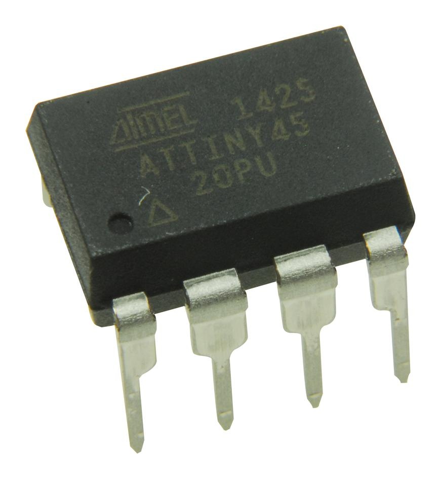
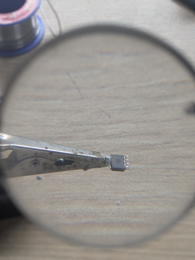
The ATtiny45, as you can see, does not have any USB ports or easy ways to interface. To program this specific chip, you actually need another chip that can interface with your computer and can translate the signals received over USB and write them onto the flash memory of the microcontroller
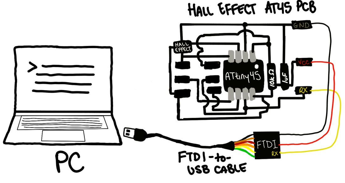
The ATtiny45 itself needs a special FTDI cable to receive power/GND from the computer, and it can send very simple pulses of data through the D+/D- of a USB cable, but not complex enough to be used to program the device itself.
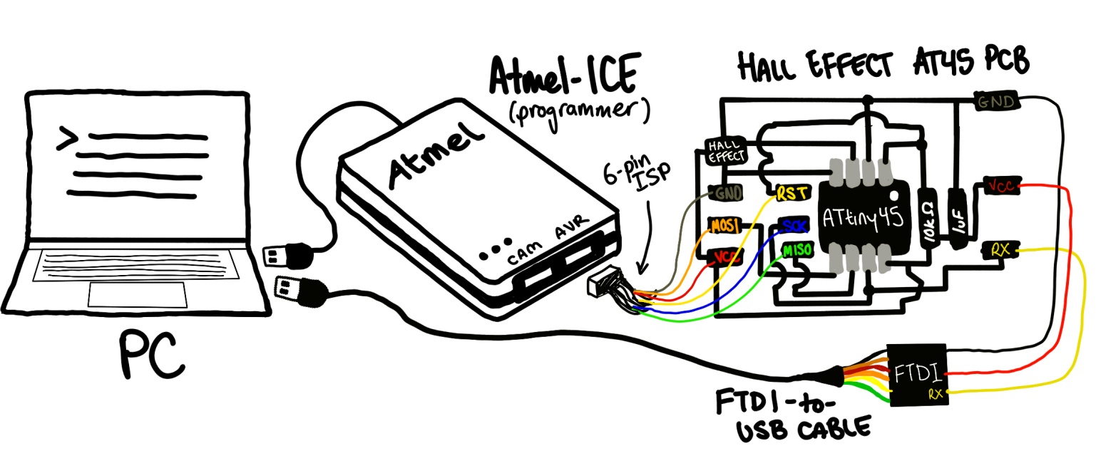
In essence this is how flashing the chip works:
- The Atmel-ICE pulls the ATtiny45's reset pin to 0V/GND, this stops the CPU of the chip, preventing it from executing any instructions that might have already been on the chip.
- The Atmel-ICE pulses the clock pin, providing a rhythm for the communication about to come
- The Atmel-ICE is able to now send raw bytes of data in assembly to the MOSI (master out, slave in) pin
- Your PC compiles the code you want (in this case, it was written in C) into binary and sends the bits into the flash memory, essentially one at a time in sync with the clock cycle, until the program has been transferred.
- The Atmel-ICE releases the reset pin, the CPU on the ATtiny45 begins at the top of the flash memory instructions and begins executing the new code line by line.
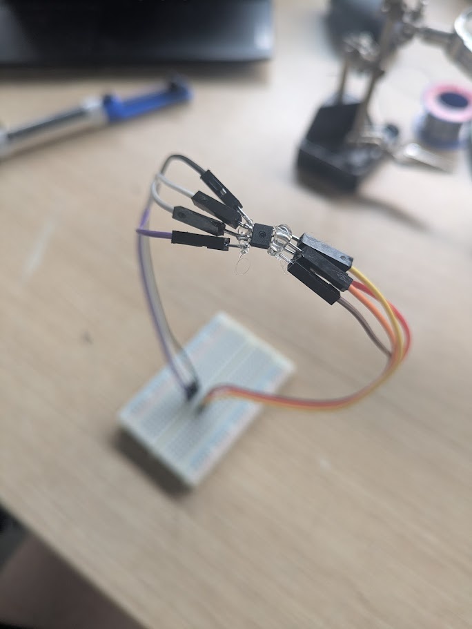
➔ Hall Effect Sensor
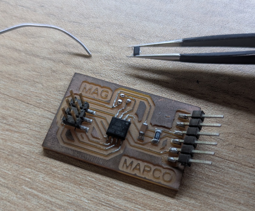
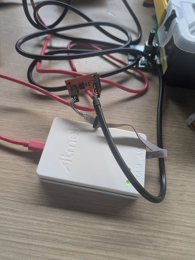
For my first test on a chip, I used one of Jorge's pre-assembled circuits that included a Hall Effect sensor wired to one of the data lines of the ATtiny45. In a nutshell, this little sensor can responds to magnetic fields in an analog range, passing the affected voltage to the data pin, so all I needed to do was pass instructions to the chip to read that voltage and translate it to something that could be sent over a serial connection.
I used code from the 2017 archive of the Fab Academy course (you need the C file, makefile and the python file to make this work) and compiled it using a program called avrdude, which takes the C code and translates it to binary (hex). C code is not fun to read, but I took some time to interpret each line. In essence, this program begins a serial connection over UART on one of the I/O pins (start bit is low, then 8 data bits, then stop bit is high - so one byte always looks like this: 0XXXXXXXX1), then begins sampling the pin that the hall effect sensor is wired. It performs this sampling over many clock cycles and then creates a sum of many readings (perhaps for better resolution?), then begins sending the 32-bit sum over serial.
Toolchain for the ATTiny42: C Code -> Compiler -> ELF (Executable) -> ObjCopy -> HEX -> Avrdude -> Chip
To use avrdude, you need a makefile (provides compilation instructions), some code (the C code mentioned above), and you need to tell the program which programmer/interface you're using, since there is more than one kind of way to do this! You execute the compilation instructions like this:
sudo make -f hello.hall.45.make program-ice
This command, inturn, calls on these arguments in the makefile.
program-ice: $(PROJECT).hex
    avrdude -p t45 -P usb -c atmelice_isp -U flash:w:$(PROJECT).c.hex
avrdude can be used to compile code for many different chips so the arguments for this command can be interpreted like this:
t45: tells the compiler which chip we're working with, so it knows to target the first register at 0x1B
-P usb: using the Atmel-ICE over USB, not a COM port
-c atmelice_isp: using the ISP protocol, essentially old school 6-bit flashing
-U flash:w:$(PROJECT).c.hex: target the flash memory, and write the C program
Once the chip is flashed, you need a way to interpret the 32-bit signal that is being sent over USB, so you need to run a python script that can display the output in a human readable format, which in this case is a bar meter. This is the command you run:
python3 hello.hall.45.py /dev/ttyUSB0
This script, again taken from the 2017 archive, opens the receiving end of the serial connection, waits for the low bit, 8 bit, high bit structure we spoke about in the C code, and then converts it into a decimal number, and does a little bit of math to draw that number as a red/blue box on screen, proportional to the highest and lowest values (the sensor does have polarity with north and south magnetic fields) in a updating bar meter.
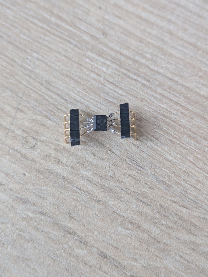
ATtiny412
My next step after cutting my teeth on the ATtiny45 was to jump to the ATtiny412. While both are 8-pin SOIC chips, the difference with the latter is that it can be programmed directly with UPDI (Unified Program and Debug Interface), meaning I could flash the device with instructions without a dedicated programmer, I could talk directly to the chip more or less over USB. The ATtiny412 also differs in that it has a bit of a faster clock speed (up from 8 MHz to 20 MHz), but the rest of the physical specifications are largely the same as the ATtiny45.
The problem: I didn't have any prefabbed boards with an ATtiny412 soldered to it to work with. So my solution, as a high school teacher who primarily teaches Arduino and microelectronics using breadboards...
➔ Breadboards!!!
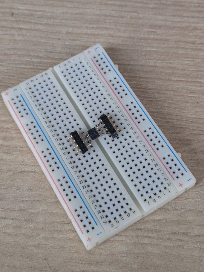
I understand why we shy away from breadboards at Fab Academy, but I couldn't pass up on what Neil said in lecture earlier this week. Breadboards allowed!!! I still do not have a reliable way to etch my own PCBs in my classroom back in Toronto (hoping to get an xTool laser cutter for either direct ablation or mask-based chemical etching), so in the meantime, breadboards still remain supreme in my eyes!
➔ Toolchain
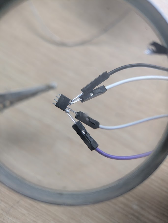
As I mentioned before, we can utilize the ATtiny412's native UART support to flash and listen to the chip using the same cable. The rick here is using a FTDI cable, and switching back and forth between the RX (receive) and TX (transmit) lines of the cable on two different pins of the ATtiny412.
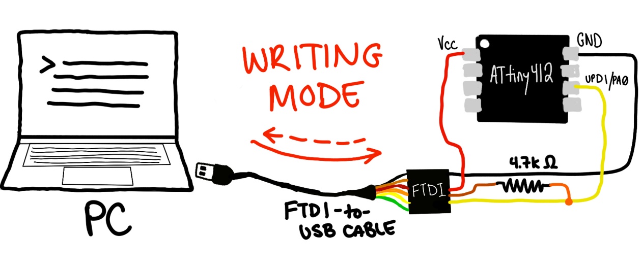
This effectively allows us to use the device in two modes, a write mode where we bridge the RX and TX cables with a 4.7k Ohm resistor (to prevent short circuit), allowing the computer to send the program via TX and the ATtiny able to reply/confirm down the same line through the RX.
For starters, I would try writing my own "Hello, World!" for this chip. Using some of the other examples on the Fab Academy site as a starting point.
#define F_CPU 20000000UL
#define BAUD_RATE 9600
#define USART0_BAUD_RATE(BAUD_RATE) ((float)(F_CPU * 64 / (16 * (float)BAUD_RATE)) + 0.5)

#include <avr/io.h>
#include <util/delay.h>
#include <string.h>

void USART0_init(void);
void USART0_sendChar(char c);
void USART0_sendString(char *str);

int main(void) {
    CCP = CCP_IOREG_gc;
    CLKCTRL.MCLKCTRLB = 0;
    USART0_init();
    while (1) {
        USART0_sendString("Hello, World!\r\n");
        _delay_ms(1000);
    }
}

void USART0_init(void) {
    PORTA.DIR |= PIN6_bm;
    USART0.BAUD = (uint16_t)USART0_BAUD_RATE(BAUD_RATE);
    USART0.CTRLB |= USART_TXEN_bm;
}

void USART0_sendChar(char c) {
    while (!(USART0.STATUS & USART_DREIF_bm));
    USART0.TXDATAL = c;
}

void USART0_sendString(char *str) {
    for(size_t i = 0; i < strlen(str); i++) {
        USART0_sendChar(str[i]);
    }
}
We can then flash the chip using a similar process as the ATtiny45. We compile the code using avr-gcc
avr-gcc -mmcu=attiny412 -Os -DF_CPU=20000000UL -o hello.elf hello.c
-mmcu=attiny412: just like avrdude, this tool can be used to program many different microcontroler units. In this case, this argument is just telling the compiler to ensure the instructions will begin at memory address 0x0400.
-0s: Apparently this argument slows down the compiler to ensure accuracy and small size over speed
DF_CPU=20000000UL: This is the frequency the chip runs at, as we defined earlier when comparing it to the ATtiny45
Then we go onto translating the .elf into .hex using:
avr-objcopy -O ihex -R .eeprom hello.elf hello.hex
-0 ihex: Converts the binary elf into actual hexadecimal (e.g. 1111 = F)
R .eeprom: This program is actually stored in EEPROM instead of flash
and finally the script that actually programs the chip over this UART connection:
pymcuprog write -d attiny412 -t uart -u /dev/ttyUSB0 --erase -f hello.hex
-d attiny412: specifies device (again, looking for a particular register to begin on)
-t uart: Slow pulse logic necessary for our little RX/TX hack, necessary when we're not using a dedicated programmer
-u /dev/ttyUSB0: This could differ on your machine, this is just where mine was plugged in
--erase: Wipe the memory before writing
-f hello.hex: The hex file we generated in the last step
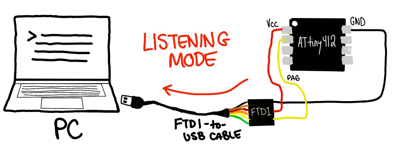
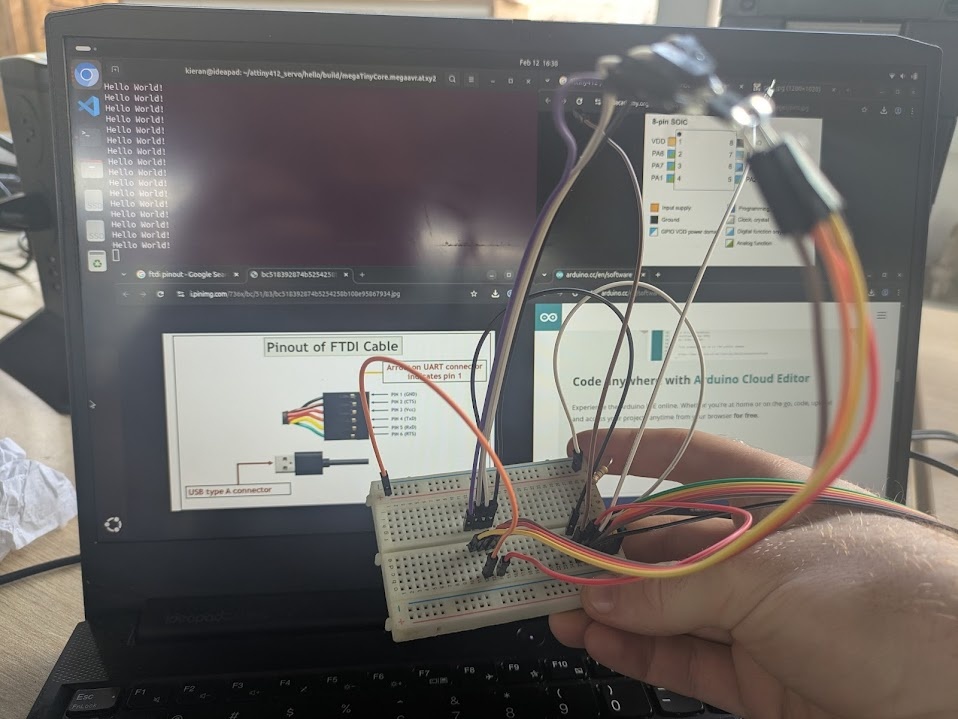
Once the code is flashed, we need to do a little quick swap to turn our FTDI cable into a listener, instead of a talker. For this, we just need to remove our little bridged resistor and connect pin 2 (PA6) of our ATtiny412 directly to the RX of our FTDI cable (no TX needed). Then we can use a python library to listen on the port at the correct baud rate.
python3 -m serial.tools.miniterm /dev/ttyUSB0 9600
The result:
Hello, World!
Hello, World!
Hello, World!
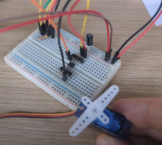
➔ Servo Motor
For my next magic trick, I wanted to try getting the board to control an output device using one of it's many available pins. It was around here that I read online that you can use the Arduino IDE to program the device directly - and I could just code in C++ the way I would normally with an Arduino Uno (was getting sick of plain old C, especially with how much work it is to enable serial communication). Wiring and programming the servo at this point was trivial.
#include <Servo.h>

Servo myServo;  // Create a servo object
const int servoPin = 1;

void setup() {
  Serial.begin(9600);
  myServo.attach(servoPin);
}

void loop() {
  Serial.println("0 degrees");
  myServo.write(0);
  delay(1000);

  Serial.println("90 degrees");
  myServo.write(90);
  delay(1000);

  Serial.println("180 degrees");
  myServo.write(180);
  delay(1000);
}
To set this up in the Arduino IDE:
1. In the tools menu, click on Board and select "ATtiny412/402/212/202"
2. Under chip, select "ATtiny412"
3. Under clock, select "20 MHz Internal"
4. Under programmer, select "SerialUPDI - 230400 baud"
5. Then verify and upload your code using the checkmark and arrow buttons!
And you should have a moving servo motor! Unless you're me and run into annoying issues. If you can't get avr-gcc running natively in your terminal, switch to the Arduino IDE. Also, check your wiring if you're using a breadboard! 90% of problems fixed by just reseating a resistor or two.
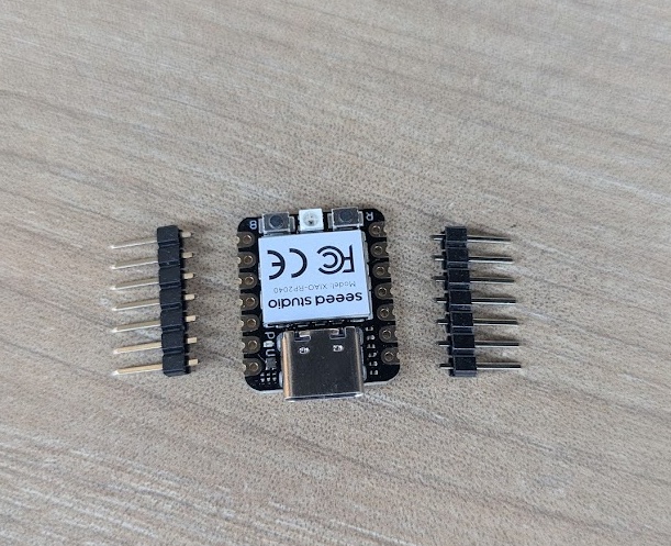
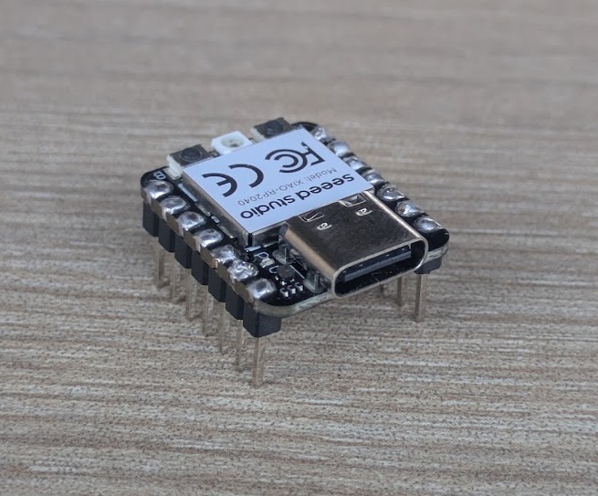
RP2040
If you've been on the same journey as me thus far, rocking a linux distro, you can finally switch back to Windows now, as we're working with a toolchain that is a lot more straightforward and (at least to me) familiar. The XIAO Seeed Studio RP2040 is a 32-bit ARM based chip which means we can work in high-level langugages like Python (good riddance C). This package also has a native USB controller built right into the chip, so there's no need to create, use or hack our way into programming it. We can just drag and drop code using the dedicated UF2 Bootloader. We're also working with a lot more power now, the RP2040 is dual core and clocks out at 133 MHz, supporting a whopping 2 MB (yes, megabytes!) of onboard flash memory.
You can also program the RP2040 directly from the Arduino IDE by following these steps:
- Hold the "B" button on the XIAO while plugging it in, this will start the device in bootloader mode, mounting it as a USB device with a filesystem
- In the Arduino IDE, click on File -> Preferences
- Add this URL to the "Additional Boards Manager URLs":
https://github.com/earlephilhower/arduino-pico/releases/download/global/package_rp2040_index.json - Go to Tools -> Board -> Boards Manager.
- Search for "pico" (specifically "Raspberry Pi Pico/RP2040" by Earle F. Philhower).
- Click Install (and any of the other required dependancies)
- Then under "Board", select "Seeed XIAO RP2040"
- and under "Port", select COM with anything that resembles the board's name
- You're ready to flash this hello world script!
#include <Arduino.h>

void setup() {

  Serial.begin(115200);
  pinMode(PIN_LED_G, OUTPUT);
  digitalWrite(PIN_LED_G, HIGH);
}

void loop() {
  Serial.println("Hello World!");
  digitalWrite(PIN_LED_G, LOW);
  delay(200);
  digitalWrite(PIN_LED_G, HIGH);
  delay(800);
}
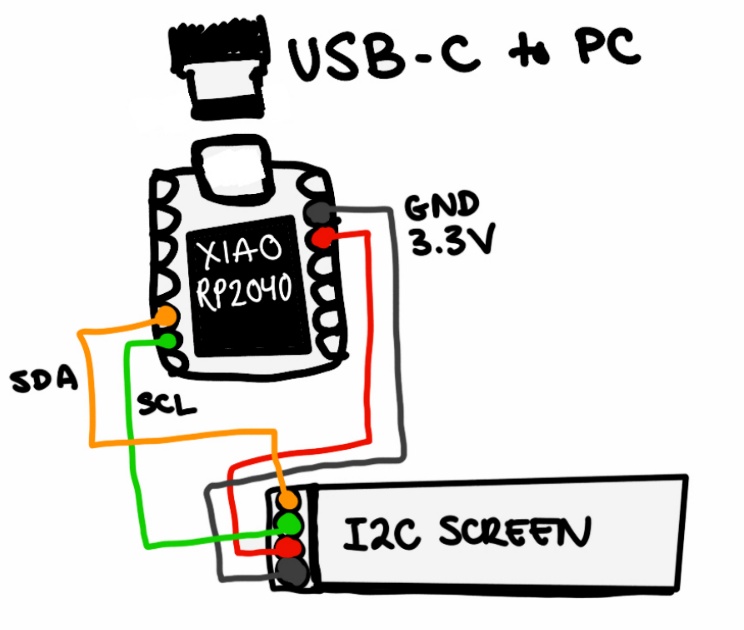
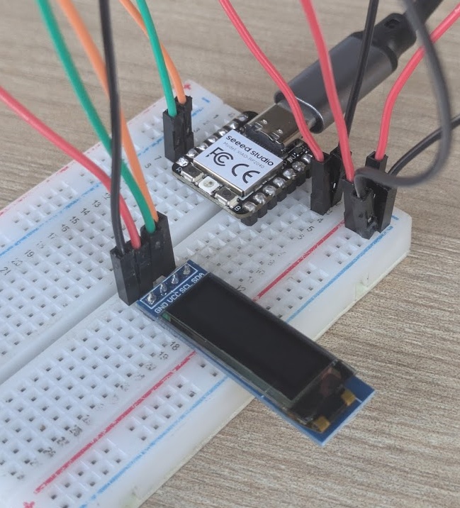
➔ I2C Screen
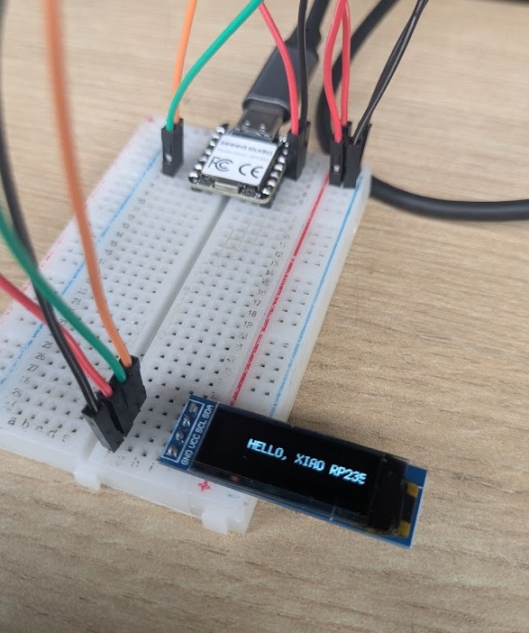
To wrap up the week, I wanted to interface with an output device: a 0.91" OLED display (128x32 pixels), since my final project will rely heavily on the use of a screen. Naturally, we're going to get it wired up using a breadboard.
I began working on the code for this in the same way I had been working, using the Arduino IDE and C++, but I grew frustrated with how slow the flashing process took. The Arduino ecosystem is vast, but it relies on a "Compile -> Upload" cycle. Every time you change a line of code, you have to wait for the compiler to rebuild the entire binary, and wait for it to communicate and flash the chip itself. It was not conducive to quick testing and learning a new output device, so I looked for other methods.
➔ CircutPython
CircuitPython, which turns the RP2040 into a USB drive that runs Python code on the fly, was the answer to my woes. To get it setup, all you need to do is:
- Download the .uf2 file for the Seeed XIAO RP2040 from circuitpython.org.
- Hold the "B" button, plug in the USB, and drag the .uf2 file onto the RPI-RP2 drive. It should automatically reboot and remount with new folders.
- Download the CircuitPython Library Bundle, unzip it, and copy these files to the lib folder on the board:
adafruit_ssd1306.mpy,adafruit_framebuf.mpy,adafruit_bus_device (Folder) - Now you can just open
code.pyin your IDE of choice and once you click save, it automatically reloads and runs the new code instantly. Sped up my dev process lots! - Try adding this code to
code.py, it is a basic i2c hello world
import board
import busio
import displayio
import terminalio
from adafruit_display_text import label
import adafruit_ssd1306
import time
i2c = busio.I2C(board.SCL, board.SDA)
display_width = 128
display_height = 32
display = adafruit_ssd1306.SSD1306_I2C(display_width, display_height, i2c, addr=0x3C)
display.fill(0)
display.show()
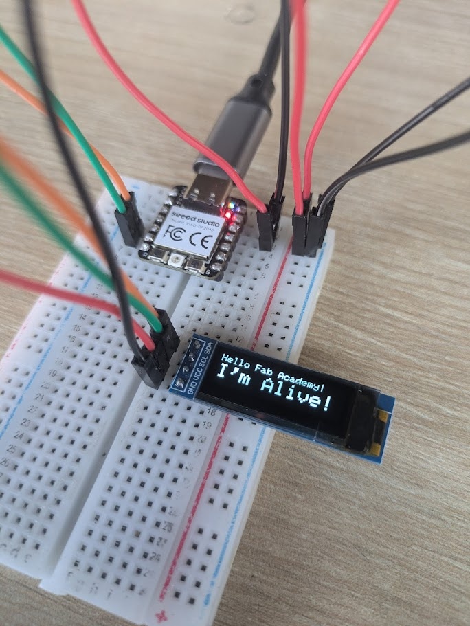
display.text("Hello Fab Academy!", 0, 0, 1)
display.text("I'm Alive!", 0, 10, 1)
display.show()
while True:
display.invert(True)
time.sleep(0.5)
display.invert(False)
time.sleep(0.5)
RP2350
For my final project, I will likely need to access all of the power I can get my hands on, so I wanted to try out the RP2040's beefier cousin, the RP2350, this one still offered by XIAO. This board boasts a slightly faster clock speed, double the memory, and more GPIO pins (despite it looking identical, there's actually accessible pads on the underside of the device that you can solder to).
➔ Pomodoro Timer
I was reflecting on my work habits this week (and in general), and decided I would adapt some healither break habits. I'm super interested in the work I'm doing in Fab Academy, but I often get too focused and forget to listen to my body. I'm also surrounded by beautiful nature here in Lima, lovely birds, and excellent sunshine. So I decided what the first cartridge would be for my final project: A Pomodoro Timer. For those unfamiliar, a pomodoro is a simple timer that counts in 25 minute, then 5 minute intervals. The goal of the device is to use the 25 minute block to focus purely on one task, no distractions or multitasking, then at the end of that block, you take a deliberate break for 5 minutes. Get up, stretch, or in my case: enjoy the Peruvian sunshine.
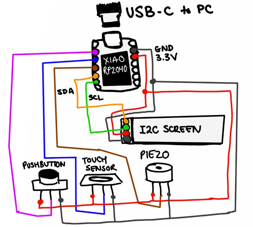
Wiring all the components is easy when you have a common Vcc and GND rail on your breadboard (another point for team breadboards, Neil). The button, touch sensor, and piezo all had their own PCBs with integrated transistors and resistors, which makes it easy to plug it directly in to a breadboard and send the signal line to one of the data pins on the RP2350.
For this project I would need a few more libraries:
- adafruit_ssd1306.mpy
- adafruit_framebuf.mpy
- adafruit_display_text
- adafruit_bus_device
- i2cdisplaybus.mpy
You can read more about how I am integrating the RP2350 and the pomodoro timer into my final project on my final project page.
The code for the pomodoro test app, which implements simple state machines to determine which timer to run and when to listen to the buttons, can be viewed here.

Conclusion
This was a seriously neat week, I'm happy to have had the chance to work with some of the older architectures. Kids these days simply don't get how easy they have it. The layers of abstraction were peeled away for me this week as I actually got to stop a CPU manually to feed it new instructions (with the Atmel-ICE). I'm happy I ultimately made the switch over to CircuitPython, as it's going to help me develop for my final project without ripping my hair out waiting for compilers (okay I know it's like 15 seconds more but that really adds up when you're trying to iterate or you make a million little mistakes like I do).
In terms of pedagogy (for my work back home), this week was a great exercise in balancing the "slow" way of doing things, digging through old forum archives, reading data sheets, etc. with this new fangled "fast" way of using LLMs to handle the menial stuff. I'm coming out of this with a much clearer starting point for my final project cartridge system and a lot more respect for the chips that don't just have a USB port.