Introduction
This week was all about using computer software to drive stepper motors in 2 axes to cut, burn or etch material to create designs or objects that can be constructed into 3D forms. It was also an amazing opportunity to practice parametric design, a natural next step from last week's learning on CAD. You can read about our group assignment at Fab Lab ESAN here.
[x] Demonstrate and describe parametric 2D modelling processes.
[x] Identify and explain processes involved in using the laser cutter.
[x] Develop, evaluate and construct a parametric construction kit.
[x] Identify and explain processes involved in using the vinyl cutter.

[ ] For my students: create visual aid for laser engraving and cutting settings
[ ] For my students: create visual aid to describe the different kinds of joinery
[ ] For my students: create a vinyl cutter "template" file for practicing (designing, weeding, etc.)
Machines
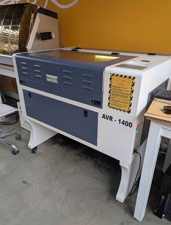
I had a lot of fun this week, finally getting my hands on some of the machines in the Fab Lab here at ESAN. This week, I primarily worked with three machines, specifications below. Jorge provided me with specifications for the older of the two machines, and with some tinkering and research, I was able to determine the rest.
Parametric Design
You can read all about my intro to real CAD software in last week's documentation but to summarize, Fab Academy is providing me an opportunity to learn some really powerful CADing techniques, including parametric design, which was a focus of this week's project.
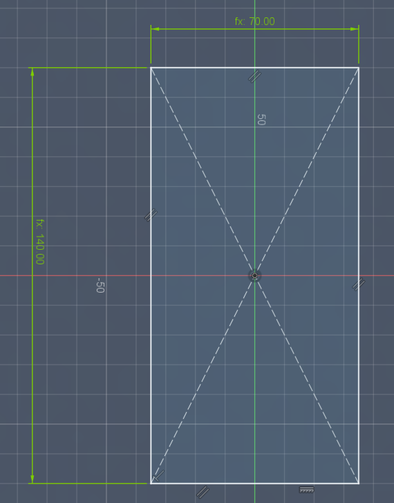
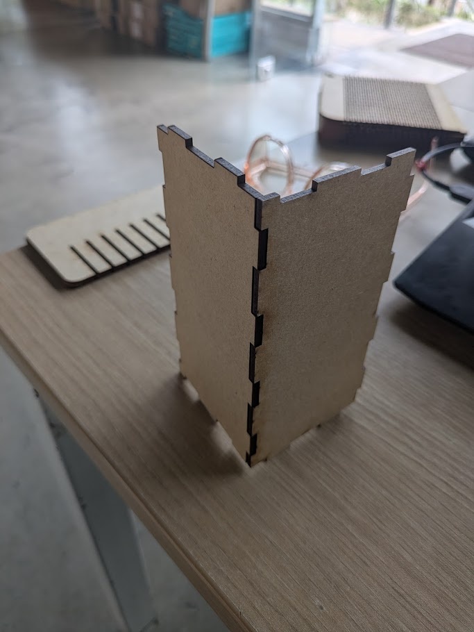
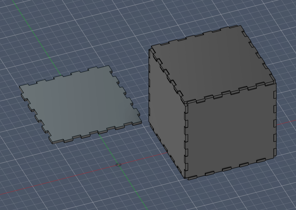
To start simple, I wanted to see if I could create a simple laser cut, press-fit box. I began working in Fusion, and with practice and trial/error, I learned and practiced a few key shortcuts when designing things that are meant to be scaled or dynamically resized/modified without needing to rebuild the whole model.

Define most (if not all) of your dimensions as parameters (i.e. like variables in a math function), that way you can make quick adjustments to a completed model without needing to recreate the whole thing.
➔ Parameters
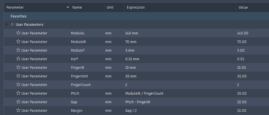
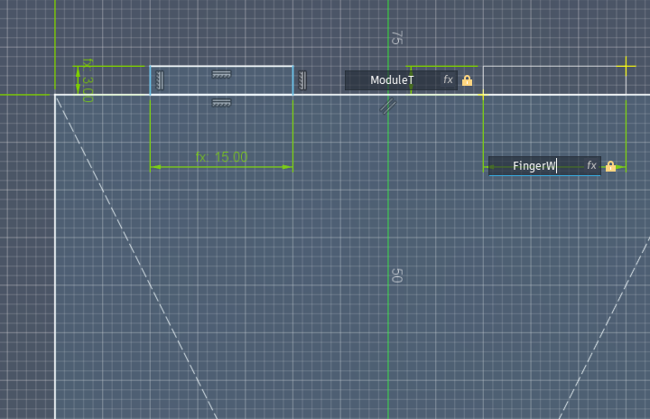
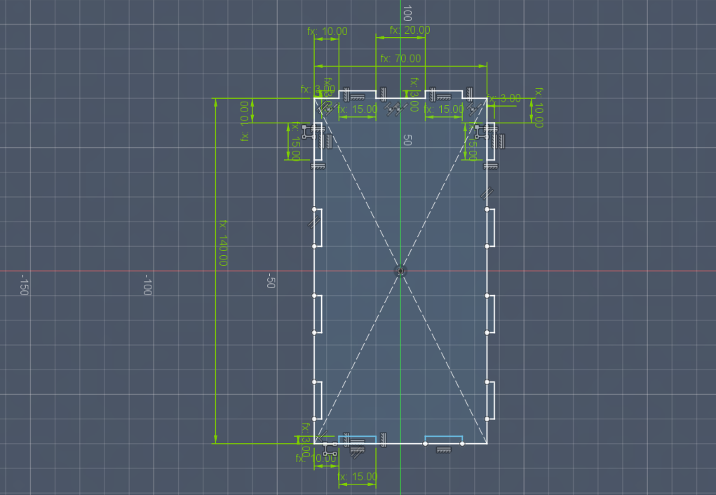
For my snap fit box, these parameters included:
ModuleL: The length of the wall for the box
ModuleW: The width of the wall for the box (defined as length/2)
ModuleT: The thickness of the material I would be using (also the length of the finger joints)
FingerW: The width of each of the joints
Pitch: The distance between each finger
and most importantly Kerf: the diameter of the hole left by the laser of the particular machine used.
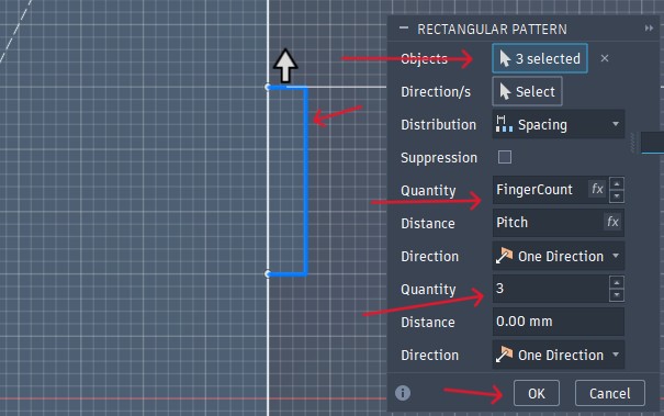
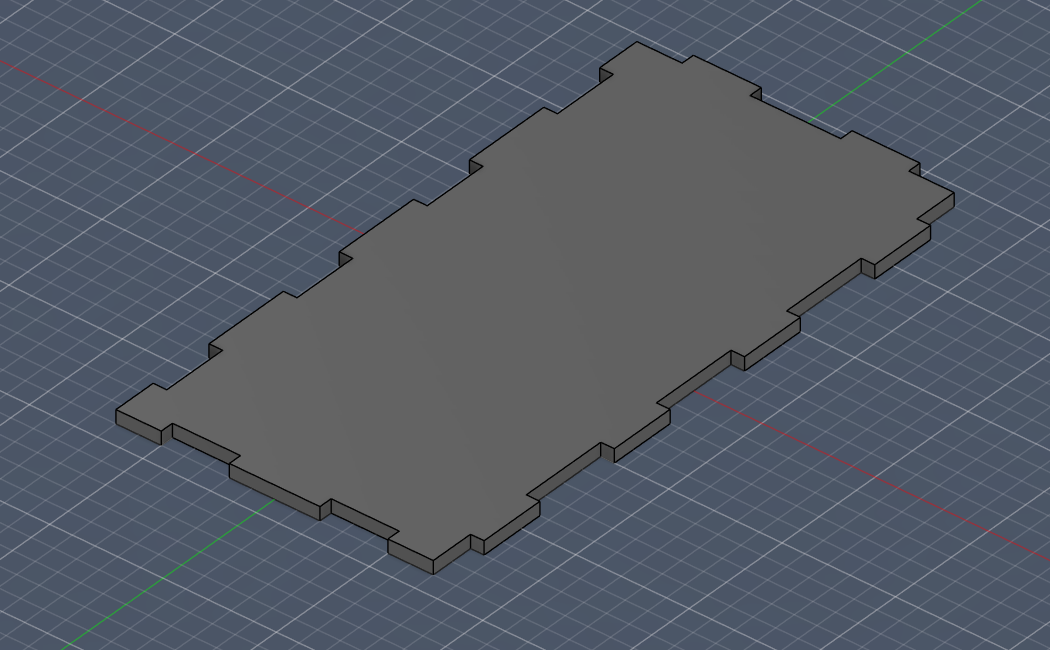
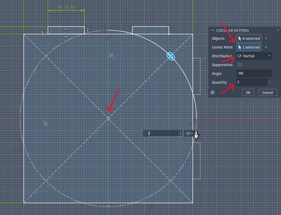
When you've got a feature that will repeat across your design, opt to use a pattern (rectangular/circular) to generate it, instead of manually copying/pasting it.
This was actually super fun to apply, because I could use parameters to define the number of teeth to "generate" on each edge based on how long the width parameter was.
Laser Cutting
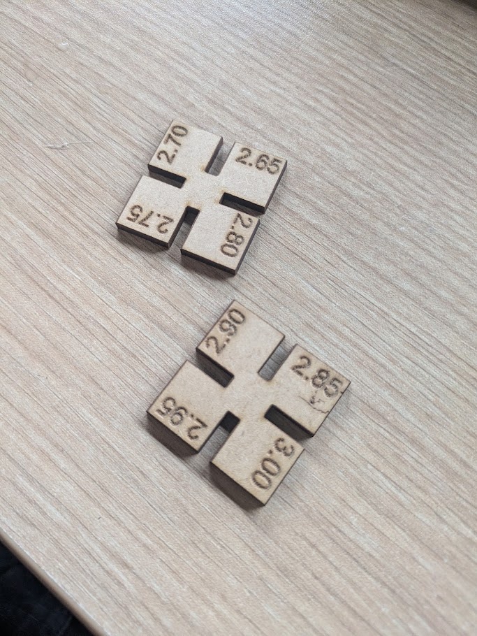
From here, I could export a 2D vector image of the design from Fusion and bring it over to the laser cutting station, which for my first few projects, I used ESAN's AVR-1400. Before I could actually submit that print though, I would need to test and measure the machine's kerf, so I modelled and designed a few little "kerf test tokens" that I could compare fits with.
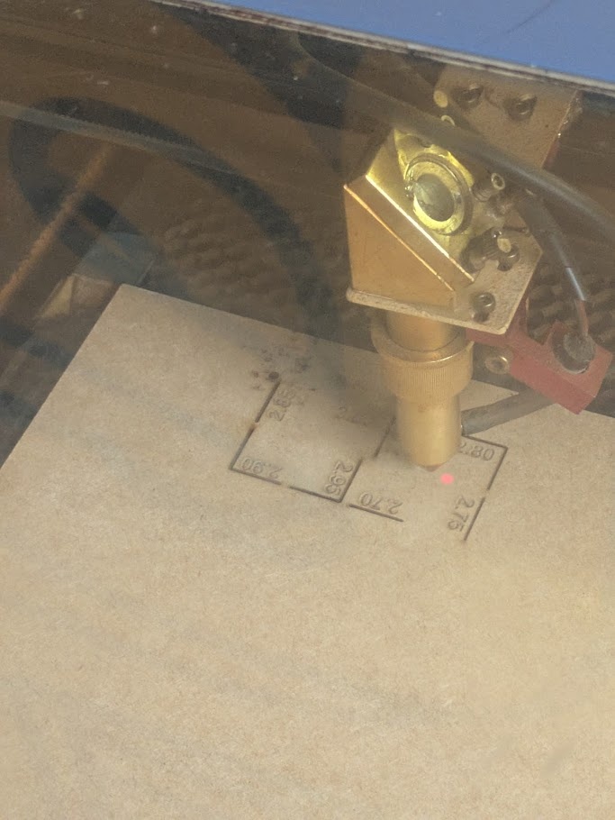
After selecting a suitable kerf (for the AVR-1400, it was about 0.17mm), I edited the parameter in Fusion and sent my .DXF file to the computer controlling the AVR-1400. Jorge has a special modified version of Corel Draw that generates G-code, rather plainly, and can control the stepper motors of the laser cutter. For cutting MDF, which was the material I chose to start with, we want to use a 75W power setting and have the laser move at 20mm/s. And here's my result:
Construction Kit
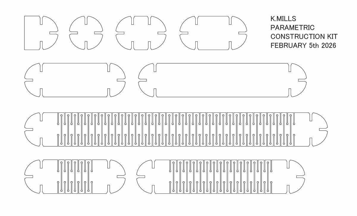
While CADing my first model, Jorge showed me these amazing samples of "living hinges" cut from MDF, that allow the material to bend, rotate and fold by carving out alternating chunks along the transverse axis. I was wowed by this and determined to try generating my own pattern in CAD for my parametric construction kit.
In my mind, I saw my kit having circular connecting joints, consistent widths, and differing lengths to play with. The intention was less practical and more artistic, to see what I could do with the material and where it would lead me.
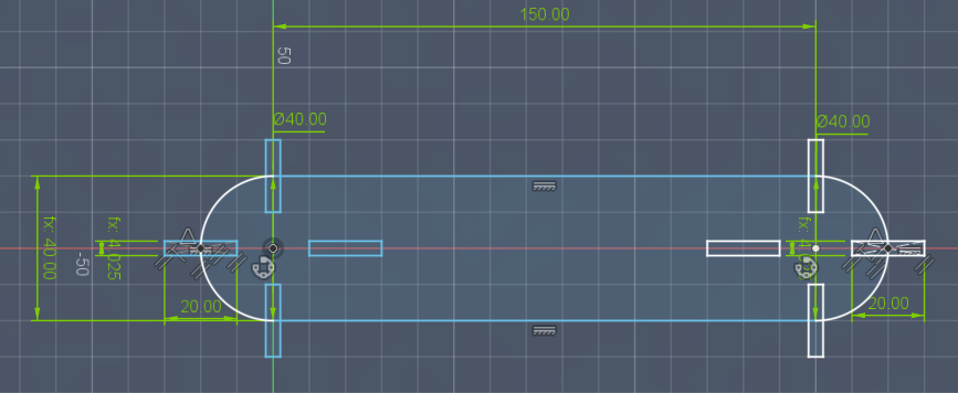
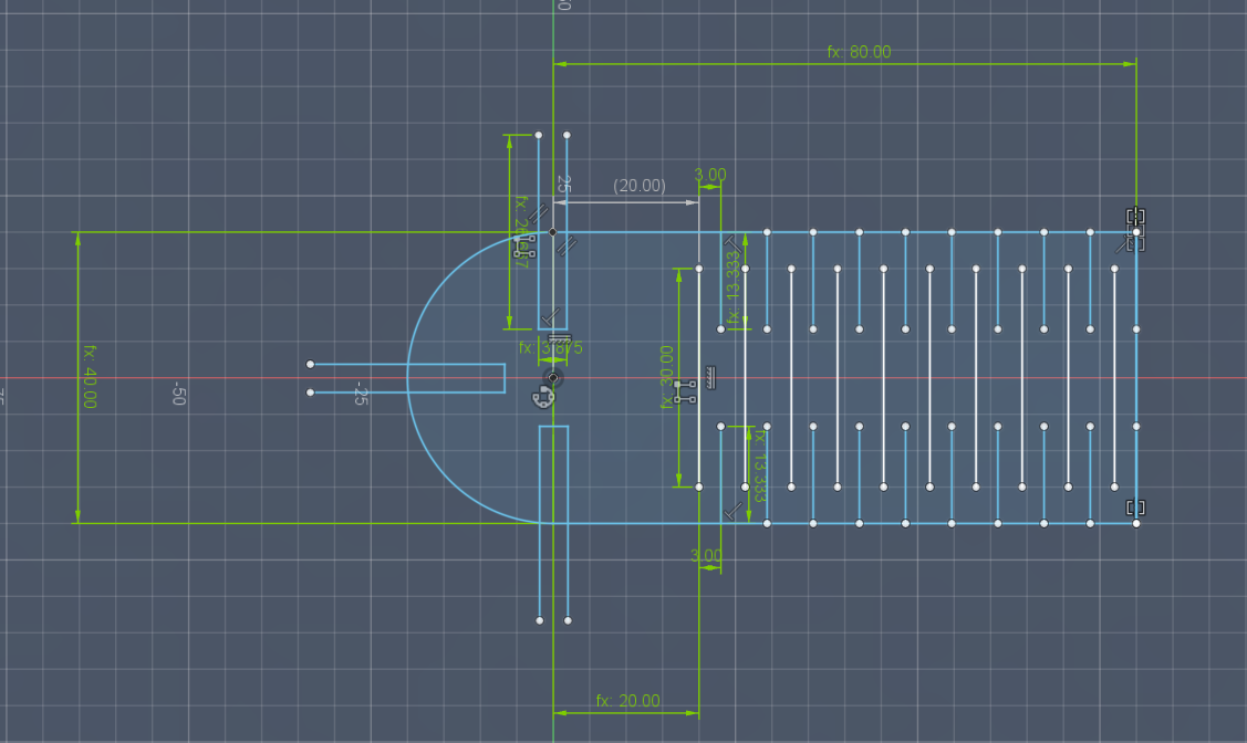
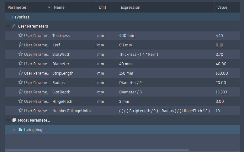
My process for the living hinges required more parameters to be defined. I wanted to be able to create construction "blocks" with differing lengths with and without the hinge applied, so I would need to parametrically define how to generate how many "hinge" units for a given length.
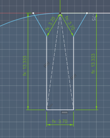
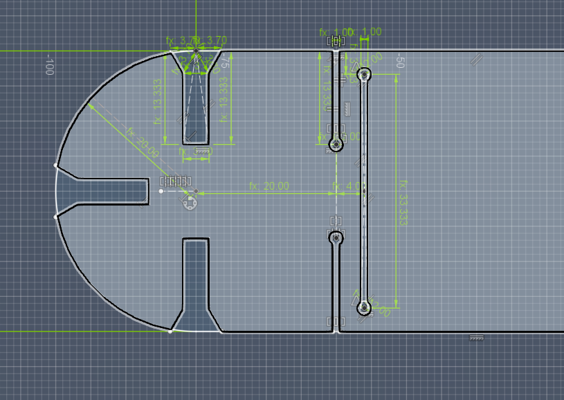
It was also here that I decided to add a fillet to the slots, as per the suggestion heard in the lecture this week. Since the slots could be generated on radial curves, I defined the chamfer as equilateral triangles that always had a fixed distance (the material thickness) apart from the centerpoint and slot edge.
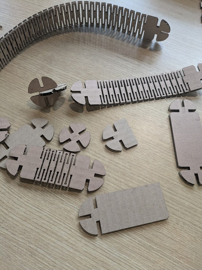
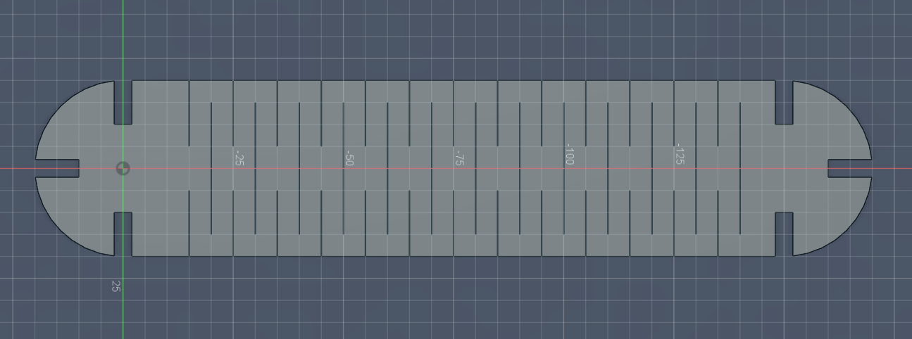
I created a few prototypes of the hinge and slot system using cardboard first (I really don't like overly wasting materials) and with a bit of back and forth, eventually developed a system that I was happy with. I opted to add these little "dog bone" terminals on the ends of each hinge gap, since I found the stress points on earlier models were always the 90 degree edges within.
Generating all different sizes of the kit was super easy! All I had to do was open up the parameters window and change two numbers (the length of the part, and a boolean to indicate if hinges should be generated or not).
I created 9 sizes to play with, 3 with hinges (80mm, 160mm and 320mm) and 6 without (20mm, 40mm, 80mm and 160mm, plus a basic unit and a basic unit with a flat edge that could be used as a "stand").
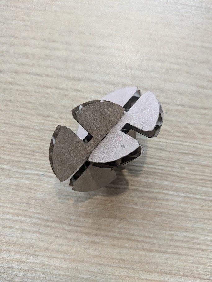
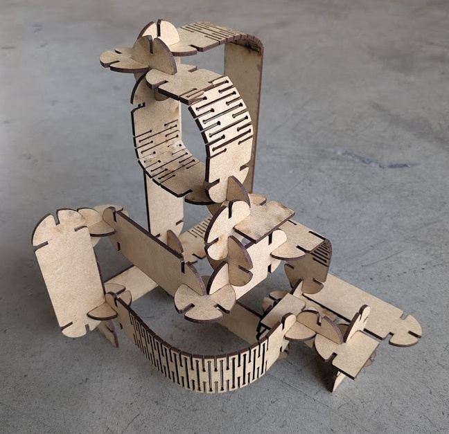
I spent an hour just playing with the kit, pressing different combinations of each together, and eventually created a simple sculpture to showcase the curves and bends. I think it turned out great!
Note: If you're noticing any "burn" marks, Jorge told me that the machine had not been cleaned a bit, so lots of sticky resin from the MDF was making it on to the underside of the print, and that it wasn't actually getting burned.
Engraving
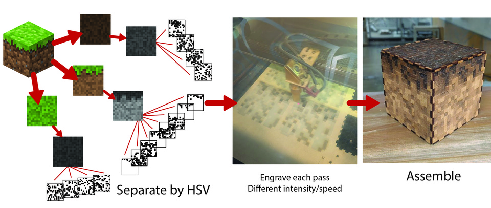
For engraving, I thought of an idea to create a press fit "Minecraft" grass block, where each colour of the original texture would correspond to a different laser wattage and speed, creating a monochromatic (and depth) effect.
Developing the box itself was the easy part. I employed the same techniques described above to create the box. The tricky part was now developing a way to assign the colours of an image to different intensities and speeds on the laser cutter. This was extra difficult because the software used to drive this machine could really only handle one set of parameters at a time, and I would need to manually start each pass configured with the correct beam intensity and speed. I guess this was a good practice, because there is no "set it and forget it" when it comes to laser cutting. You need to babysit the machine just in case!
Always be in arms reach of the laser printer, and wear eye protection if you are watching it directly!
I found 16px by 16px images of the top, side, and bottom textures for the grass block online, and then asked Gemini to help me write a python script to process the images into separate .SVGs that I could send to the printer.

Help me create a python script using Pillow to convert a series of 16px by 16px .PNG files into layered .SVGs based on their colour data, optimized for laser engraving. Resize each image to 100mm x 100mm using nearest neighbour resampling, iterate through each pixel and convert it to HSV. We will use 8 shades overall, the bottom 4 (lightest values) will be for all the "brown" pixels and the top 4 (darkest values) for all of the "green" pixels. Within each colour, determine the brightness/value of each and assign each pixel the closest of our 4 values. Draw each pixel as a rectangle filled with black and no stroke. Ensure all SVGs are 100mm by 100mm no matter the resulting image.
Once that was generated and sent to the computer, it was time to buckle in. Engraving this was not a quick job. I sat at the laser printer for almost 5 hours just waiting for each pass to be completed. In hindsight... this was easily something I could have done quicker on a newer machine that supported multi-setting passes. I could have probably used the built in software of these newer machines to process the colour images too, but hey -- I never said I wanted it easy! It was a fun learning experience despite the long wait. I got more hours on the machine, and that's what is important.
Here's the full process that I elected to do (and document):
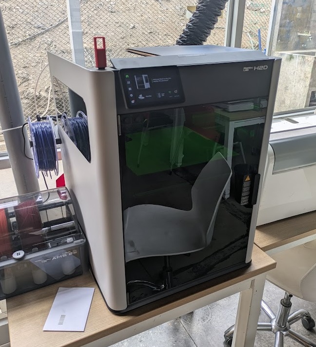
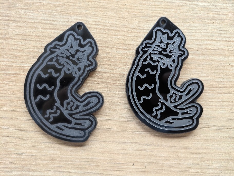
After the sticky MDF minecraft cube was assembled (and cleaned with isopropyl), I wanted to try out some more materials, and Jorge had just finished setting up the shiny new Bambu H2D, so it was time to play with vinyl! Over the weekend, I designed a little keychain of my cat, Loaf, whom I miss a lot while studying abroad!
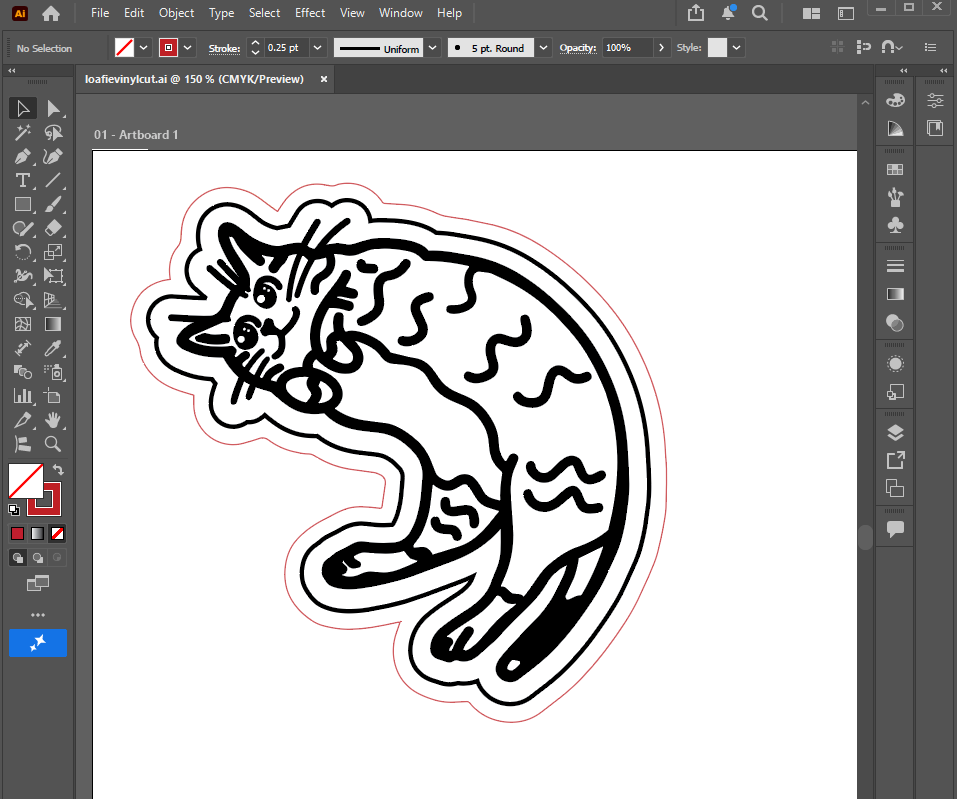
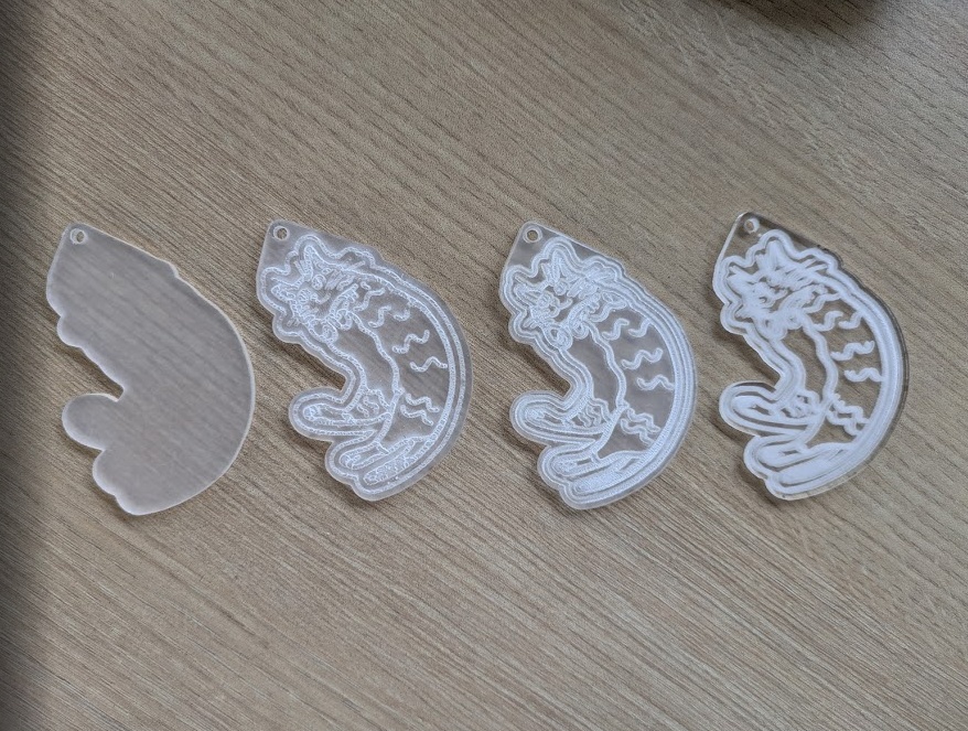
I traced out an image of her in Procreate, went over it a few times to get the line thickness right, then brought it into Illustrator where it was simple to vectorize it using Image Trace because I used such a thick, clean brush in Procreate. I ran a test pass in the AVR-1400 using clear acrylic (the H2D can't do clear materials because of the laser type) and then I realized (or Jorge told me) that you have to remove the plastic film on the material before engraving or cutting. Haha, maybe aerosolizing more harmful chemicals, oops.
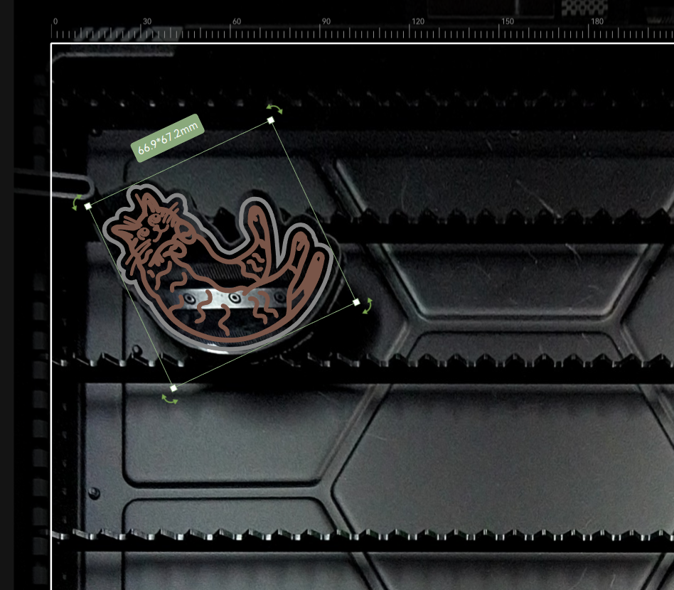
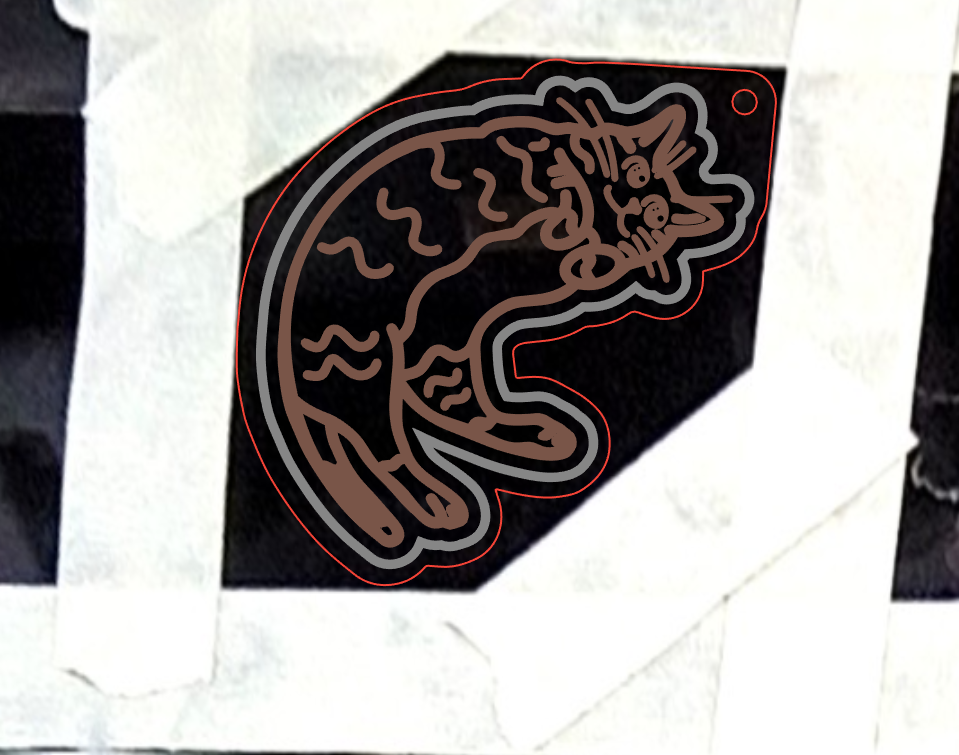
I wanted the keychain to be bidirectional (mirrored on both sides), so I had to come up with a clever way to do it. In the AVR-1400, I could create little "calibration" spots to line up the tool head, and then just pray. My first attempt I was off by maybe a millimeter. I tried again using black acrylic in the H2D this time, which has a handy little internal camera that lets you preview the cut using a picture of the build area. It's not super precise, and it was tough to see the cut lines so I had to add some tape to the edges of the design so I could properly line it all up, but it was enough to get the engraving done nicely on both sides.
Vinyl Cutting
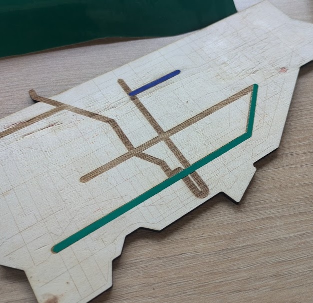
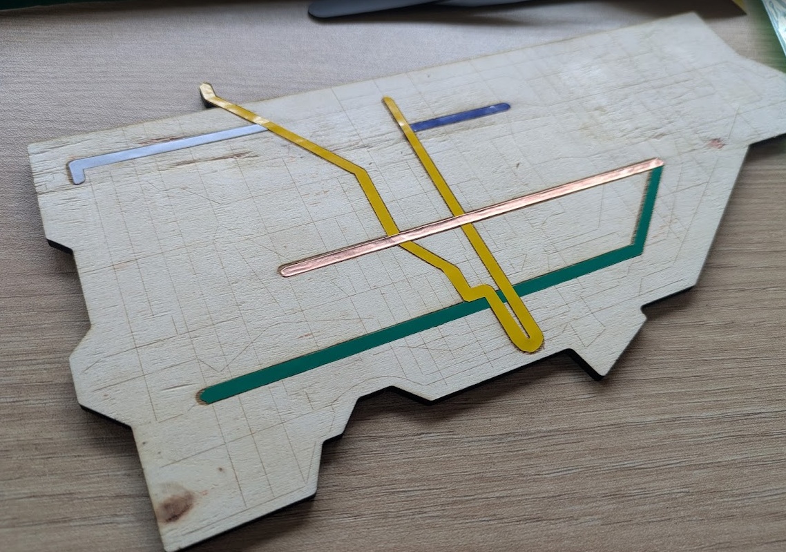
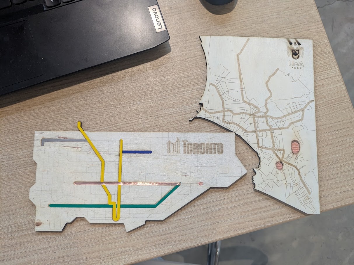
I have a Cricut Maker 3 in my classroom back in Toronto, so I'm not new to vinyl cutting, so I opted to mix mediums and create something that utilized the laser cutter, engraver AND vinyl cutting for maximum Fab Academy points. I had an idea to create cut outs of the transit maps for both Toronto (where I'm from) and Lima (where I'm living right now).
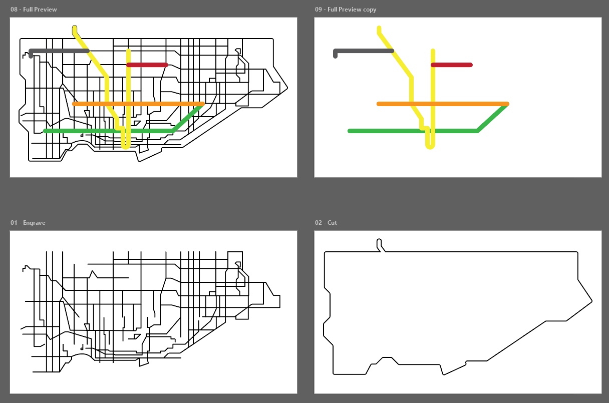
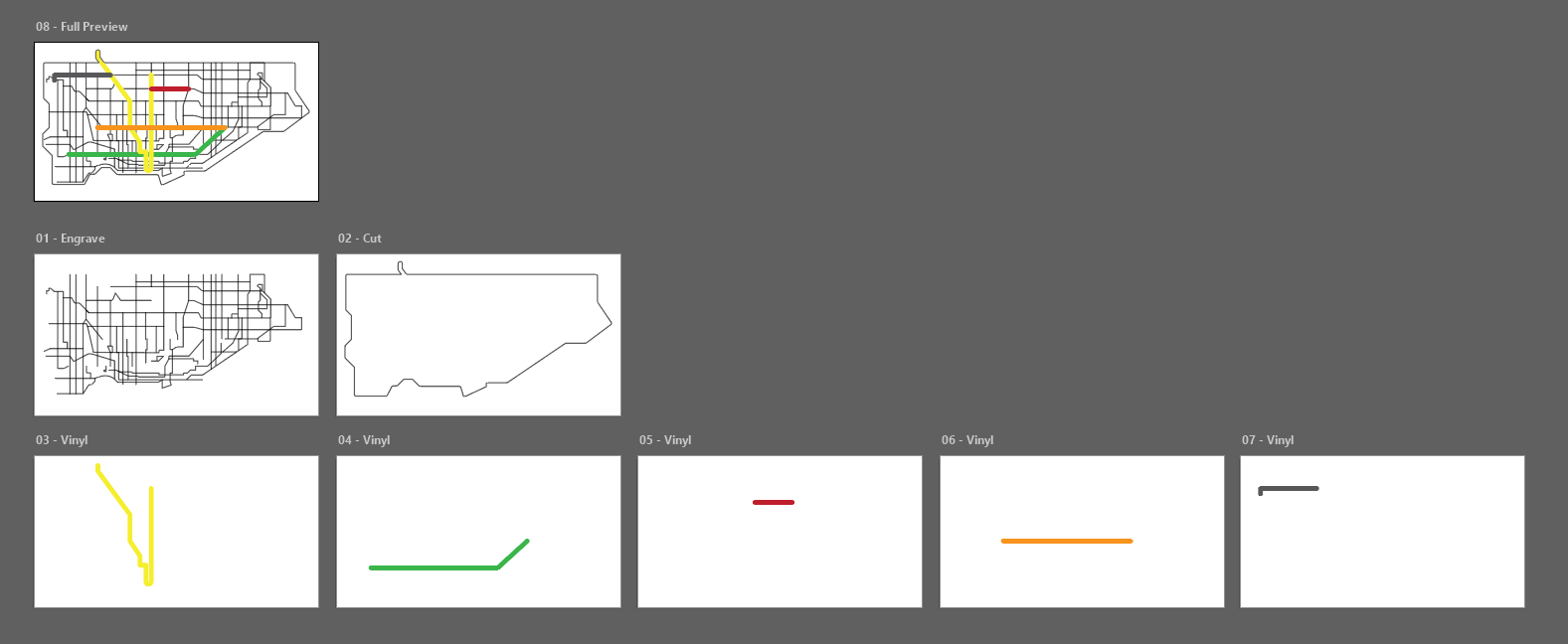
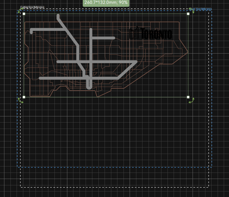
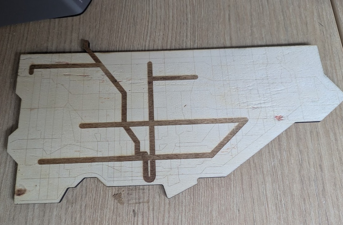
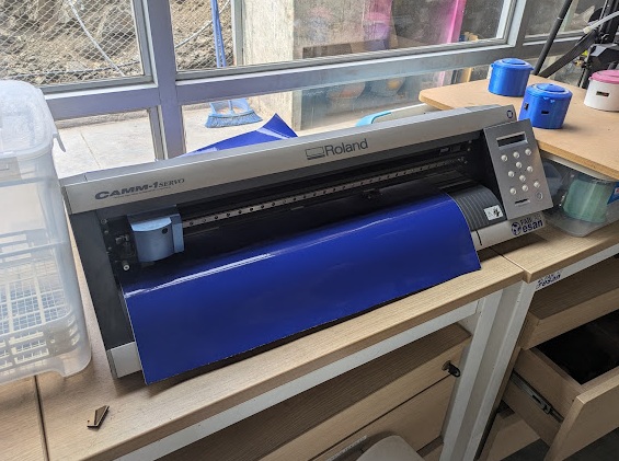
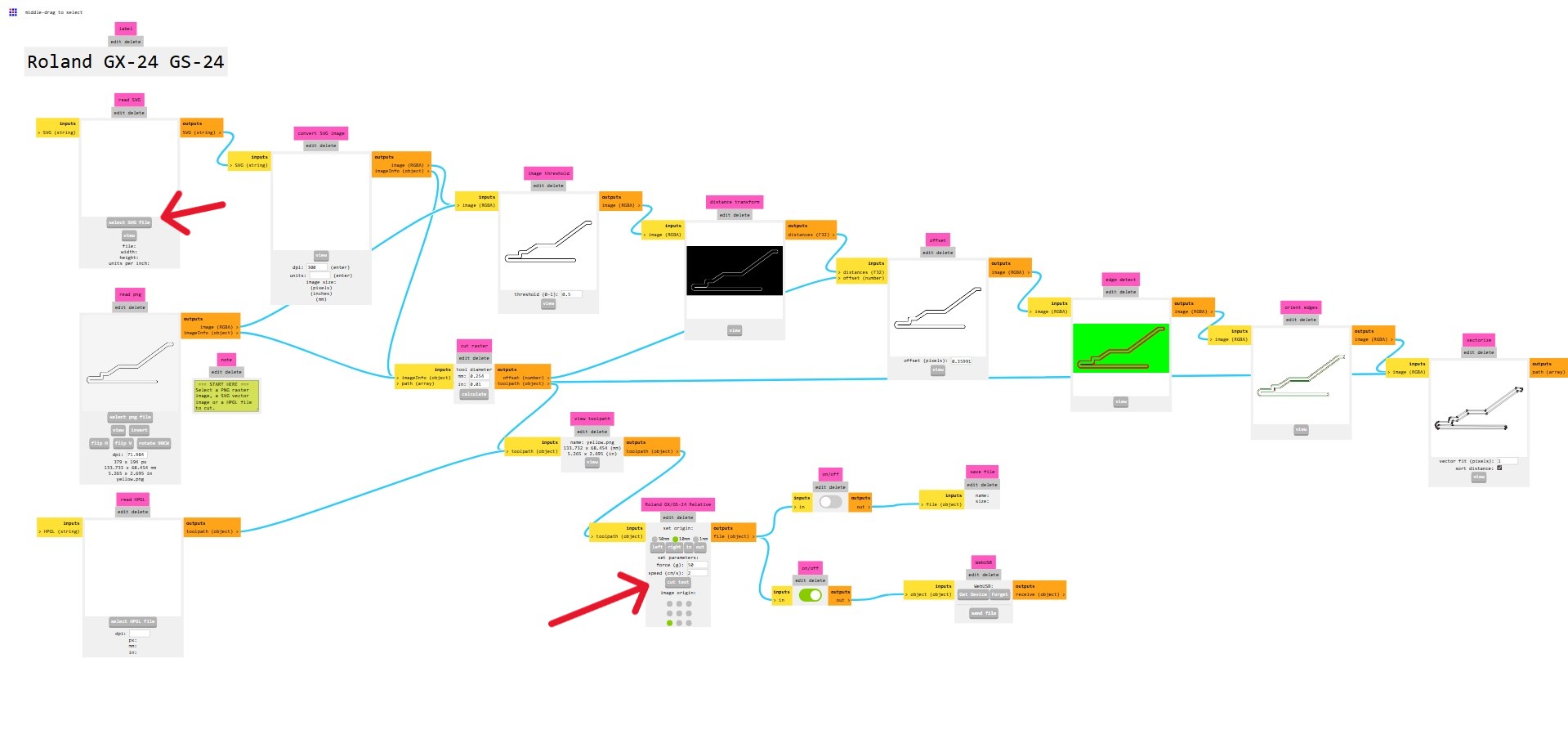
I traced out the map in Illustrator and separated the passes into different layers, separating the vinyl cut layers further into individual colours, then it was off to the machines! The H2D handled the engraving and cutting, while our new (old) friend, the Roland CAMM-1 handled the vinyl cutting. Honestly, I enjoyed using this machine much more than the Cricut, which crams their crappy software down your throat, trying to get you to purchase a subscription to their vector library. With the Roland, Jorge showed me a web based tool called Mods Project that could communicate with the machine over serial-to-USB (seriously!) and I could send the G-Code that way. To use this tool with the Roland, right click > programs > open program > Roland GX-GS vinyl cutters > cut, then modify the output by adding a usbserial module (right click > modules > add module > webserial, then hook up the file outputs from the Roland program to the inputs of this block).
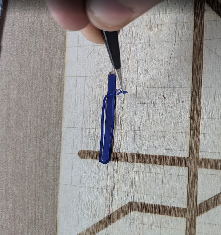
I sent 5 individual files to the printer on 5 different colours, one to represent each of Toronto's TTC subway/light rail lines (in honour of Eglinton Line 5 and Finch West Line 6 opening up recently!), then carefully weeded out each sticker and applied it to the birch board that was laser cut. Apologies to the Torontonians reading this, Jorge did not have any purple vinyl for Line 4 Sheppard, so blue it is (Insult to injury for Line 3 Scarbourough).
Of course I made one for Lima too, but I didn't include the vinyl yet because only 1.5 of the 4 planned metro lines are actually built. Hopefully soon all Limeños and Limeñas can hop on board and enjoy their trains soon! The bus rapid transit system here is also really cool, more cities should adopt it!
All the files for this week's creations can be found here:

Conclusion
Looking back at this week, it was a massive reality check on the difference between designing something and actually driving a machine. I had mentioned earlier that I haven't had the opportunity to work with a lot of subtractive manufacturing techniques until now, so getting to walk through a full toolchain finally was very exciting. I definitely met my goals for 2D modeling, but I learned the hard way that "babysitting" a laser cutter for five hours to make a Minecraft block is a special kind of dedication that I'd probably optimize next time with a more modern, multi-pass software. I think I would like to learn more about the maintenance and cleaning of these machines, as I did notice over time that the MDF was clouding up a lot of the laser machine's operation.
Number one take away from this week is that I won't be buying MDF for my laser cutter back in Toronto. Hopefully I can find some cheap acrylic or wood boards.