Week 12 — Mechanical and machine design
Group assignment for this week is on the Chaihuo Week 12 group assignment page. The rest of this page is my individual work.
Individual assignment
Week 12 is a group machine build. My individual deliverable is to document what I
contributed inside the team. The full group story, BOM, subsystem tests, firmware, and final
demo are on the
Chaihuo Week 12 group assignment page.
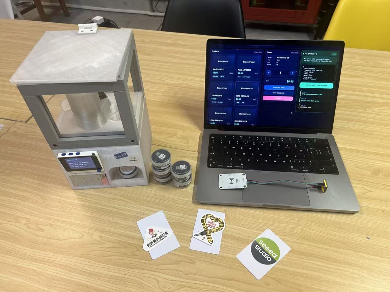
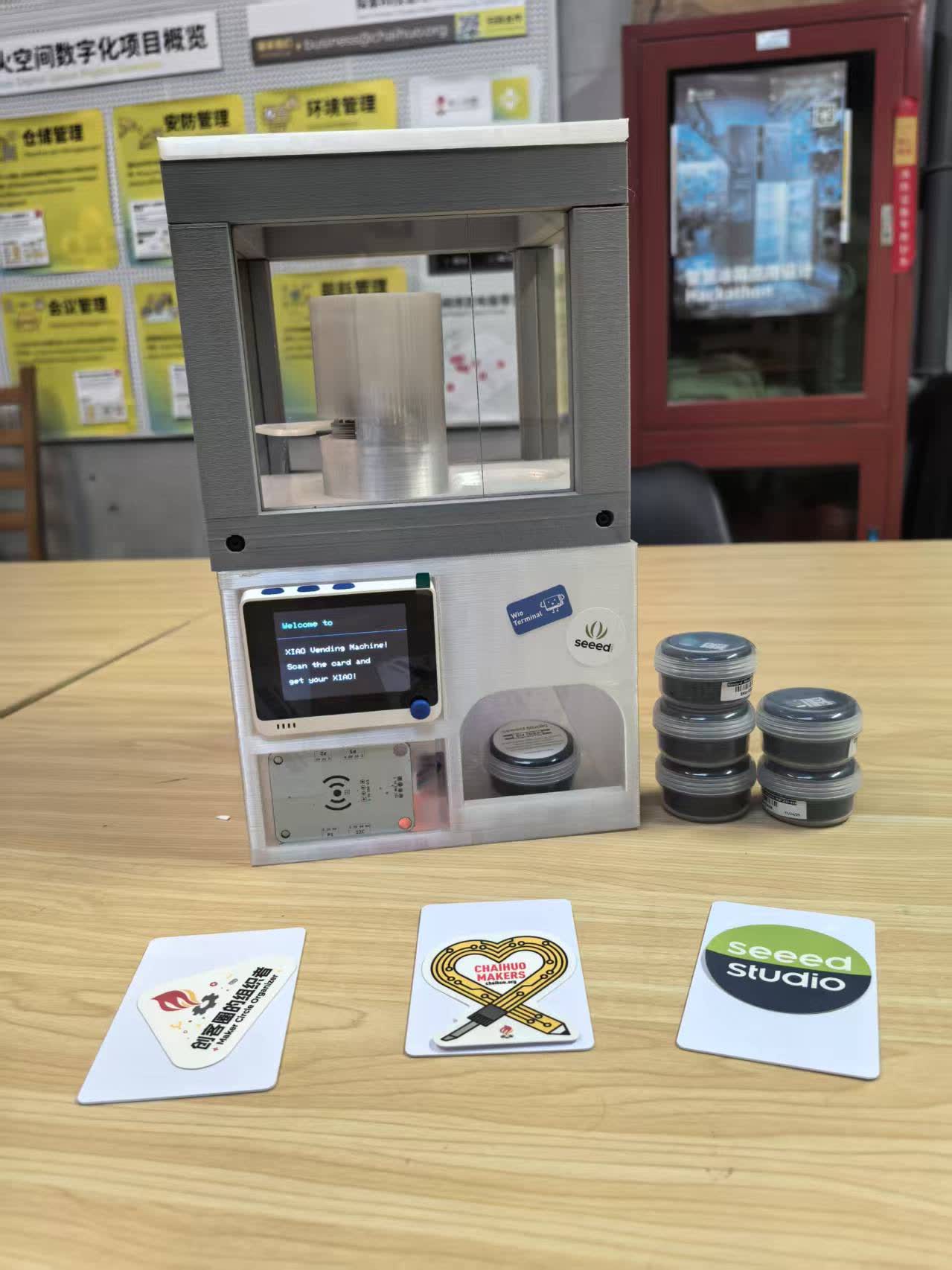
At Shenzhen Chaihuo we built an RFID-triggered XIAO board vending machine: tap a programmed
RFID card, the Wio Terminal checks a TRUE token in MIFARE block 4, then two
STS3215 serial-bus servos run the column gate and drop one XIAO board into the chute.
On the group timeline I worked mainly in phase 3 (assemble as one, test, integrate, record). The bench prototype already had RFID reads and servo motion working before enclosure work started. I took over once that flow was stable and routed the same topology into the acrylic enclosure without changing the firmware pin map.
| Requirement | How I covered it |
|---|---|
| Work and communicate effectively as a team | Kept the bench pinout, coordinated cable length with the mechanical layout, wrote down connector positions and closed-box test steps, and re-tested on two separate afternoons before freezing the harness. |
| Design, plan and build a machine | Integrated the group machine inside the acrylic column: Wio Terminal, Grove RFID reader, STS3215 daisy chain, and gate linkage mounted as one closed-box unit. |
| Analyse and solve technical problems | Tracked noisy RFID reads during gate motion, cable strain at the servo stroke, and service access with the lid closed. See the problem table below. |
| Recognise opportunities for improvements | Listed harness, EMI, and serviceability changes that would help the next enclosure revision and the group’s planned PC backend flow. |
My contribution: cabinet harness and integration
The job was not redesigning the firmware. I kept the pin and bus choices from the bench prototype, then made the wiring survive real mounting. That meant a continuous servo daisy chain, a short I2C run to the RFID board, a clean ground return, strain relief where cables leave moving areas, and enough service slack to open the shell without desoldering.
Working with the team
- Same pins and buses as the bench prototype; no random rewiring during debug.
- Cable length and bend radius were coordinated with the mechanical layout so gate motion did not tug connectors loose.
- Full gate stroke was checked before the lid closed; bad clearance looks like bad code.
- Connector positions and the closed-box test steps were written down for later debugging.
Bring-up sequence I used
- Power sanity check on the mounted Wio.
- RFID reader alive and readable on the Grove port.
- One servo move, then both servos through the full gate stroke.
- Closed-box card taps with LCD state visible through the acrylic.
I did not freeze the final harness until the merged sketch behaved the same on two
different afternoons, not only once. I did not rewrite the group firmware; I validated the
same buses and pins described in
vending_machine_final_code.ino on the
group source-code section.
System topology I wired
This matches the group architecture: one Wio Terminal as controller, Grove RFID on I2C, and two STS3215 servos on one serial bus with IDs 1 and 2.
| Node | Bus / interface | Role in the closed-box build |
|---|---|---|
| Wio Terminal | Grove I2C (Wire1) + UART servo bus; built-in LCD |
Reads RFID block 4, shows status on the LCD, drives SyncWritePosEx dispense cycles after Button A init. |
| Grove RFID reader | I2C address 0x28, 13.56 MHz |
Short harness run from the Grove port; leads routed away from the servo motor wires to reduce noise during gate motion. |
| STS3215 servos (×2) | Serial bus, daisy-chained, IDs 1 and 2 | Continuous bus through the column; enough service slack to open the shell without desoldering. |
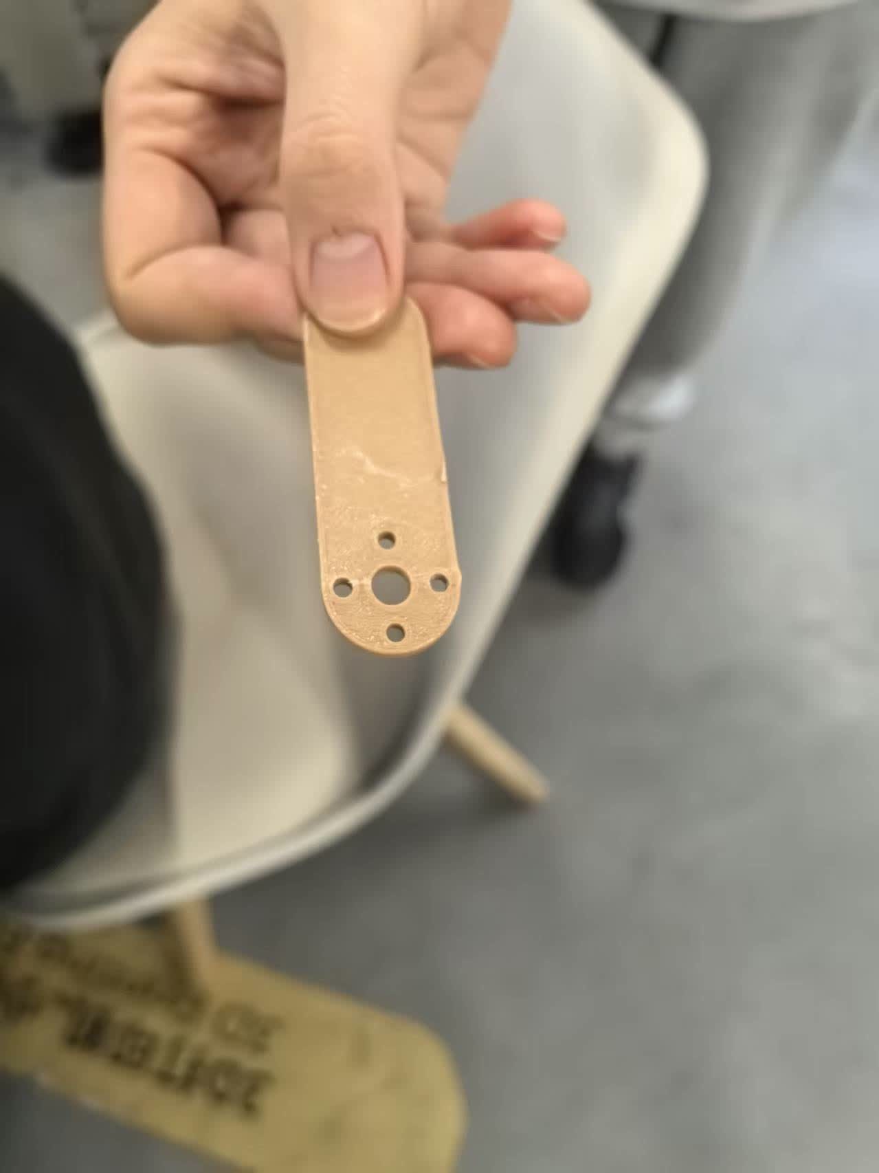
| 3D-printed servo arm + column gate | Mechanical linkage to servos | Full gate stroke checked before the lid closed so bad clearance was not mistaken for a wiring fault. |
Problems analyzed and how I fixed them
| Problem | What I checked | Fix or workaround |
|---|---|---|
| RFID reads looked unstable while the gate moved | Compared bench reads vs closed-box reads during HOME → TRIGGER → HOME servo cycles. |
Separated RFID leads from motor wiring and kept the reader harness short and away from the moving arm. |
| Connectors pulled loose when the gate stroked | Opened and closed the shell while watching cable bend radius at the column. | Coordinated harness length with the mechanical layout and added strain relief where cables leave moving areas. |
| Closed-box debugging was slow | Logged which Grove port, servo bus, and power paths were used after mounting. | Wrote a fixed bring-up order (power → RFID → one servo → both servos → closed-box card tap) and left connector labels inside the shell. |
Improvements I would make next
- Service loop: leave one removable panel or labeled breakout so the RFID reader can be swapped without unpacking the whole column.
- Harness dress: tie points along the metal columns so vibration from repeated dispense cycles does not fatigue Dupont ends.
- EMI: keep the RFID harness on the opposite side of the column from the servo bus for the whole run, not only at the Wio.
- Align with the group’s next step: a PC-side RFID writer and dashboard so cards are not hand-programmed before each test (see group section 9 on the Chaihuo page).
What I took from the week
- Machine weeks fail at the interface between mechanics and wiring more often than in the sketch.
- RFID leads routed away from motor wiring reduced noisy reads during gate motion.
- Labels and service slack matter as much as correct pinout when someone else opens the box later.