Week 11 - Networking and communications
Group assignment for this week is on the Chaihuo Week 11 group assignment page. The rest of this page is my individual work.
Individual assignment
My individual network is a wearable-to-host link for Brain Fog Insight Companion: MAX30102 on the band, Beetle over I2C, then BLE to a C3 bridge, then UART to the WROOM host.
I proved the packet format first with the WROOM acting as a direct BLE client. When the host also had to stay on WiFi for cloud voice calls, BLE and WiFi on the same chip made the UI stall. I moved BLE reception to a XIAO ESP32-C3 and kept the WROOM on UART only.
| Assessment item | Where it is covered |
|---|---|
| Demonstrate workflows used in network design | Network diagram, design workflow list, node split (wearable / C3 / host), and the C3 bridge decision after WiFi load appeared. |
| Implement and interpret networking / communication protocols | I2C sensor bus, BLE advertisement + GATT notify, UART forwarding, JSON packet format, and BAND,LINK,* status lines. Group I2C capture interpretation is under group assignment. |
| Connect nodes with addresses and local I/O | Three nodes in the node map; each has a fixed name, UUID, I2C address, or UART pin pair. |
| Board of my own design | WROOM host PCB documented in Week 16. |
| Hero shot, source code, problems and fixes | Hardware photos and live-test video; BrainFog_PIO firmware downloads; problems table below. |
Network design workflow
- Name the nodes and what each one is allowed to do.
- Wire local I/O on each node before testing the radio link.
- Use BLE between band and bridge because the band moves.
- Lock addresses early: device name, service UUID, characteristic UUID, I2C
0x57. - Prove sensor read, then BLE packet format, then move BLE off WROOM when WiFi voice goes live.
Wearable wiring and BLE transmit path
The bracelet is a Beetle ESP32-C6 plus a MAX30102 module. The sensor talks to the Beetle on I2C; the Beetle sends readings out on BLE.
| MAX30102 signal | Beetle connection |
|---|---|
| SDA | GPIO6 |
| SCL | GPIO7 |
| VCC | 3V3 |
| GND | GND |
| I2C address | 0x57 |
In firmware (BrainFog_PIO/beetle) the Beetle starts I2C on GPIO6/7, calls
MAX30102.getHeartbeatSPO2() about once per second, and builds a JSON line with
seq, hr, spo2, and temp. That line leaves the
band in two BLE forms:
- Advertisement manufacturer data: bytes
0xFF 0xFF 'B' 'F'plus packed seq / hr / spo2 / temp, so C3 can read the band before GATT connects. - GATT notify: the same JSON on characteristic
12345678-1234-1234-1234-1234567890acwhen a client is connected.
The band advertises as BrainFog_Beetle. GPIO15 blinks a status LED while I check the link.
Why I added the C3 bridge
The first version had WROOM scan for BrainFog_Beetle and parse notify packets itself.
That was enough for Week 11. Later the same board also ran WiFi for cloud voice. BLE scan plus WiFi
on one ESP32 made the host freeze during calls.
C3 now owns BLE: scan, filter by name, parse JSON, forward lines on UART at 115200 baud. WROOM only
reads Serial1 and runs the screen plus cloud voice. Wiring matches BrainFog_PIO/c3_ble_bridge
and Week 16: C3 D6 / GPIO21 TX to WROOM GPIO39 RX, C3 D7 / GPIO20 RX to
WROOM GPIO38 TX.
Network diagram
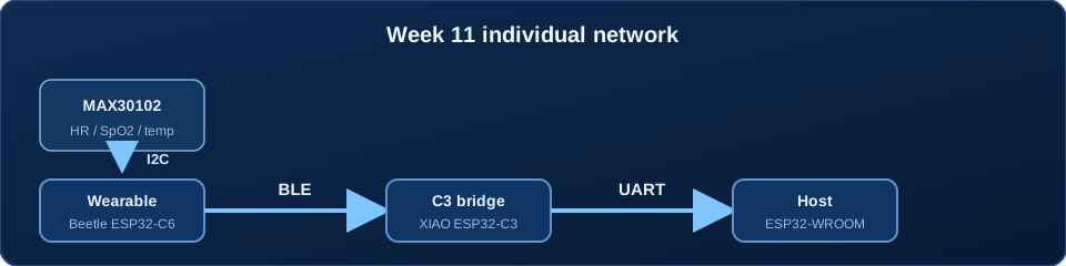
Node map
| Node | Board | Local I/O | Role in the network |
|---|---|---|---|
| Wearable transmitter | DFRobot Beetle ESP32-C6 | MAX30102 on I2C, status LED on GPIO15 | Reads MAX30102 over I2C, then transmits HR / SpO2 / temperature over BLE advertisement and GATT notify. |
| C3 BLE bridge | XIAO ESP32-C3 | UART TX/RX to host, optional USB debug serial | Receives wearable BLE, parses JSON, forwards lines to WROOM over UART. |
| Host receiver | ESP32-WROOM on my custom host PCB | Screen UI, USB serial debug, WiFi / cloud voice path | Reads UART lines from C3 and updates the host application. No direct BLE workload in the final setup. |
Addressing and protocol
| Address / ID | Value | Why it matters |
|---|---|---|
| BLE device name | BrainFog_Beetle | The C3 bridge only accepts packets from this advertised name. |
| Service UUID | 12345678-1234-1234-1234-1234567890ab | Defines the GATT service on the wearable. |
| Characteristic UUID | 12345678-1234-1234-1234-1234567890ac | Carries the JSON notify packets. |
| MAX30102 I2C address | 0x57 | Local sensor bus address on the wearable node. |
| C3 to WROOM UART | 115200 baud, C3 D6 / GPIO21 TX to GPIO39 RX, C3 D7 / GPIO20 RX to GPIO38 TX | Wired hop between bridge and host. |
| Advertisement payload | 0xFF 0xFF 'B' 'F' + seq + hr + spo2 + temp | Lets C3 parse wearable data from manufacturer data. |
| Packet format | {"seq":N,"hr":72,"spo2":98,"temp":32.5} | Parsed on the bridge and forwarded to the host. |
| Link status line | BAND,LINK,UP / BAND,LINK,DOWN | Tells the host whether the wearable link is currently alive. |
{"seq":12,"hr":72,"spo2":98,"temp":32.5}
On the C3 bridge I read manufacturer bytes after the BF marker as seq (16-bit), hr,
spo2, and temp (deci-degrees). When GATT is connected, the same fields arrive as JSON. The host
side prints parsed numbers like SEQ=12 HR=72 SPO2=98 TEMP=32.5. Wrong device name or
UUID means no connect; a dead sensor bus still sends JSON with zeros.
Hero shot and live test
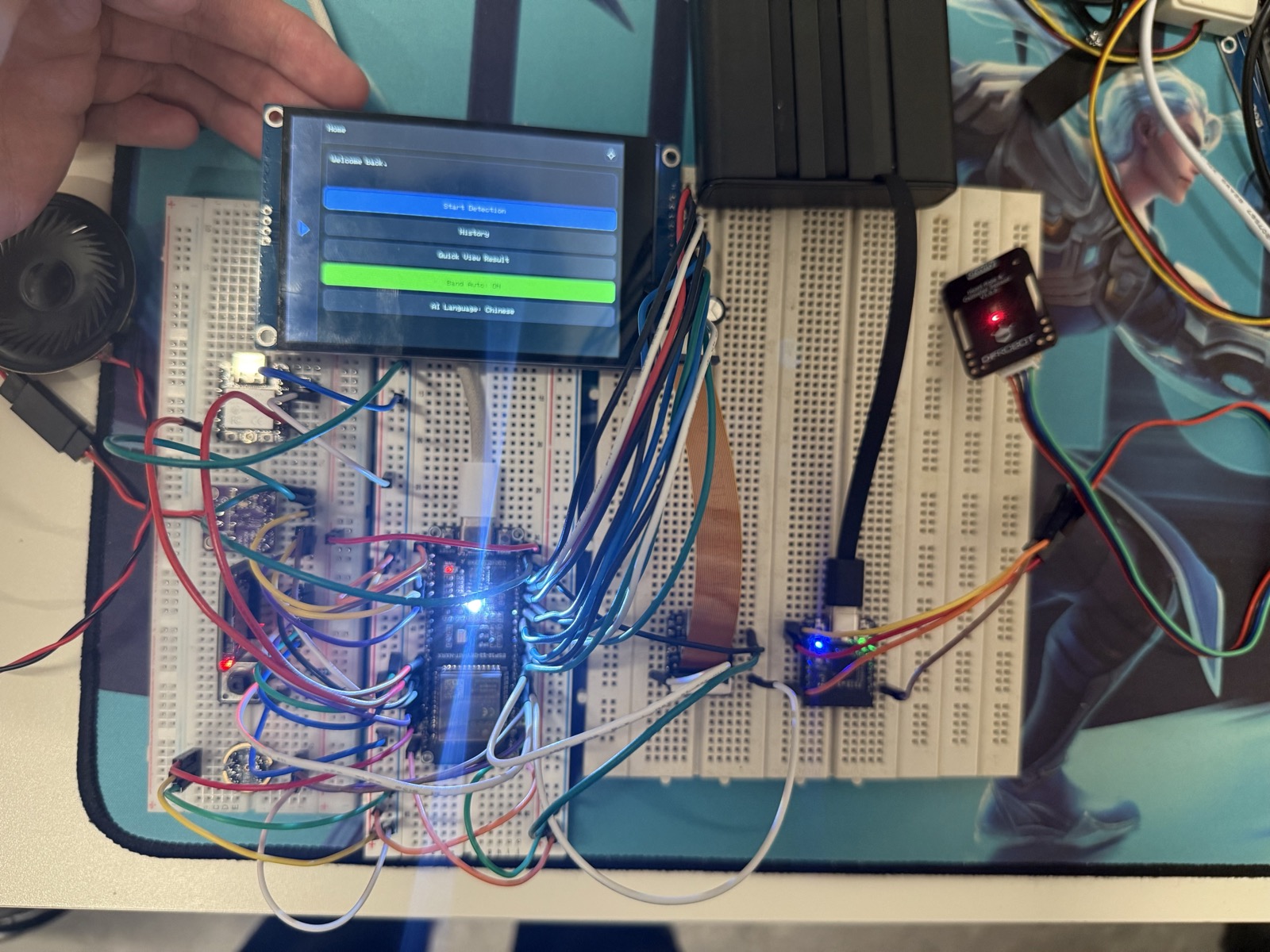
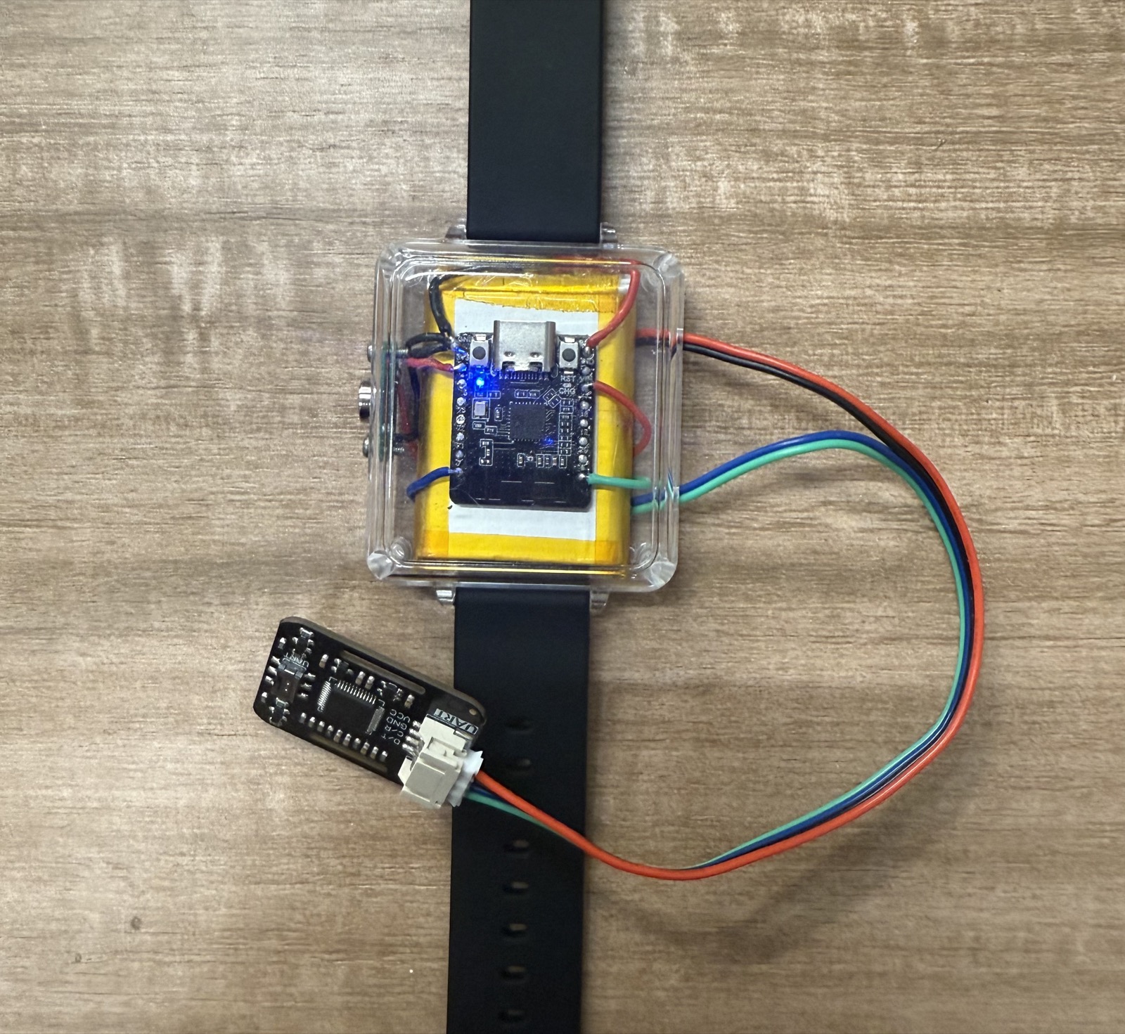
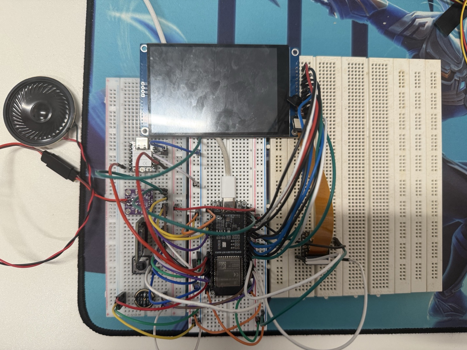
Board I designed and made
The host receiver runs on my own final-project host PCB, not on a bare commercial dev board alone. The board design, pin map, and assembly are documented in Week 16. For Week 11 I used that host PCB as the receiving node in this wearable network.
Firmware
Network firmware lives in PlatformIO project BrainFog_PIO. Downloads below are copies
of the files I flash on hardware.
| PlatformIO folder | Board | Network job |
|---|---|---|
beetle/ |
DFRobot Beetle ESP32-C6 | MAX30102 I2C read, BLE advertise + GATT notify JSON transmit. |
c3_ble_bridge/ |
XIAO ESP32-C3 | Scan/connect to BrainFog_Beetle, parse packets, forward JSON and BAND,LINK,* over UART. |
wroom/ |
ESP32-WROOM host PCB | Passive UART consumer on Serial1; screen UI and WiFi/cloud voice run here without direct BLE. |
Bring-up started with a direct WROOM BLE receiver sketch. The shipped project uses the three-folder split because BLE plus WiFi on one WROOM stalled during voice calls.
Download beetle main.cpp Download C3 bridge main.cpp Download early WROOM BLE RX test
Problems and fixes
| Problem | What I changed |
|---|---|
| Host could scan many BLE devices but connected to the wrong one | Filtered on the fixed name BrainFog_Beetle before attempting connection. |
| Connection dropped when the band moved away | Added rescan logic on disconnect. |
| Wearable reboot loop on battery power during BLE startup | Added bulk capacitance near the Beetle power input before retesting the link. |
| HR / SpO2 looked valid on the wearable serial log but not on the host | Checked service and characteristic UUIDs on both sides; the notify callback had to match the TX characteristic. |
| WROOM stalled when BLE and WiFi/cloud voice ran together | Moved BLE scan and parsing to the XIAO ESP32-C3 bridge and sent cleaned UART lines to WROOM. |