What I did in Week 11
This week I'm going to use ESP32 boards to be able to move a servo motor using networks
- Networks: A set of interconnected devices (computers, servers, cell phones) used to share data and resources, either wired or wirelessly.
- Grupal: design, build, and connect wired or wireless node(s) with network or bus addresses and local input &/or output device(s)
- Individual:send a message between two projects
Group page
Group page link
Networking & Communications
In this exercise, two ESP32-based wireless nodes were designed, built, and connected to demonstrate communication between devices using a telecommunications network. The implemented system integrates local input and output devices, as well as addressing within a WiFi network. Node A was designed as a local transmitter and actuator node. This node has a push button as a local input, two indicator LEDs, and an SG90 micro servo as a local output. When the user presses the push button, the node changes the system state between open and closed, moves the servo motor, and updates its LEDs. It also wirelessly transmits the current state to the second node. Node B was designed as a receiver node. This node connects to the same WiFi network and receives messages sent from Node A via an HTTP request. Depending on the message received, it activates its LED to remotely indicate the system state. In this way, the exercise demonstrates the integration of wireless nodes with local input, local output, and communication via a WiFi network.
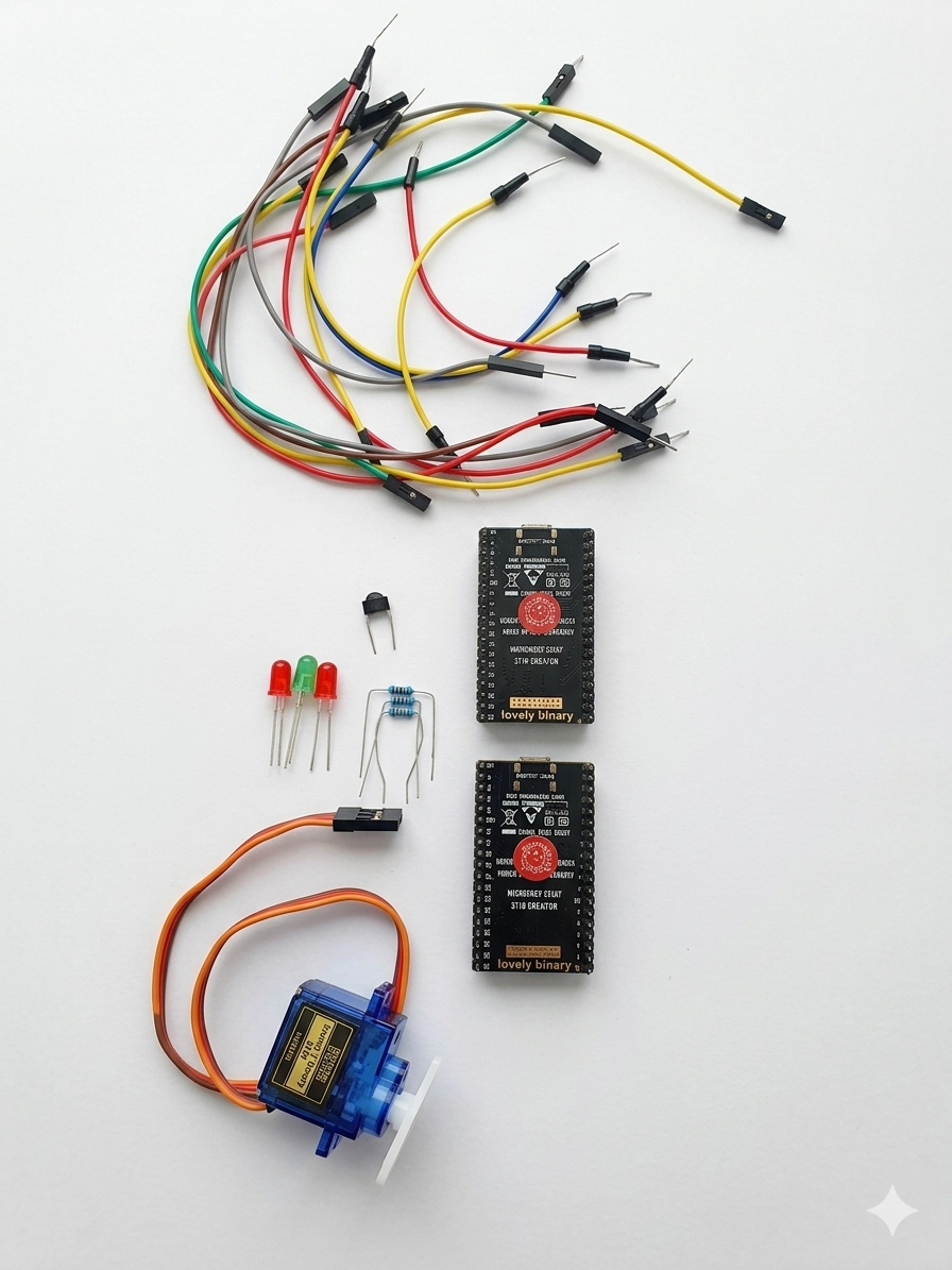
Phase 1 · General materials

Phase 2 · Node A Materials

Phase 3 · Node B Materials
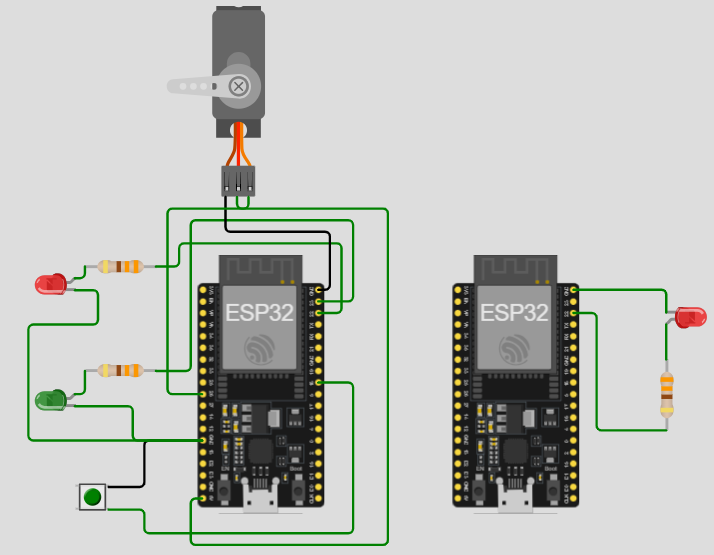
Phase 4 ·CONNECTIONS
Node A: Configured with a push button as an input, two LEDs as local indicators, and an SG90 micro servo as an actuator.
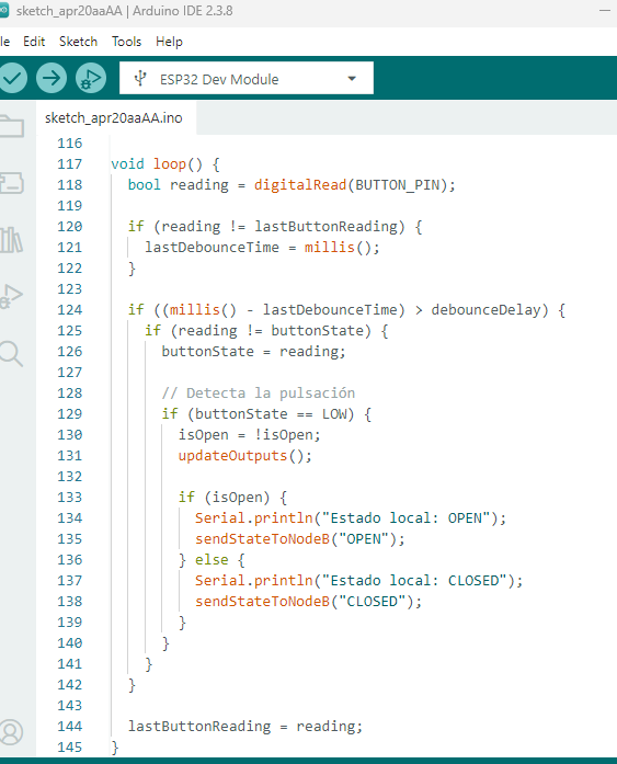
Phase 5 · Code
To access the code for node a and node b, you can download them at the bottom of the page.
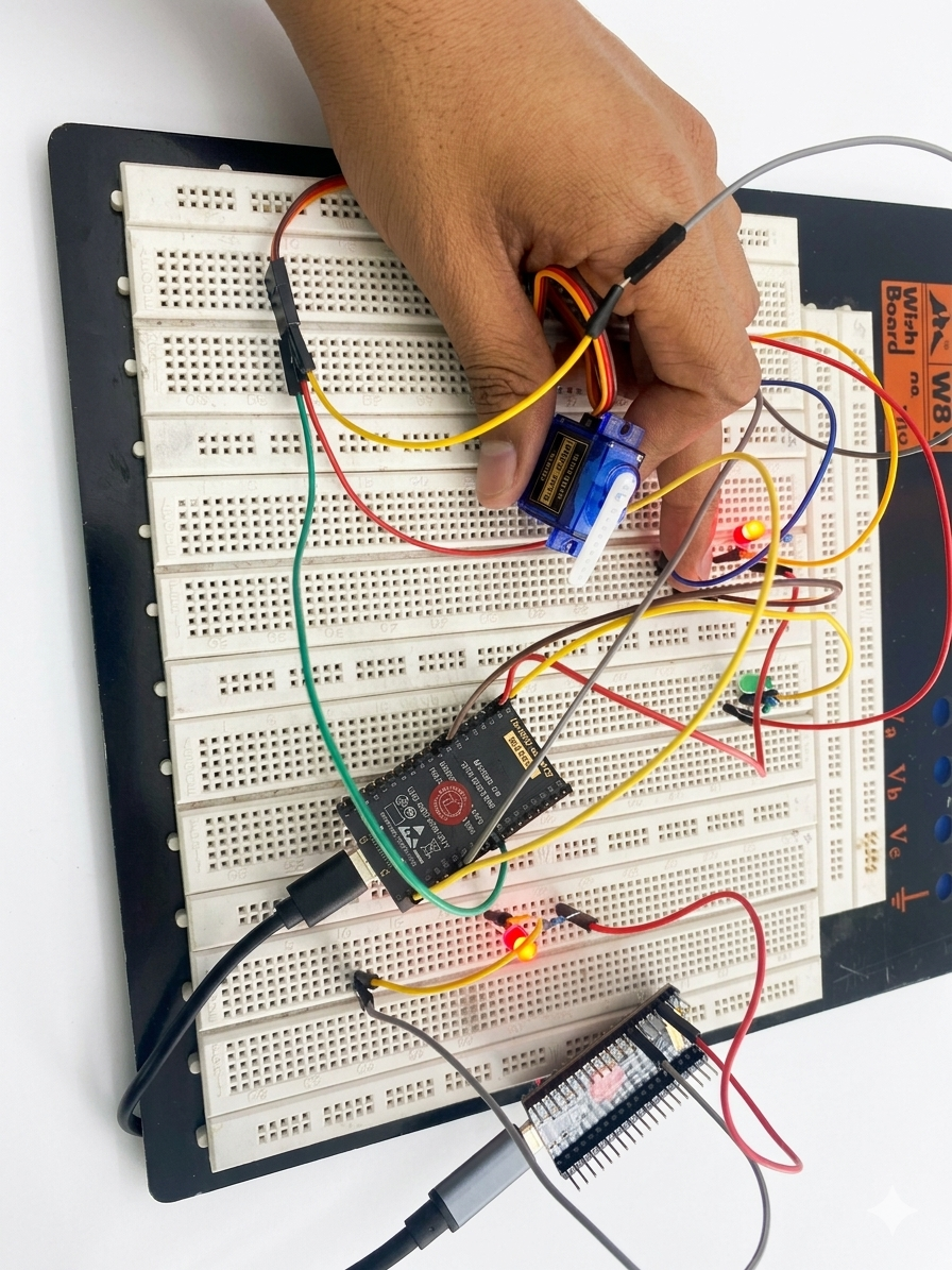
Phase 6 · DEVELOPMENT
To develop this project, the system architecture was first designed using two ESP32 nodes connected to the same Wi-Fi network. Node A was defined as the main node of the system, responsible for receiving local input via a push button, controlling a local actuator represented by the SG90 servo motor, and displaying its status using LEDs. Node B was defined as the receiver node, whose function would be to receive the message sent by Node A and visually reflect that status using its own LEDs. In the first stage, the physical connections of Node A were made, integrating the push button, the LEDs, and the SG90 servo. Subsequently, the ESP32 was programmed to connect to the wireless network, detect button presses, and alternate between two states: open and closed. For each state change, the node updates the local LEDs and moves the servo to a specific position. Next, Node B was assembled with an LED and programmed to function as an HTTP server. Once connected to the same Wi-Fi network, Node B was ready to listen for incoming requests on port 80 and process the received value parameter in the /state path. Finally, both nodes were linked by configuring Node A with Node B's local IP address. This way, every time the user presses the button on Node A, a local physical action is generated and a message is simultaneously transmitted to Node B, achieving effective communication between the two devices.
The two ESP32 boards communicated via a shared Wi-Fi network, in this case, the faculty network. Each board obtained a local IP address within the same network.
Communication was established using the HTTP over Wi-Fi protocol. Node B was configured as a web server on port 80, while Node A acted as the client. When the user pressed the button on Node A, it sent an HTTP GET request to Node B's IP address with one of the following messages:
The request sent had the form:
When Node B received the request, it read the value parameter, updated its internal state, and activated the corresponding LED. In this way, communication between nodes was not carried out by direct electrical connection, but by a WiFi-based telecommunications network. A system consisting of two ESP32 wireless nodes connected to the same Wi-Fi network was successfully built and programmed. Node A responded correctly to the local push-button input, toggling the system state between open and closed. As a local response, the SG90 servo motor changed position, and the LEDs on Node A visually indicated the current state. Additionally, Node A correctly sent the state to Node B using the latter's local IP address. Node B received the OPEN and CLOSED messages and illuminated its LEDs accordingly, confirming successful communication between the two devices. The system allowed for practical verification of the integration of local input, local output, and data transmission over a wireless network.
Conclusions
The experiment demonstrated that two ESP32 nodes can communicate effectively over a local Wi-Fi network using IP addressing and HTTP requests, thus fulfilling the requirement for connection via a telecommunications network.
The integration of local input, local output, and remote communication enabled the development of a functional and educational system in which Node A performs a real physical action and Node B remotely reflects the received state, demonstrating the coordinated operation between the two nodes.
← Main Page