What I did in Week 08
This week covered computer-controlled machining from safety and machine characterization through CAM software setup, toolpath generation, G-code output, real cutting, and final assembly.
- PCB methods: reviewed dead bug, etching, and machining approaches to PCB fabrication.
- Machining workflow: practiced tool selection, fixturing, zeroing, and post-processing steps like deburring and cleaning.
- Group: • characterize the design rules for your in-house PCB production process • submit a PCB design to a board house
- Individual: • make and test an embedded microcontroller system that you designed • extra credit: make it with another process
Group page
Group page link
Process

Phase 1 ·
During electronic design week we already completed the design of our circuit board that we are going to produce, so in the KiCad software we are going to save our file with the tracks already generated.

Phase 2 ·
We save the file in gerbers format; to do this we go to File - Manufacturing Output - Gerbers

Phase 3 ·
We select the folder where we want to save the Gerber files and click on Generate to save the files

Phase 4 ·
We generate the drilling files.
Phase 5 ·
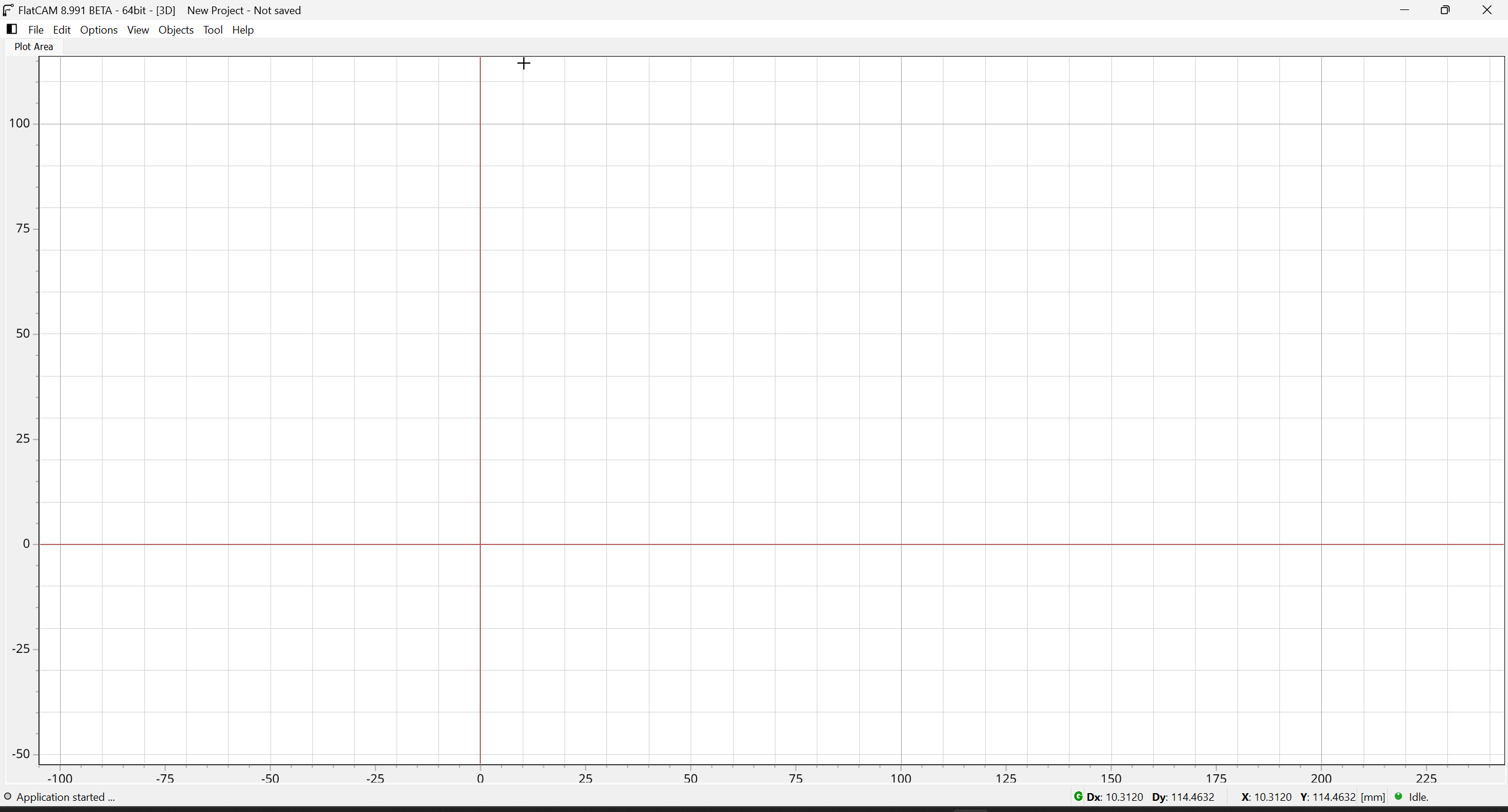
We open the Flatcam software, which allows us to generate the g-code to machine the electronic boards.

Phase 6 ·
We open the Gerber files for the tracks and Excellon to make the holes for the components that require them. In this case, for the tracks, what I need to machine are on the front layer of the copper face.

Phase 7 ·
This is how the files we are going to machine look; the tracks are in green and the drilled holes are in red.
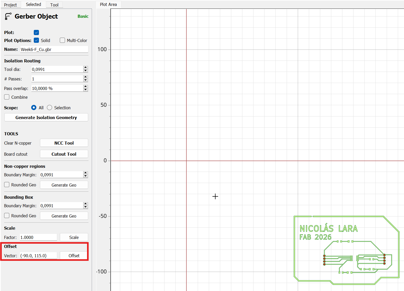
Phase 8 ·
We need to place the tracks near the coordinate center so the machine doesn't malfunction at its limits. To do this, in the offset field, we enter the coordinates where we want the tracks to be placed.

Phase 9 ·
We access the NCC tool option to configure the milling cutter

Phase 10 ·
We configure the tool we are going to use; in my case I will use a 1/64 milling cutter.

Phase 11 ·
When generating the geometry, we can see the red line that indicates where the milling cutter will rough out.

Phase 12 ·
We generate the CNC code and then save the file in a folder we know.

Phase 13 ·
We also configured it to drill the holes; in my case, I'm going to use a 1/32 milling cutter. We created the holes and saved the file for machining.

Phase 14 ·
To machine my plate I will use an SRM-20 machine and the software that controls this machine is Vpanel.
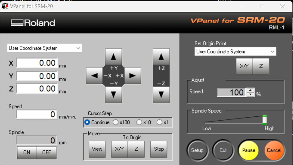
Phase 15 ·
We connect the computer to the machine and wax our machine according to the location of the copper plate that we are going to machine.
Phase 16 ·
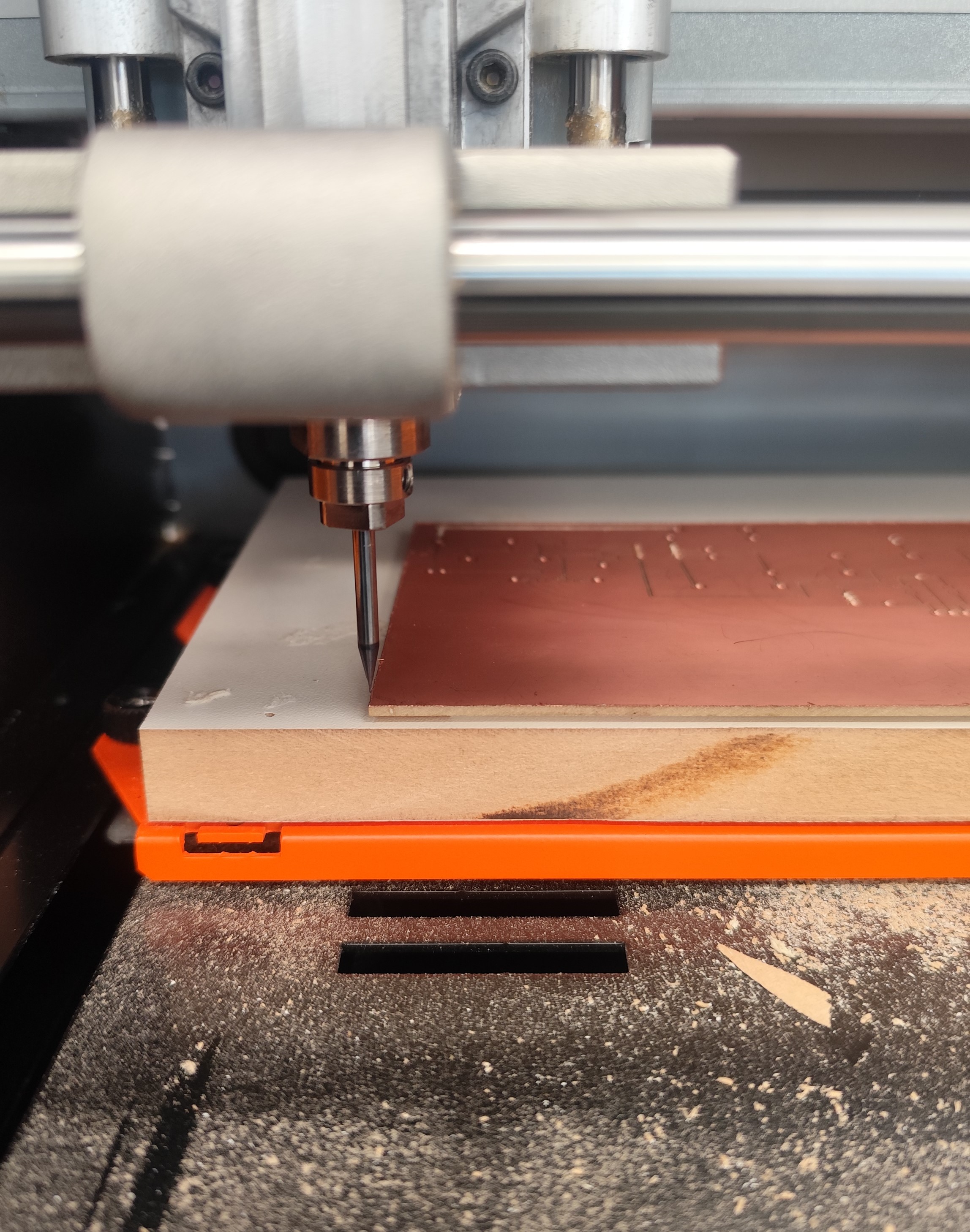
We place the plate in the machine taking into account what our zero point is.

Phase 17 ·
We select the file we are going to machine, configure the speeds, and run the program.
Phase 18 ·
We wait for the code that will create the electronic tracks to run, then we change the milling cutter for the holes and cutting of the board.
Phase 19 ·
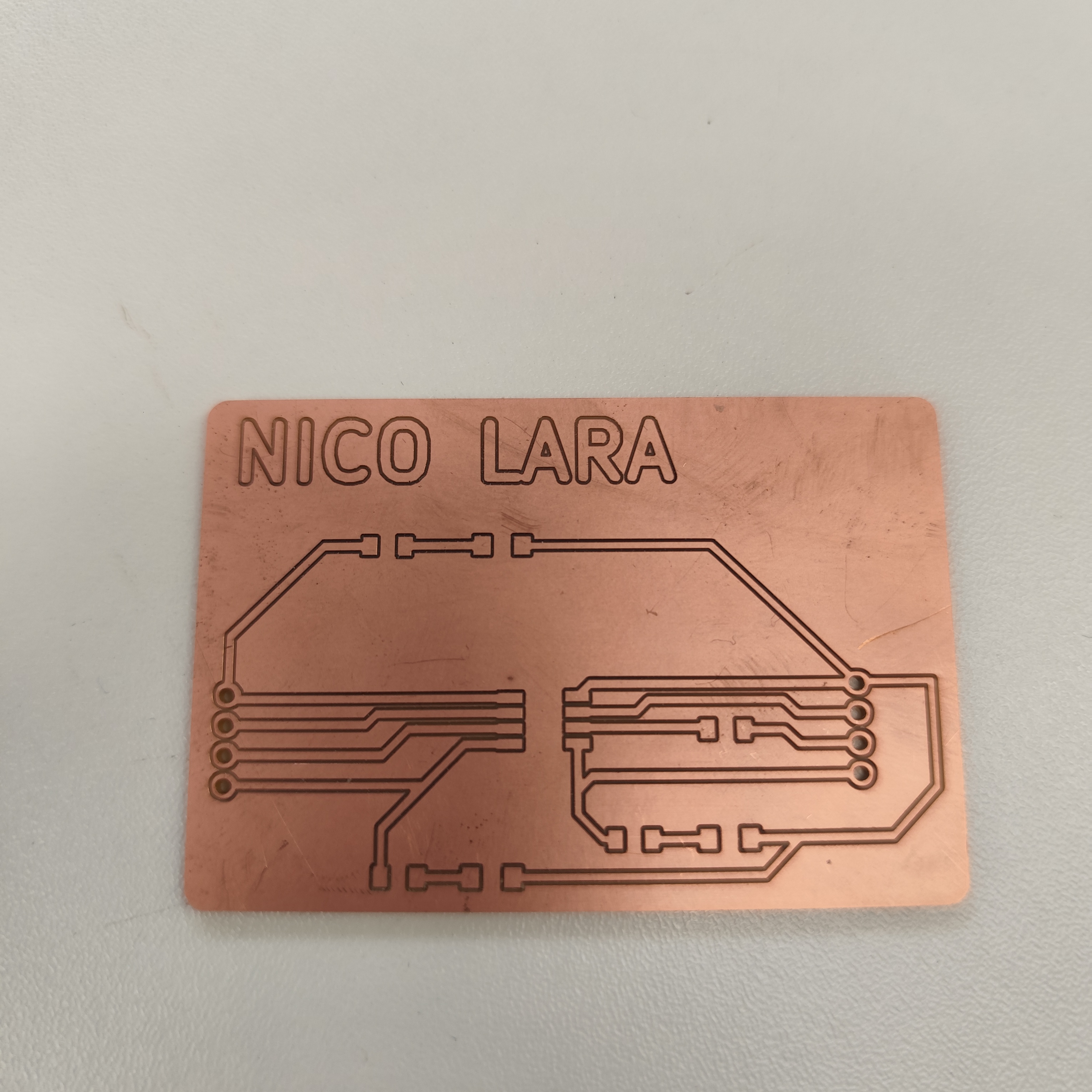
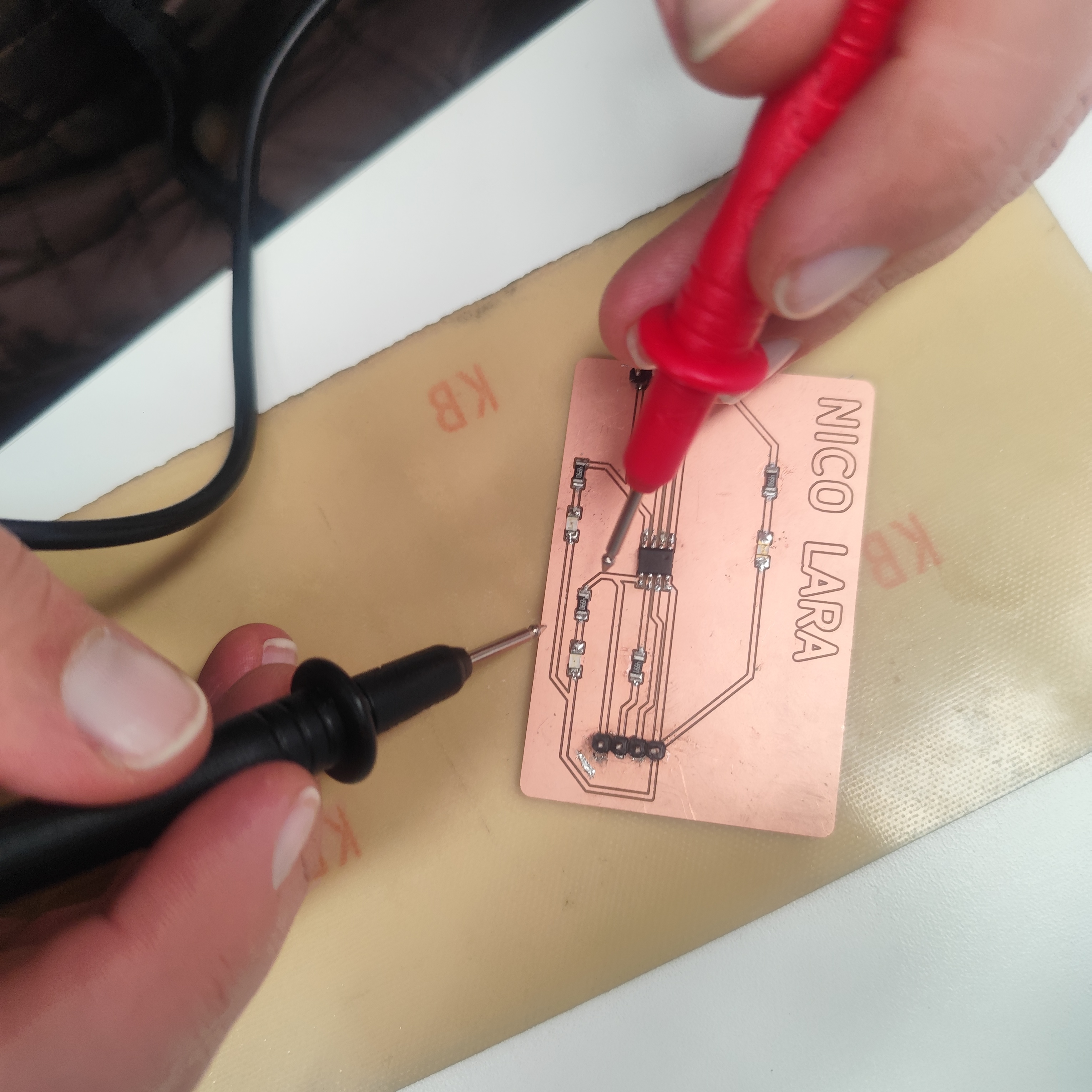
Finally, we obtain the electronic board, which we must check with a multimeter if there is continuity between the traces.
Phase 20 ·
We soldered the electronic components using a soldering iron, solder, and soldering paste. we obtain the electronic board, which we must check with a multimeter if there is continuity between the traces. Finally, we obtain the electronic board, which we must check with a multimeter if there is continuity between the traces. Since I had not soldered SMD components, it took me a little while to solder the components.
Phase 21·
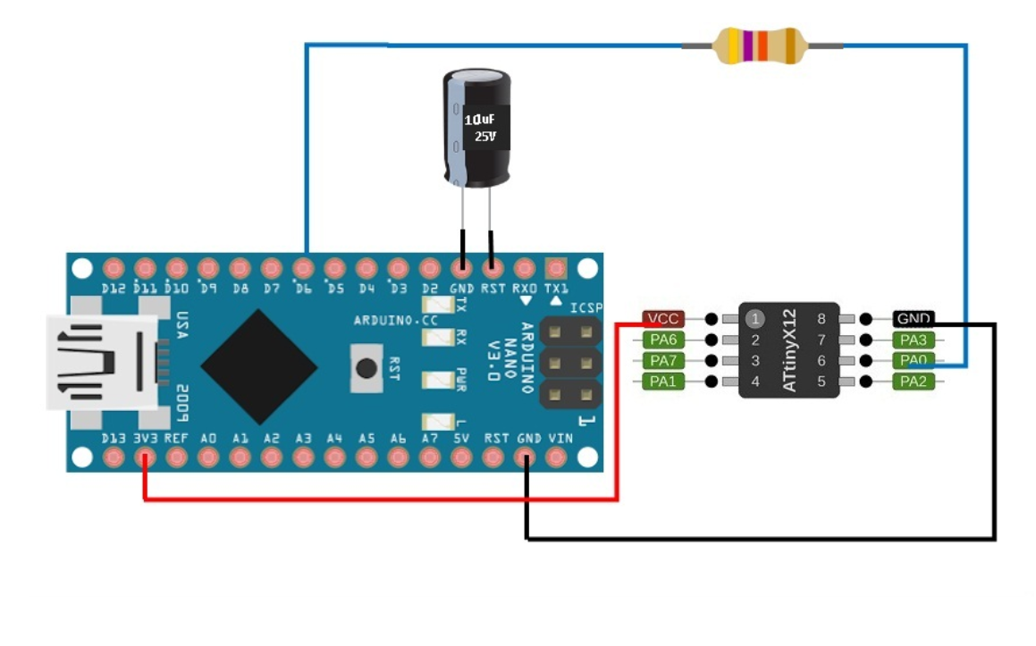
To upload programs to the microcontroller, you need to add a URL ("http://drazzy.com/package_drazzy.com_index.json") to add other boards. This can be done in File --> Preferences --> Manager. You also need to install the megaTinyCore library. Then, upload the code from https://github.com/SpenceKonde/jtag2updi to your Arduino Nano and finally connect your board to the Arduino to upload the programs.

Phase 22
I configure the Arduino IDE to upload the program to the board I made.
Phase 23 ·
I configure the Arduino IDE to upload the program to the board I made.
Conclusions
This week I gained a comprehensive understanding of the electronics manufacturing process, from PCB fabrication to circuit assembly and testing. I learned how to prepare files for milling, properly configure the CNC machine, and perform more precise soldering of electronic components. I also grasped the importance of calibration and parameter control during the manufacturing process, as even small errors in alignment, depth of cut, or connections can completely affect the board's functionality. The debugging and testing phase was crucial for identifying and correcting errors.
← Main Page