What I did in Week 07
This week covered computer-controlled machining from safety and machine characterization through CAM software setup, toolpath generation, G-code output, real cutting, and final assembly.
- CNC: Computer Numerical Control
- G code: standard programming language used to control Computer Numerical Control (CNC) machines
- Group: do your lab's safety training. Test runout, alignment, fixturing, speeds, feeds, materials, and toolpaths for your machine
- Individual: make (design+mill+assemble) something big (~meter-scale)
- Extra credit: don't use fasteners or glue.
Group page
Group page link
Design, assembly and simulation
For this activity, a base module was designed so that, using a single piece, different shapes could be formed as modules were assembled using interlocking slots. This type of modular design allows for the creation of diverse structures depending on how the pieces are connected. The design was developed using SolidWorks software, which was used for both modeling the piece and the final assembly of the modules.
Design
Phase 1 ·
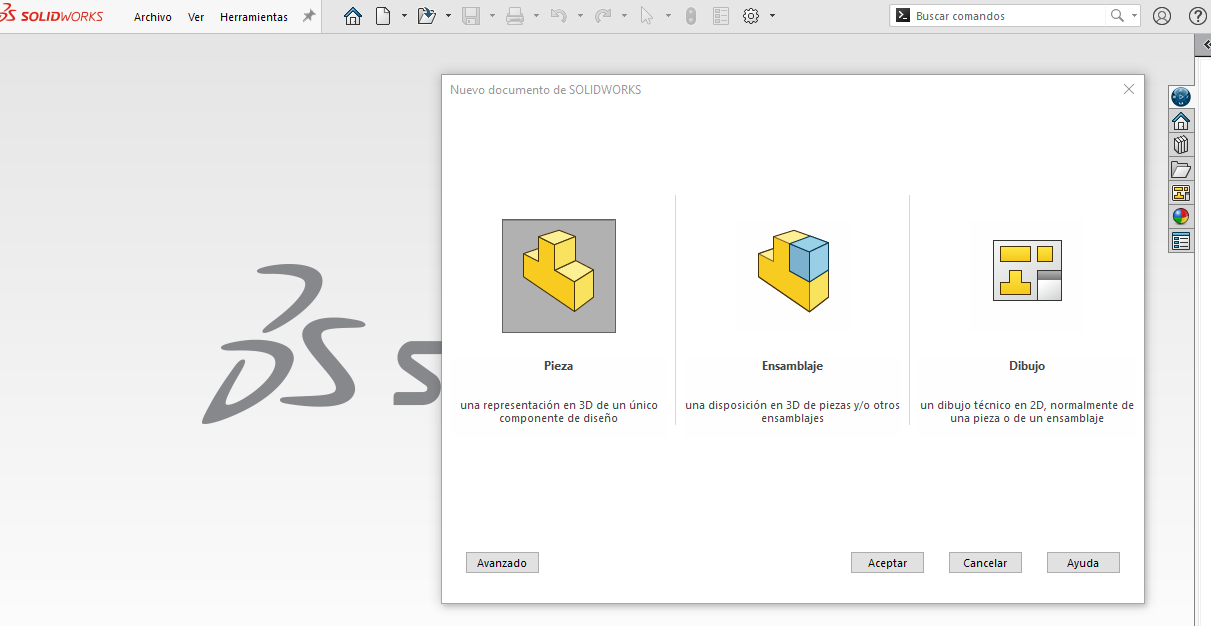
First, we enter the SolidWorks program, select the Part option, and click OK to begin designing the module.
Phase 2 ·
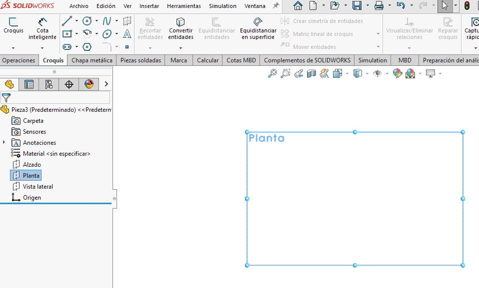
We selected the top plane and began to create the basic sketch of the module.
Phase 3 ·
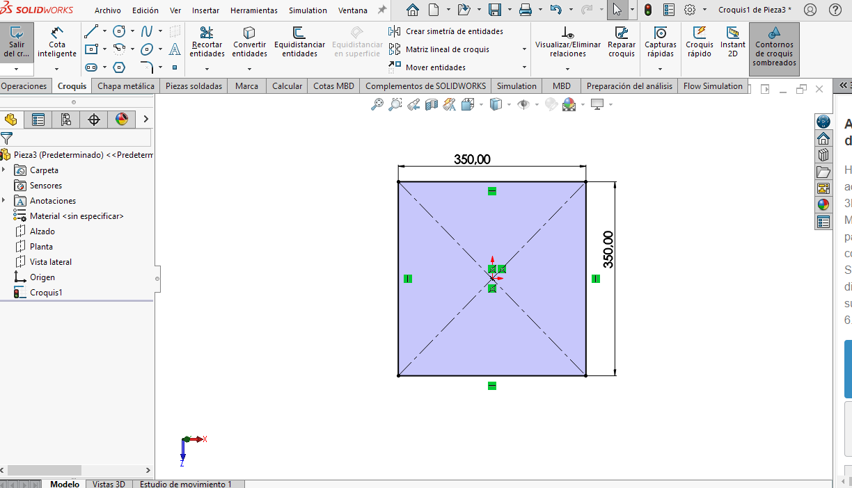
Within the Sketch tab, select the Line tool and draw the base geometry. In this case, the module is a square with sides of 350 mm. Once drawn, add the required dimensions and then go to the Features tab.
Phase 4 ·
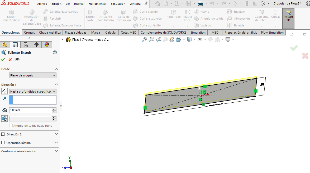
To give thickness to the module we used the Extruded Boss/Base option and assigned a thickness of 6 mm, since the material to be used is 6 mm MDP.
Phase 5 ·
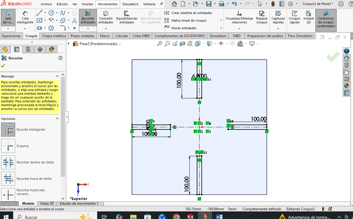
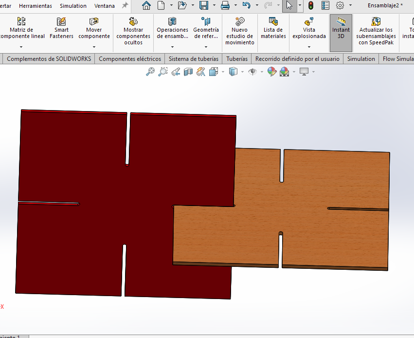
Once the required thickness is determined, we begin to draw the grooves and then make the cut.
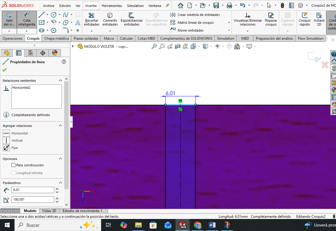
Phase 6 ·
After drawing the slots, the unnecessary lines are trimmed. A tolerance of 0.1 mm is allowed to facilitate assembly and disassembly of the modules. For this reason, the slots are 6.1 mm wide (slightly greater than the material thickness) and 100 mm long.
Phase 7 ·
To generate the grooves, we select the Extruded Cut option in the operations tab and select the previously drawn entities to perform the material cut.
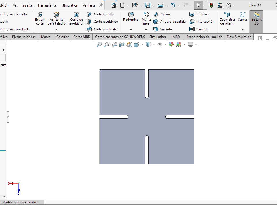
Phase 8 ·
Once the cut is made, the module is ready with the necessary slots to allow its assembly with other identical pieces.
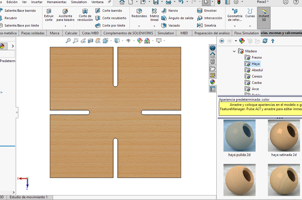
Phase 9 ·
As a final step in the design of the piece, a wood appearance is assigned from the Appearances tab, selecting a beech-type finish, to simulate the actual material of the module.
Assembly
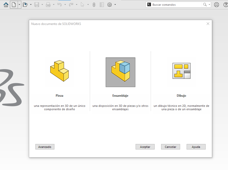
Phase 10 ·
To perform the assembly, go to File > New and select the Assembly option.
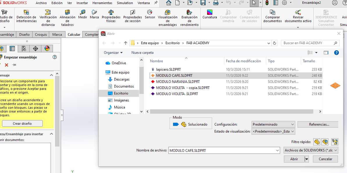
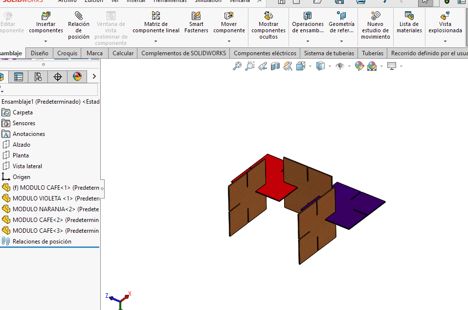
Phase 11 ·
The option to insert components appears automatically. We select the designed module and click OK. For this project, three modules of different colors were used, although they all maintain the same dimensions.
Phase 12 ·
WTo continue adding modules, we use the Insert components option and select the modules according to the desired color.
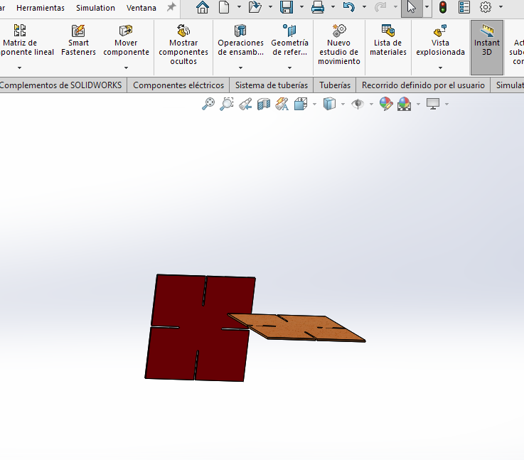
Phase 13 ·
To assemble the modules correctly, we use Position Relations. These are applied by selecting faces, lines, or vertices of one module and relating them to the slots of another module to fix its position.
Phase 14 ·
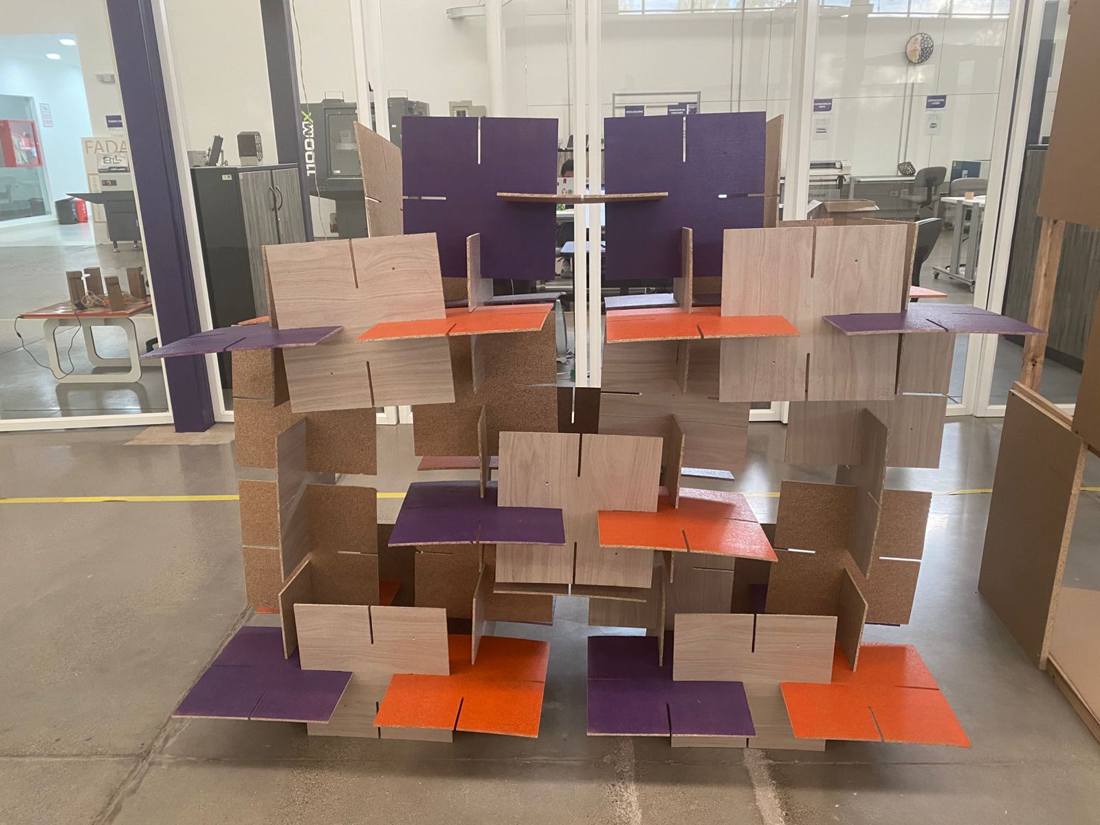
Because the design is modular, the pieces can be placed in different orientations, allowing for the creation of various structural configurations with the same type of piece.
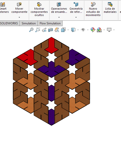
Phase 15 ·
Finally, after defining the desired configuration, the final assembly is obtained. In this case, a structure was formed that repeats its pattern.
Simulation
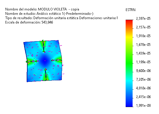
To evaluate the structural behavior of the 6 mm thick MDP module, a static analysis was performed using the finite element method with SolidWorks Simulation. This study allowed for the analysis of the stress, displacement, and strain distribution generated by applying a load representative of the lighting system's weight. The results show that the maximum Von Mises stress was 0.091 MPa, a value considerably lower than the material's yield strength (12 MPa), demonstrating that the module operates within safe conditions. Likewise, the displacement analysis revealed a maximum deformation of 0.064 mm, indicating adequate structural stiffness, while the maximum strain of 2.397 × 10⁻⁵ confirms that the material remains within the elastic range, guaranteeing the structural integrity of the proposed design.
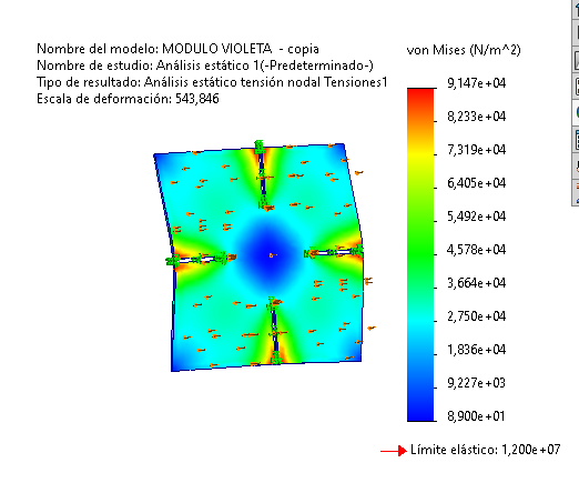
Phase 16 ·
The Von Mises stress analysis shows that the maximum stress obtained was 0.091 MPa, a value much lower than the elastic limit of the MDP (12 MPa), which indicates that the module design is structurally safe under the applied load.
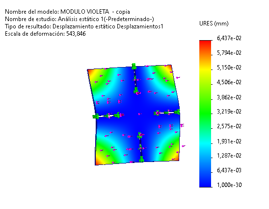
Phase 17 ·
The displacement analysis shows a maximum deformation of 0.064 mm, indicating high structural stiffness of the module under the applied load. This result confirms that the design maintains its dimensional stability during operation.
Phase 18 ·
The unit strain analysis shows a maximum value of 2.397×10⁻⁵, indicating that the material works within an elastic regime with minimal deformations, confirming the structural integrity of the module.
MACHINING
Step 1 ·
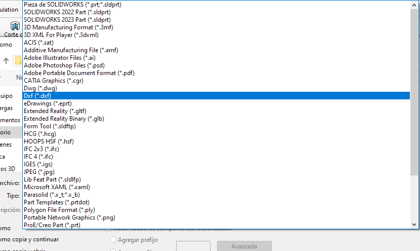
To export the design in DXF format (a format compatible with the CNC machine), you must select the "Save as" option and choose the .dxf file type, which will then allow you to import the design into the machining software.
Phase 2 ·
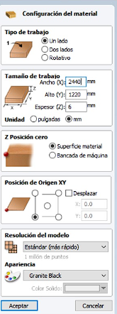
The Vectric software allows you to read the file in DXF format. This program is used to configure the cutting tool, speeds, and machining paths. The configuration of the workpiece to be machined is performed, establishing the dimensions on the X and Y axes, the material thickness, and the workpiece zero position. Then, the file is imported.

Phase 3 ·
In the Vectric program, we select the operation we want to perform, in this case profiling, we configure the tool and speeds and simulate.
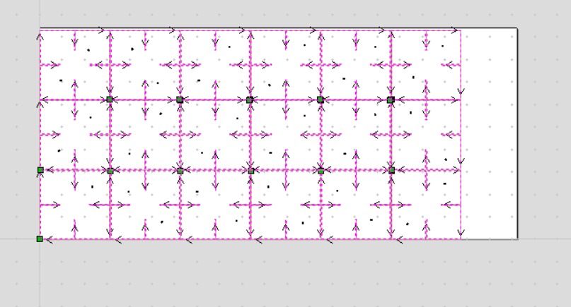
Phase 4 ·
The program allows you to visualize the path along which the milling cutter will move.
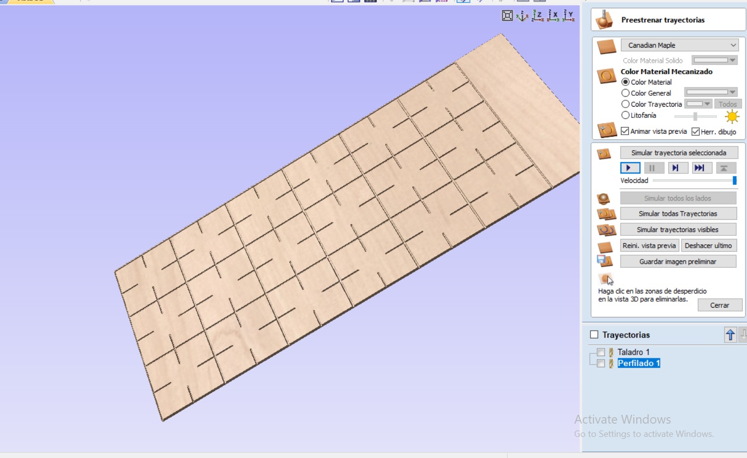
Phase 5 ·
You can also run a simulation to see how the board will look after machining.

Phase 6 ·
In the program, once all the configurations are made, the file is saved with the .sbp extension, which is the format compatible with the ShopBot machine.
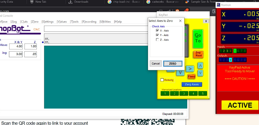
Phase 7 ·
For machining we will use the Shotbot software. The tip of the milling cutter must be taken to the point closest to the workpiece zero according to the established reference and then the zero must be set on the X and Y axes.
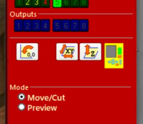
Phase 8 ·
The yellow symbol allows you to move the tool along different axes and set the machine zero. The Z-axis icon allows you to calibrate this axis using a gauge block.

Phase 9 ·
To import the file with the machining code, click on the Cut Part option and select the file to be machined.

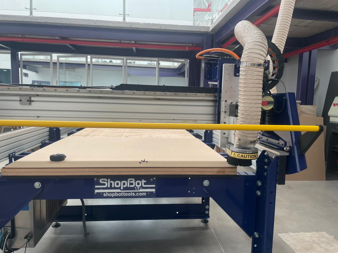
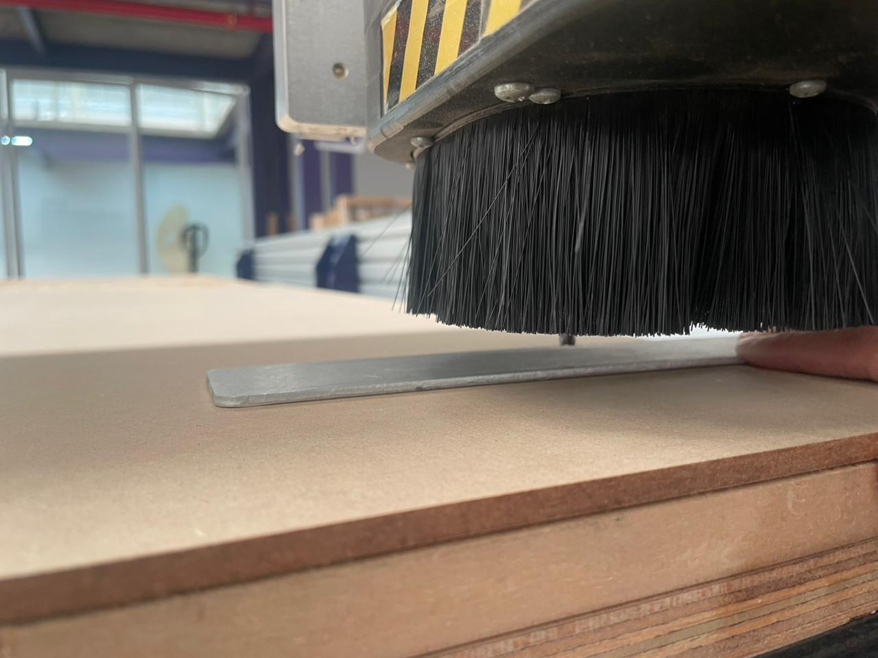
Phase 10 ·
Finally, the machining process begins and, once finished, the proposed figure is assembled with the modules obtained.
Conclusions
This week you will learn the computer-controlled machining process and how to transform digital designs into large-scale physical objects using CNC machines. You will also learn how to prepare toolpaths, configure machining parameters, and operate CNC equipment safely to achieve precise cuts and assemblies. It was essential to understand how material properties, tool selection, depth of cut, and machining strategies directly affect the quality and accuracy of the final result. I will also improve my skills in CAM software, machine setup, and production planning, while learning the importance of calibration and safety during machining processes.
← Main Page