What I did in Week 05
This week's group assignment focused on testing and characterizing the design rules of our in-house 3D printer using a standard all-in-one benchmark. The process included two full print cycles, error diagnosis, and parameter adjustment.
- Printer characterization: tested support, scale, overhang, hole, diameter, and bridging performance.
- Failure analysis: identified overhang and print clarity issues and traced them to speed and nozzle settings.
- Group: Test the design rules for your 3D printer.
- Individual: Design, document, and 3D print an object that could not be made subtractively (small, few cm3, limited by printer time). 3D scan an object (and optionally print it).
Group page
Group page link
3D print
In this activity we will carry out the entire process to be able to 3D print, in my case I used a Bambu x1c printer which is the one we have in the laboratory.
Step 1 ·
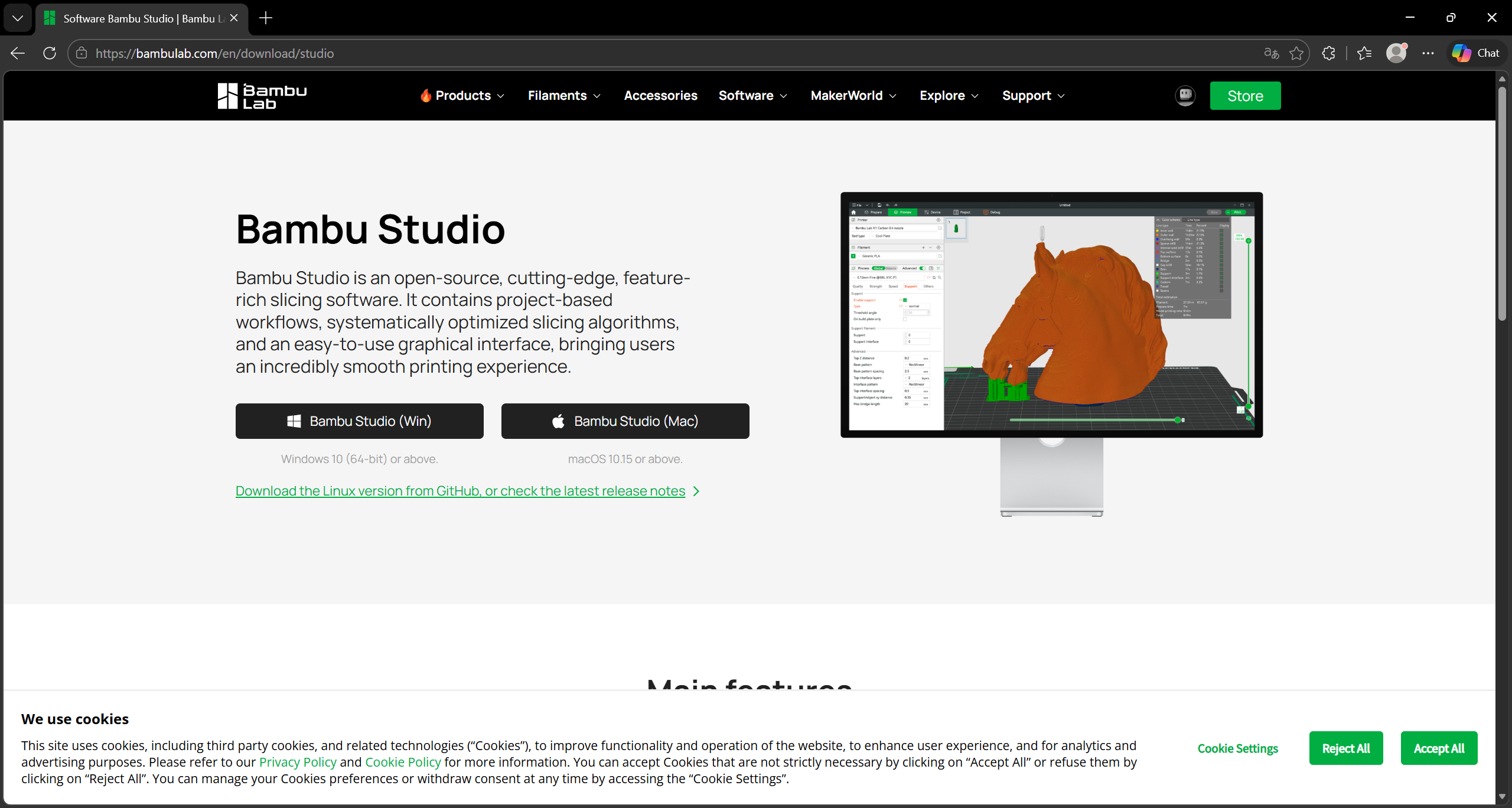
To print, download the Bambu Studio application from the following link: https://bambulab.com/en/download/studio
Step 2 ·
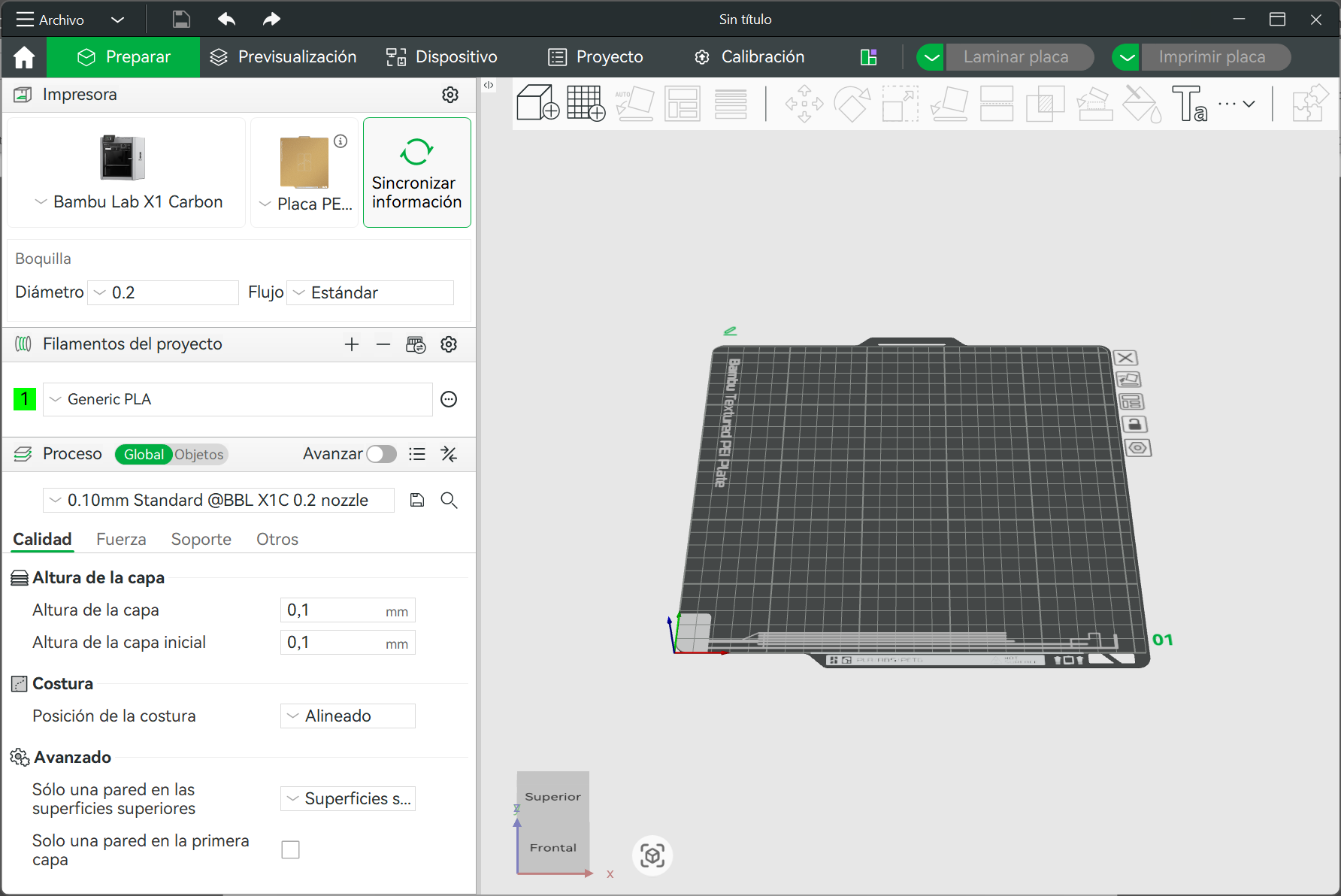
We open the program and select the printer we are going to use and the dimensions of the heat press, then next to the house icon, we select the PREPARE option
Step 3 ·
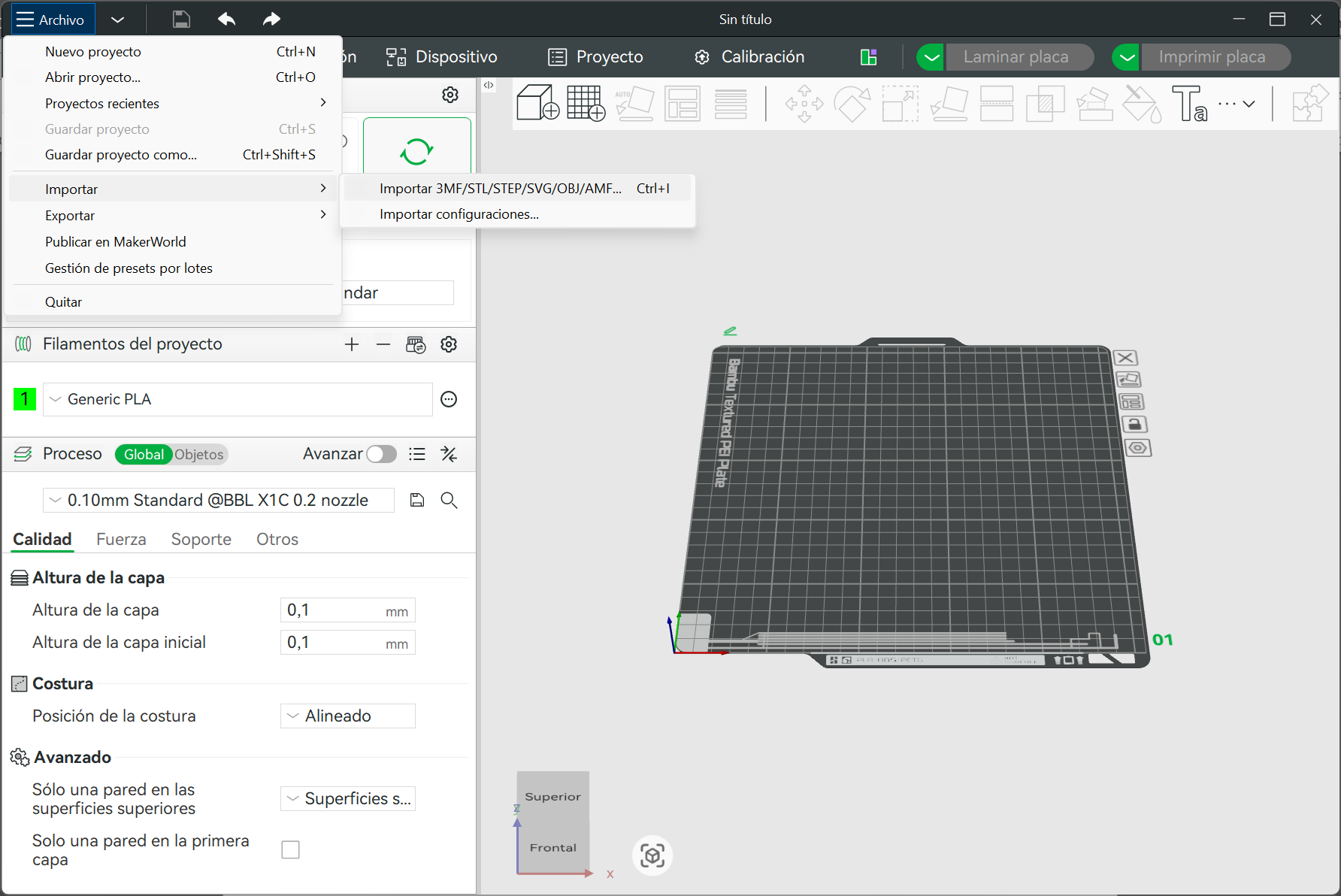
In that space we select the FILE option, and then import the model saved in STL format.
Step 4 ·
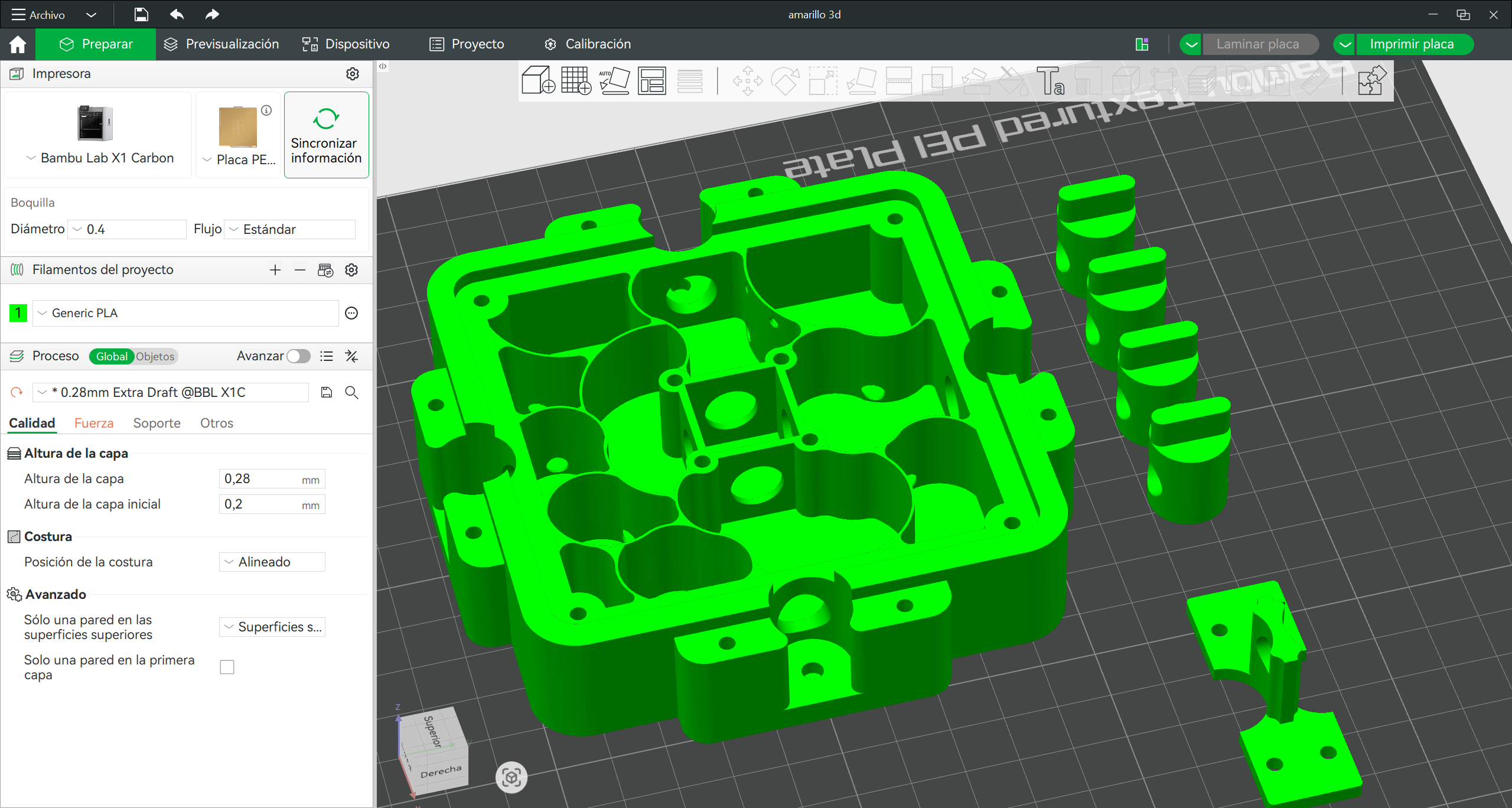
Once the pieces have been selected, we arrange them on the plate in a way that doesn't create too many supports.
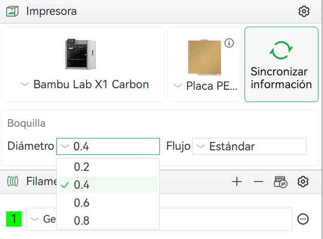
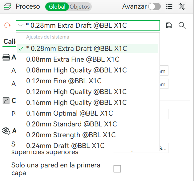
Step 5 ·
We select the nozzle that we have installed on the 3D printer and the layer height depends on the quality of the part to be printed; in this case we use 0.28mm since it does not have much detail on the Z axis.
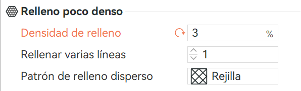
Step 6 ·
We applied a low infill density to the part since it will be used without movement or compression, plus a rectilinear grid to compensate for the low density.
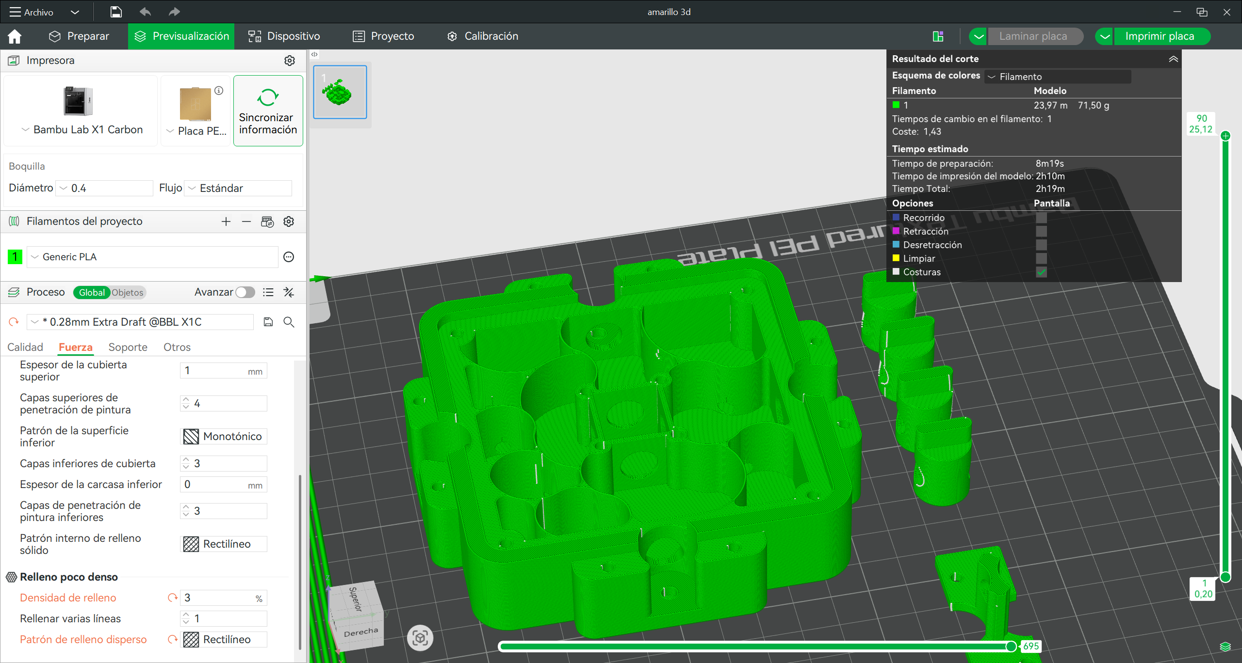
Step 7 ·
Once those parameters are set, we click on Laminate Plate and we will see a preview of how the printed image will look.
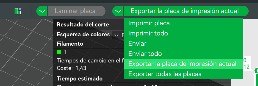
Step 8 ·
Ready to print, we open the tab that says “print plate” and select the option to “Export the current printing plate”
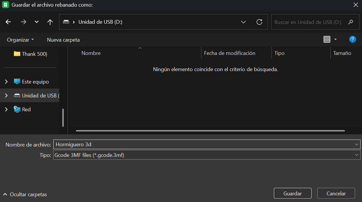
Step 9 ·
We save it to an SD card to later insert into the printer.
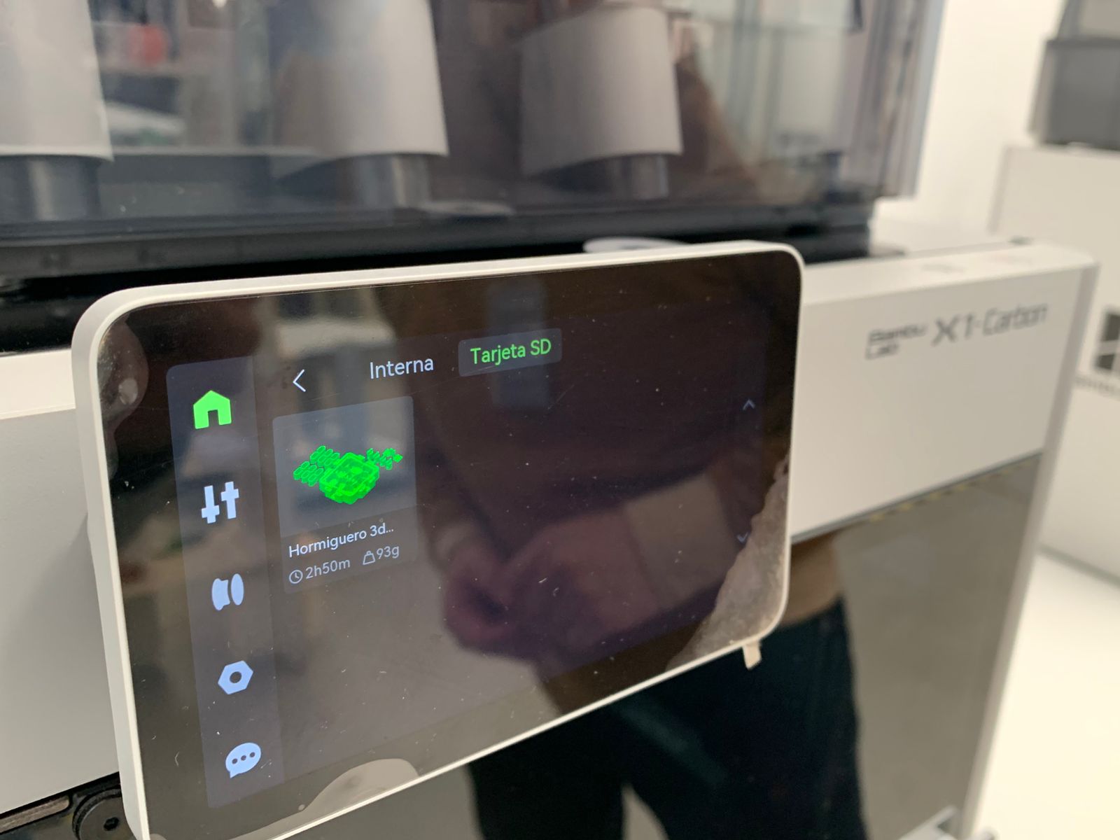
Step 10 ·
Once saved, we insert it into the printer and select the document.
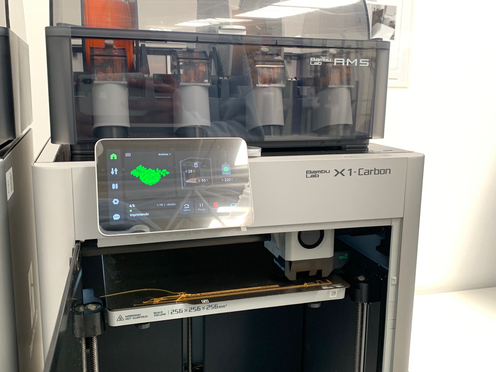
Step 11 ·
Once shipped, it begins to calibrate automatically, controlling the bed level and the temperatures of the printheads, the iron, and the environment.
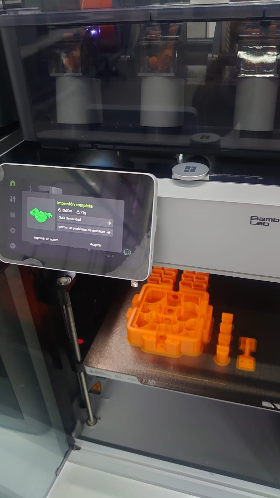
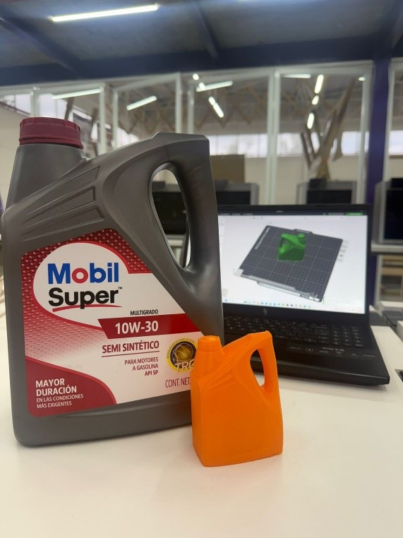
Step 12 ·
Once the 3D printing is complete, we obtain the result in this way.
3D scan
3D scanning has several applications, one of which is reverse engineering. Another application, which I will demonstrate, is scanning an object or person, and here I will show all the steps to achieve this.
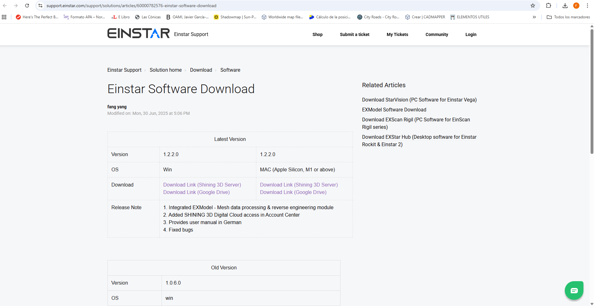
Step 1 ·
To begin, download the EINSTAR program from the official support link: https://support.einstar.com/support/solutions/articles/60000782576-einstar-software-download
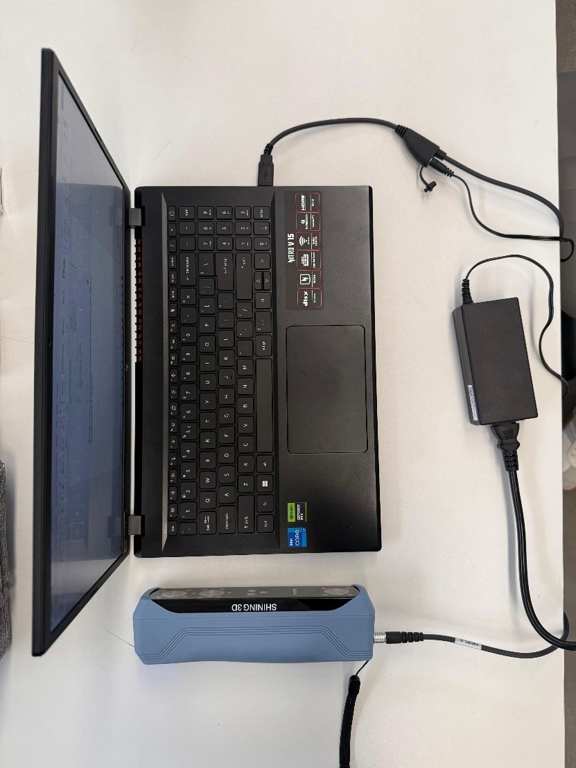
Step 2 ·
While the program is downloading, we connect the scanner to the power supply and connect the USB cable to the computer.
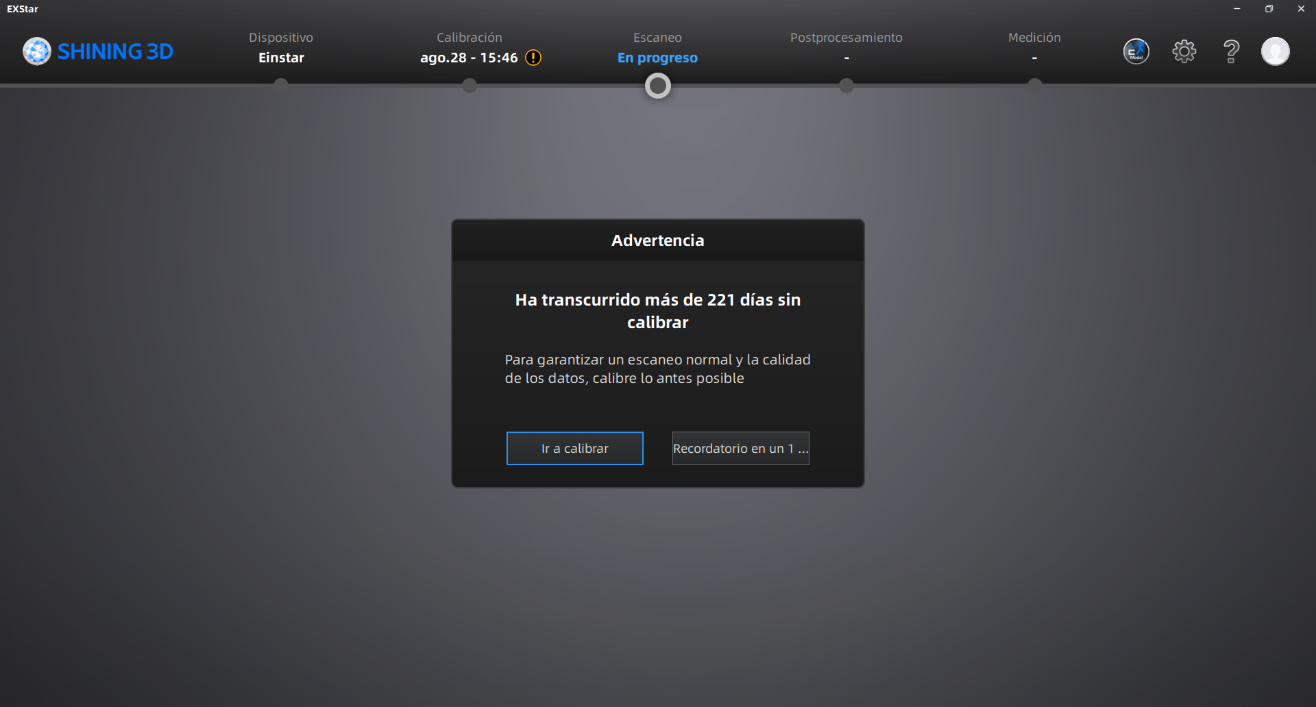
Step 3 ·
Once the scanner is connected to the computer, open the downloaded application. After logging in, proceed to calibrate the scanner.
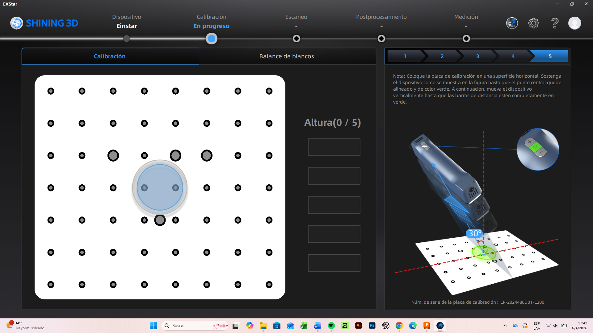
Step 4 ·
It is essential to follow the calibration instructions and visual guides to ensure an optimal process.
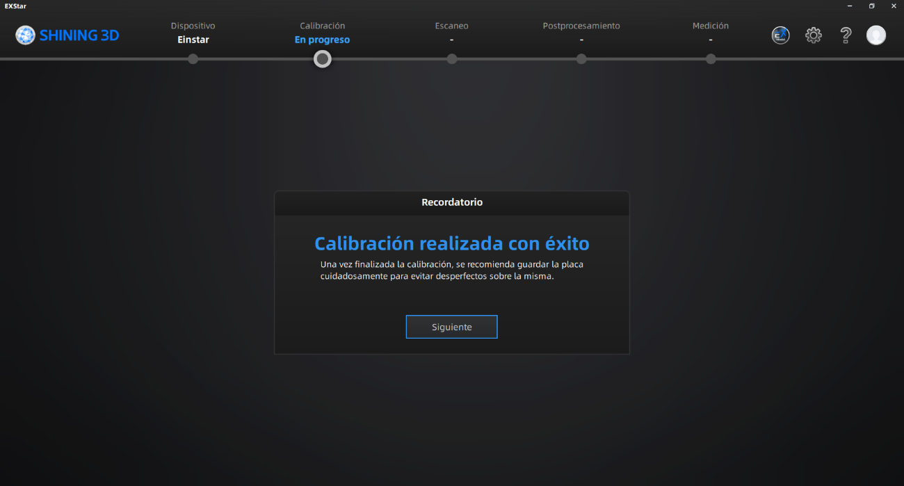
Step 5 ·
After this message, we have calibrated the first part.
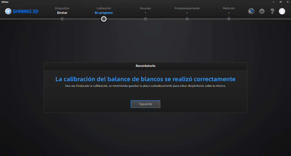
Step 6 ·
After that, we continued with the white balance, following all the steps correctly.
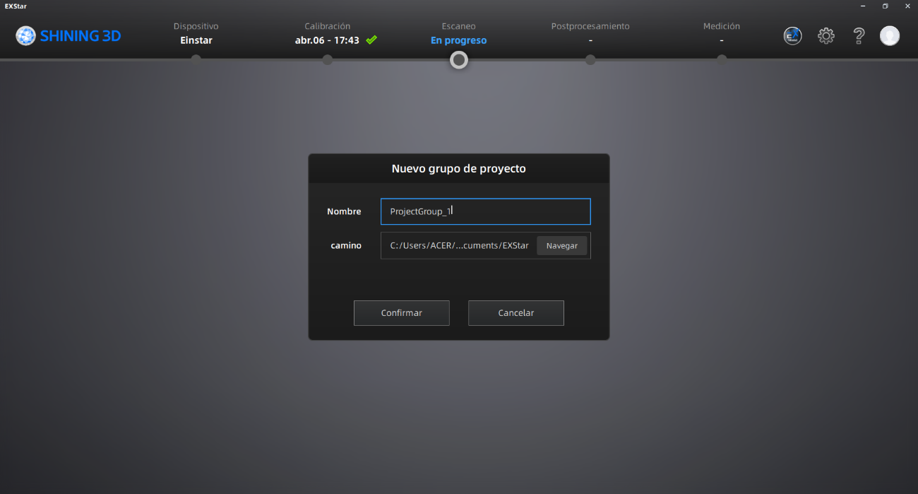
Step 7 ·
Once these steps are completed, we create a New Project Group, assigning it a name and a specific save path.
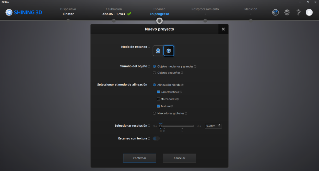
Step 8 ·
We adjusted the system parameters according to the job requirements; in this case, the object to be digitized is a plastic bottle. A resolution of 0.5 mm was avoided, as the definition was insufficient to capture the necessary details. Therefore, a resolution of 0.2 mm was set.
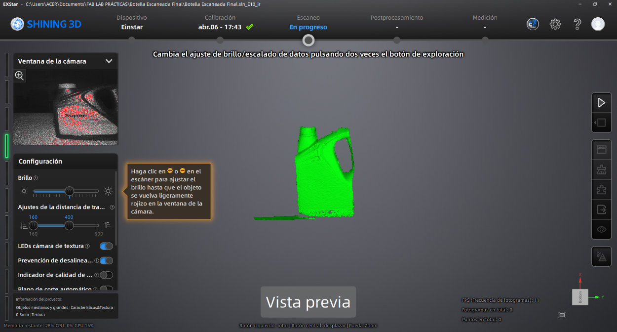
Step 9 ·
With the project set up, we activate the preview with the start button to inspect the lighting using the Brightness control, as well as verify the stability and position of the bottle.
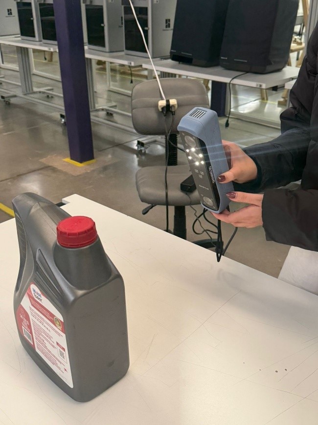
Step 10 ·
After validating the configuration in the preview, we start data capture by pressing the Play button on the scanner again.
Step 11 ·
Once the scan is complete and we have verified that the shape of the bottle has been fully captured, we pause the operation with the Play button.
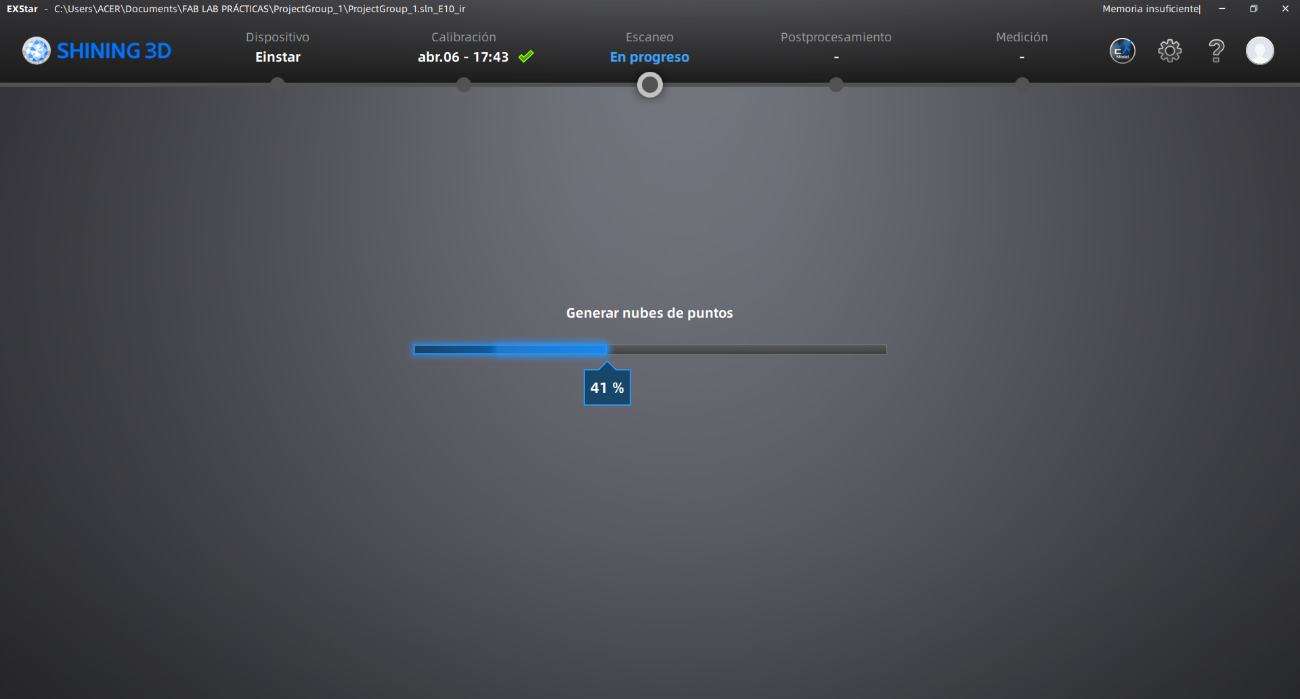
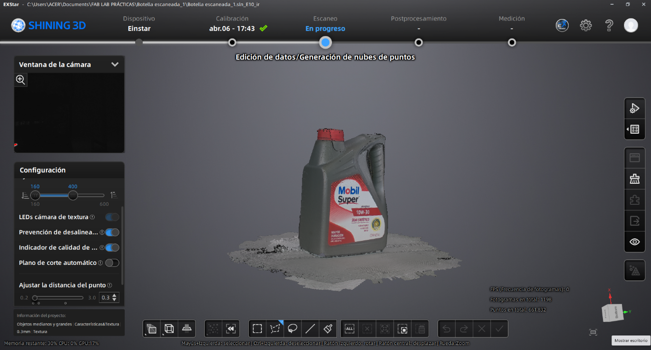
Step 12 ·
Next, we select the option to generate the Point Cloud in the side menu and wait for the system to process the information.
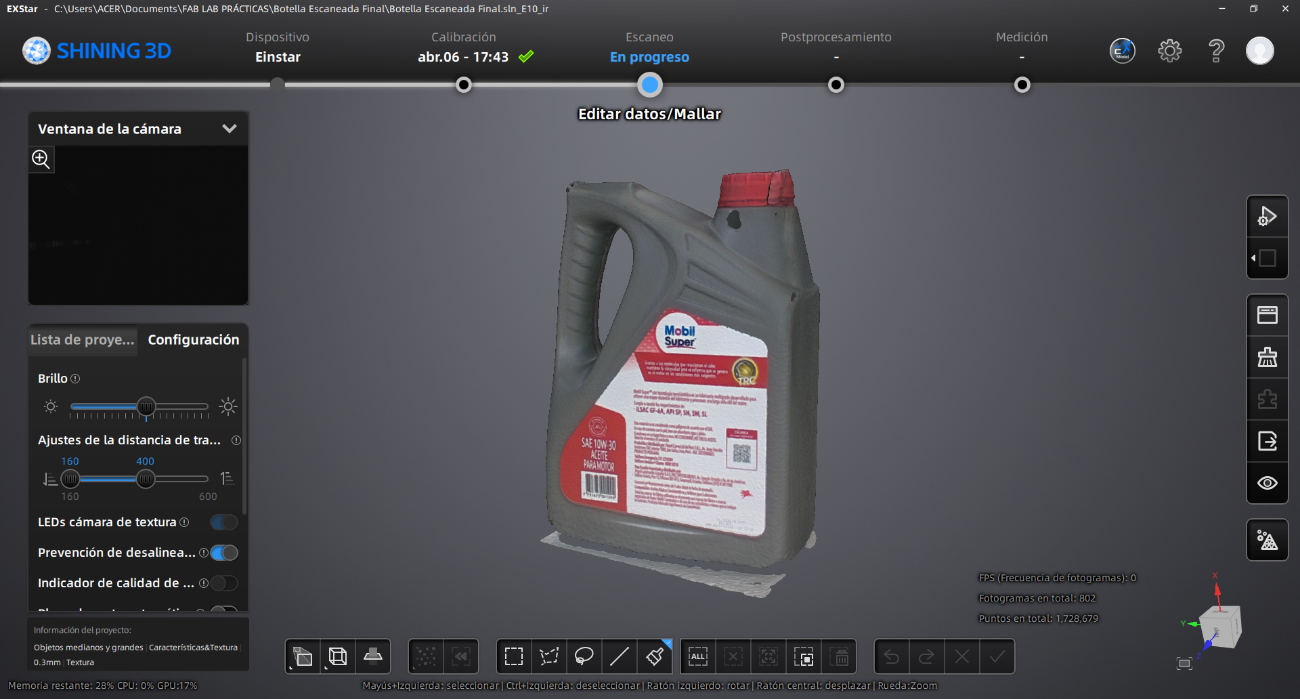
Step 13 ·
Once the point cloud is obtained, we use the side tool to transform the data into a polygonal mesh./p>
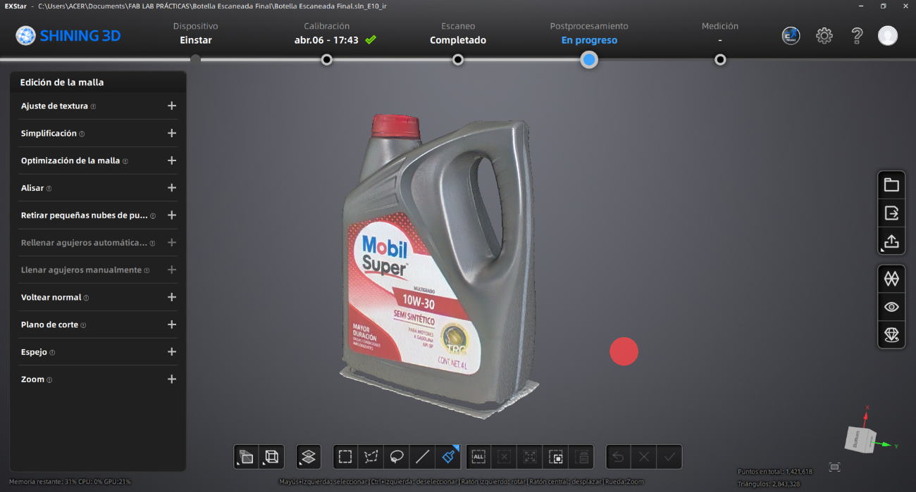
Step 14 ·
In this stage we edit the digital model to remove the scanned base and refine the contours of the piece using the functions in the bottom bar.
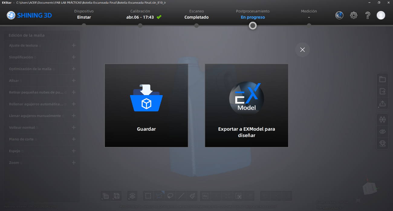
Step 15 ·
Once the editing is complete, we store the file in formats compatible with 3D manufacturing systems, such as STL or OBJ.
Step 16 ·
Finally, we execute the print command and, upon completion of the physical process, we remove the support structures from the part.
Conclusions
By designing, segmenting, printing, and scanning objects, you will learn how digital models are transformed into physical prototypes and how real-world objects are converted into editable 3D files. Most importantly, you will learn the relationship between printer settings and print quality. Parameters such as layer height, infill, supports, temperature, and print orientation directly influence the final result, dimensional accuracy, and structural stability of the printed parts. You will also learn that additive manufacturing allows you to create complex geometries and internal structures that would be very difficult or impossible to manufacture using subtractive methods. Furthermore, working with 3D scanning technologies allowed me to learn different methods for capturing real-world objects and converting them into digital meshes. During the scanning and post-processing stages, I improved my understanding of mesh cleaning, alignment, optimization, and export, while also recognizing the limitations and challenges of scan accuracy and capturing surface details.