Week 3 - Computer Controlled Cutting #
Hero shot: #

Group Assignment #
Link to this week’s group assignment
Laser Cutting #
Finding Kerf #
Kerf is one of the key parts into designing a construction kit with a good fit. Kerf is the amount of material taken away by the laser of the laser cutter (or could be the blade of a saw) when cutting a straight line. In other words, kerf is the thickness of the laser beam.
I’ve heard about Cuttle.xyz and wanted to give it a go. However, I found it hard to adjust. Being used to it, I kept searching for the kind of constraints the Fusion allows one to do. So I gave up Cuttle for this week. I might try it again later on.

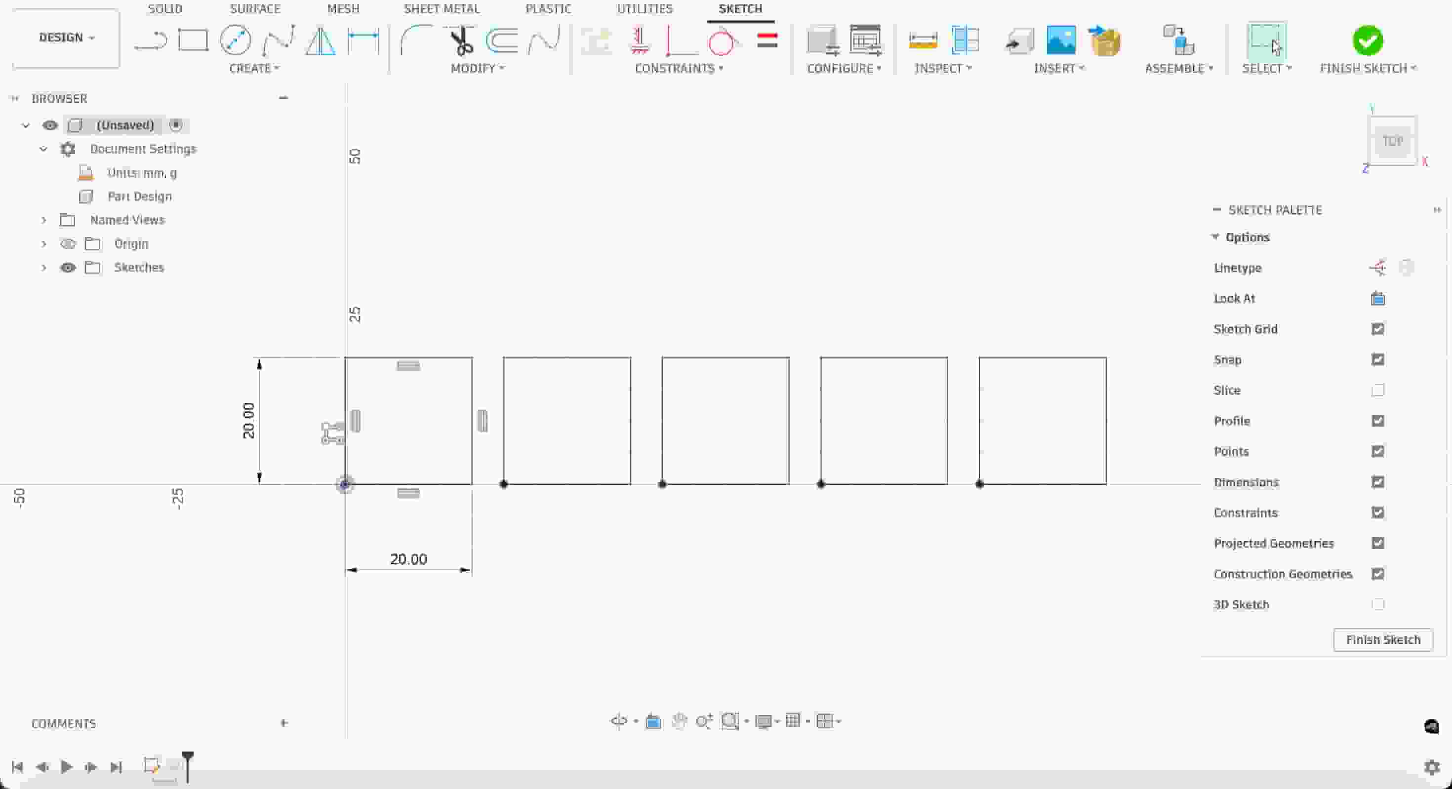
I returned to my one true friend, Fusion 360. I first wanted to figure out the kerf of the laser cutter we have in the lab. I created a simple document with 5 squares with sides of 20mm long and 5 mm in between.
I exported my design for kerf test as DXF and imported on xTool Studio connected to the xTool P3 Laser Cutter. As material I decided to use basswood plywood off thickness 3mm.

Then, I chose the appropriate material with the correct thickness.
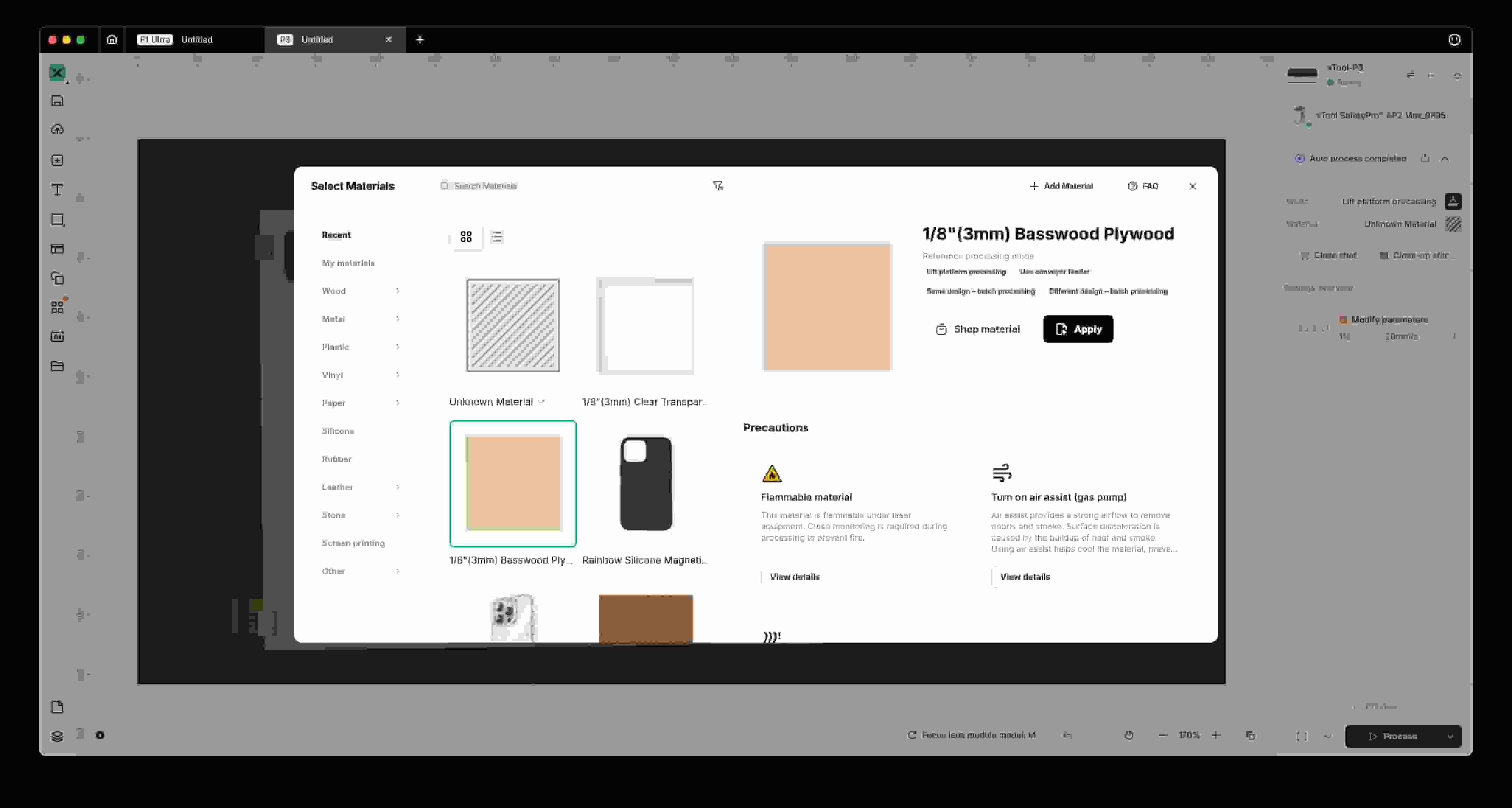
Upon choosing a material, we can use the “One-click set” option on the application. This is an option that helps you choose the right power and speed parameters for the given material. The settings are often accurate for the mentioned material, so this tool is pretty convenient. It also marks the suggested parameters with a dashed border. Using this tool, I set the power to 90% and the speed to 40mm/s.

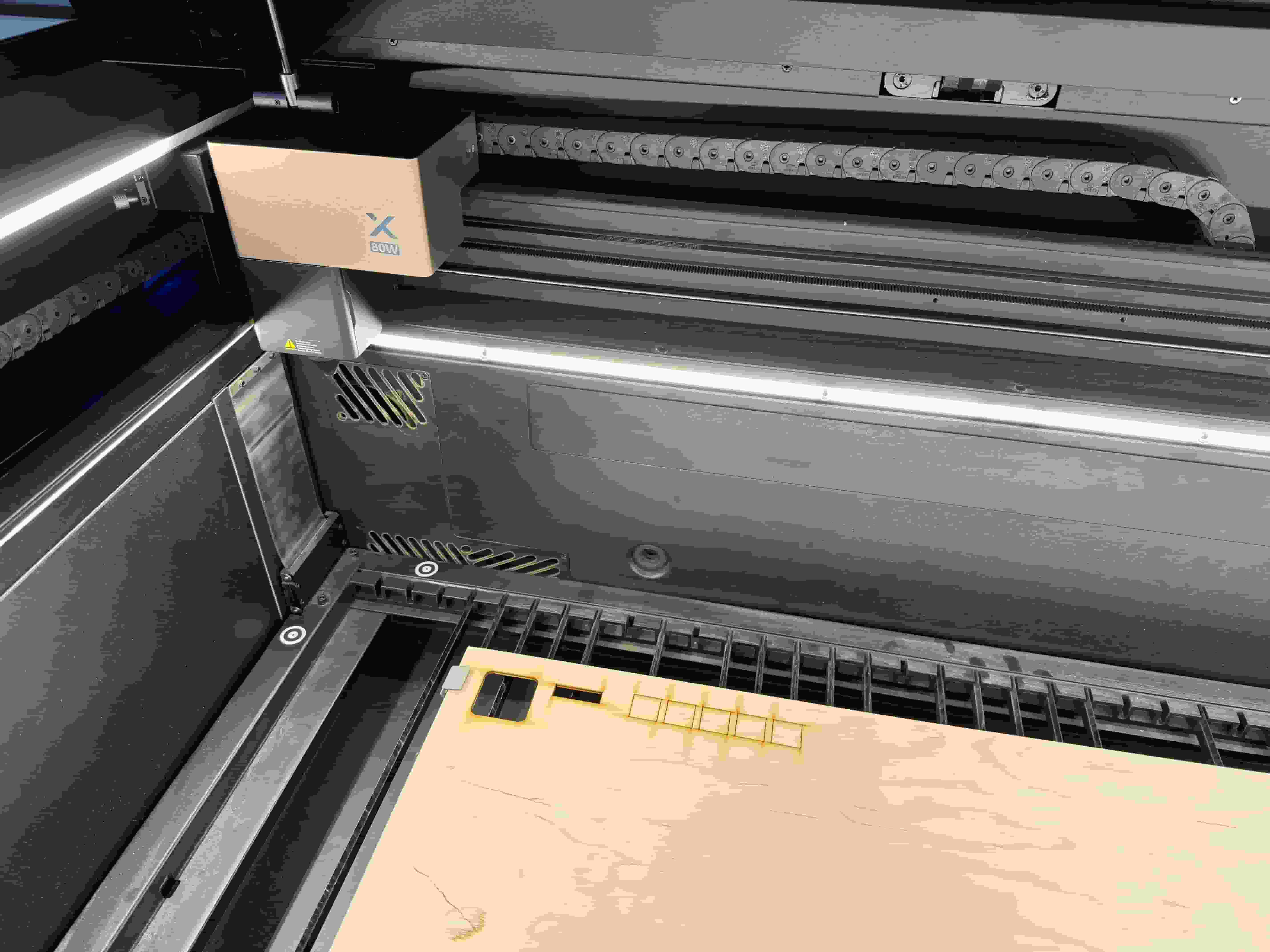
I headed over to P3 and pressed the button to start the process.
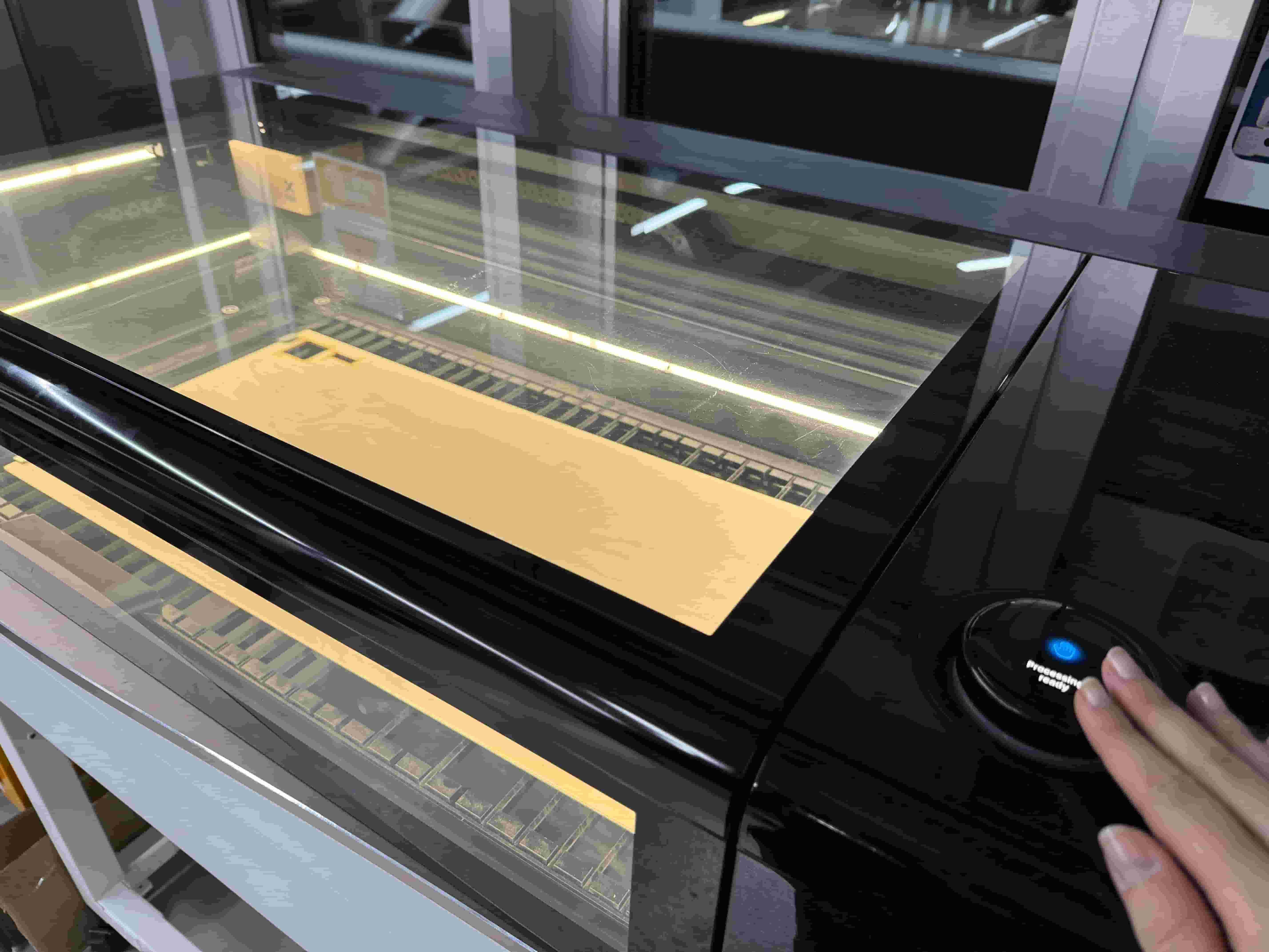
After a few seconds, the cutting process was finished.
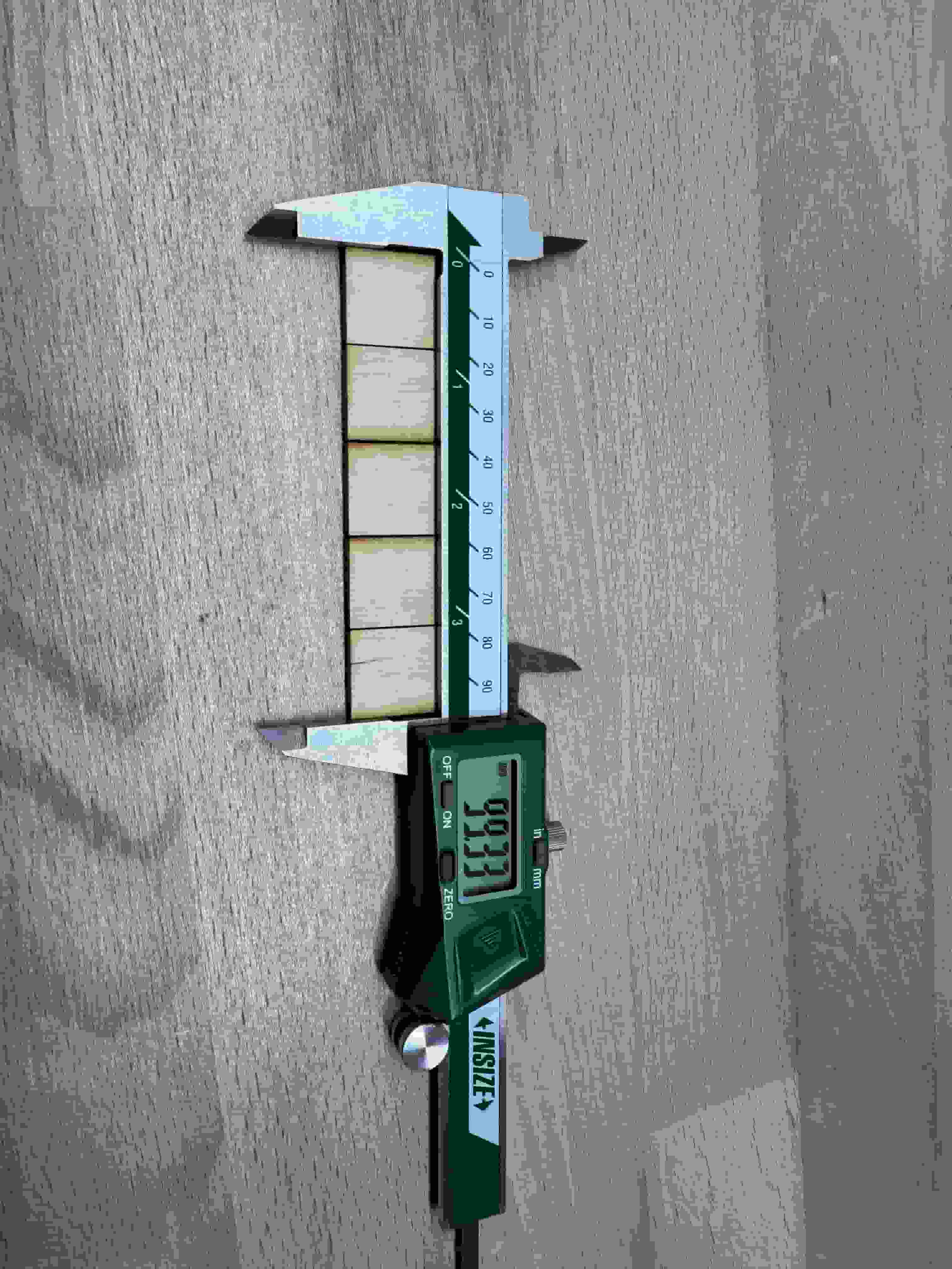
I used a digital caliper to calculated how much material I have left. In an ideal case with 0 kerf, every square piece would be 20mm long and, thus, the total measurement would be 100mm. However, the digital caliper read 99.33mm. So, the total material loss is 0.67mm for 5 pieces of square. This means the kerf is 0.67/5=0.134mm.
Below are my specifications for the kerf test:
Laser Cutter: xTool P3
Material Type: Basswood Plywood
Material Thickness: 3mm
Kerf: 0.134mm
Power: 90%
Speed: 40mm/s
Construction Kit #
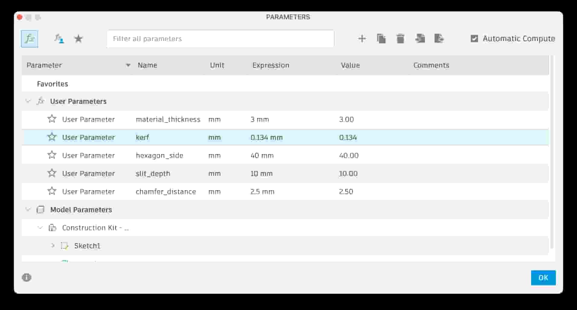
To keep things simple, I decided to use a hexagon. I thought about the possible parameters I shall need for this construction kit: hexagon side length, slit depth, material thickness, kerf,… Below are my final parameters.
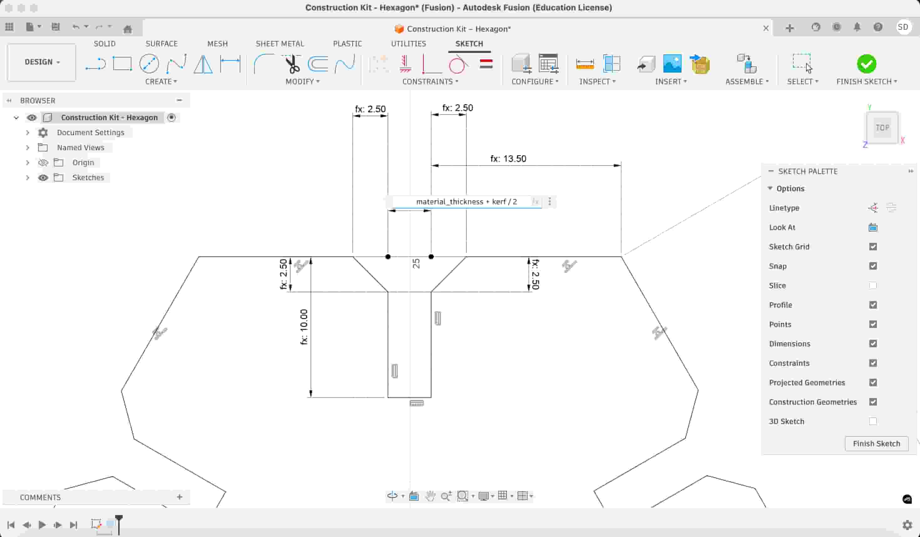
I created a hexagon sketch including a slit with a width of material_thickness+kerf/2 and depth slit_depth. Also added some chamfers for ease of alignment.
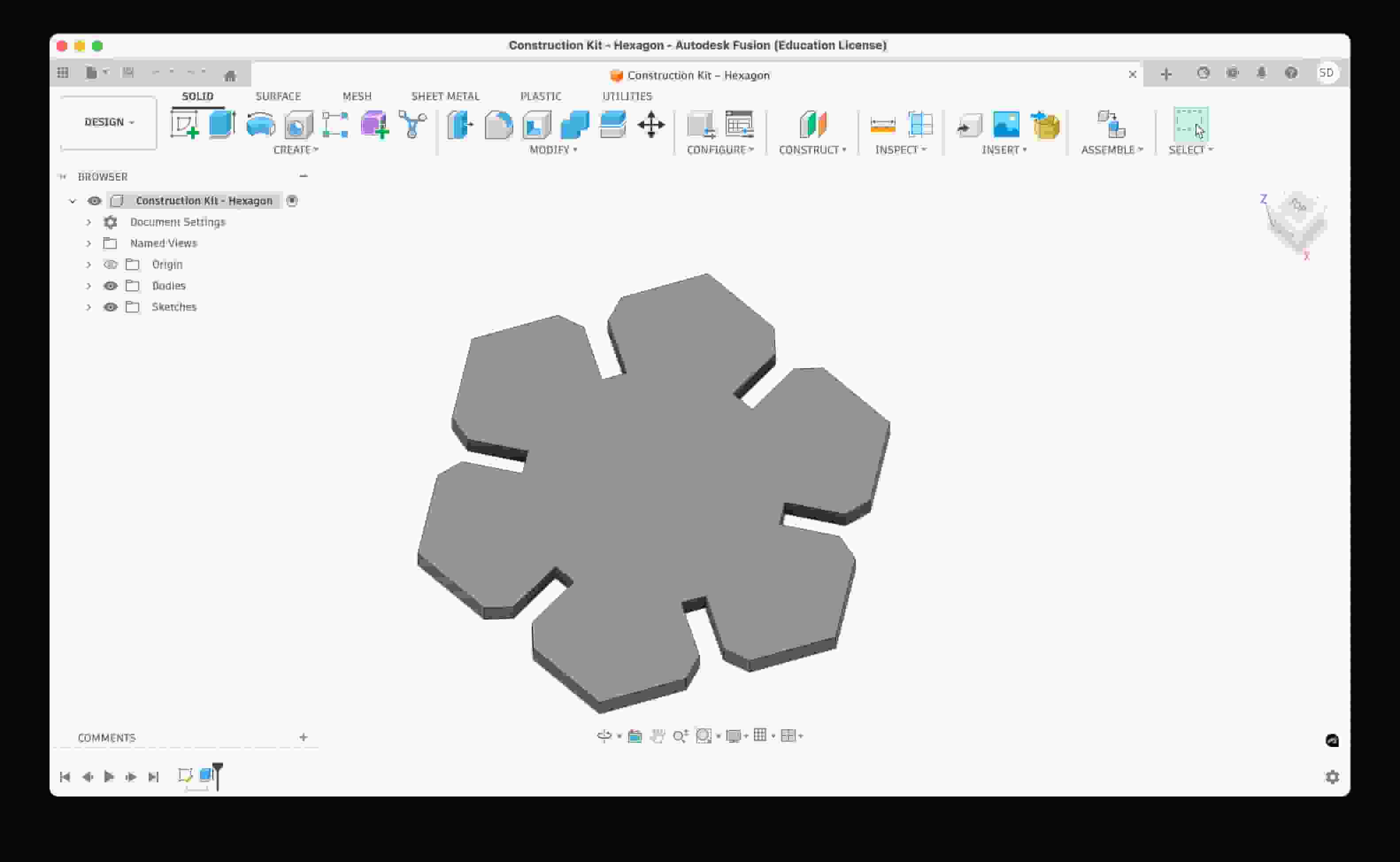
After that, I used ‘Circular Pattern’ to repeat the slit on all of the sides. Then, I extruded my sketch.
I wanted to make another piece. I decided it would be a triangle with size smaller than the other design. I started with creating my sketch. Similar to the hexagon piece, I set up my parameters and created slits using chamfers and a circular pattern.
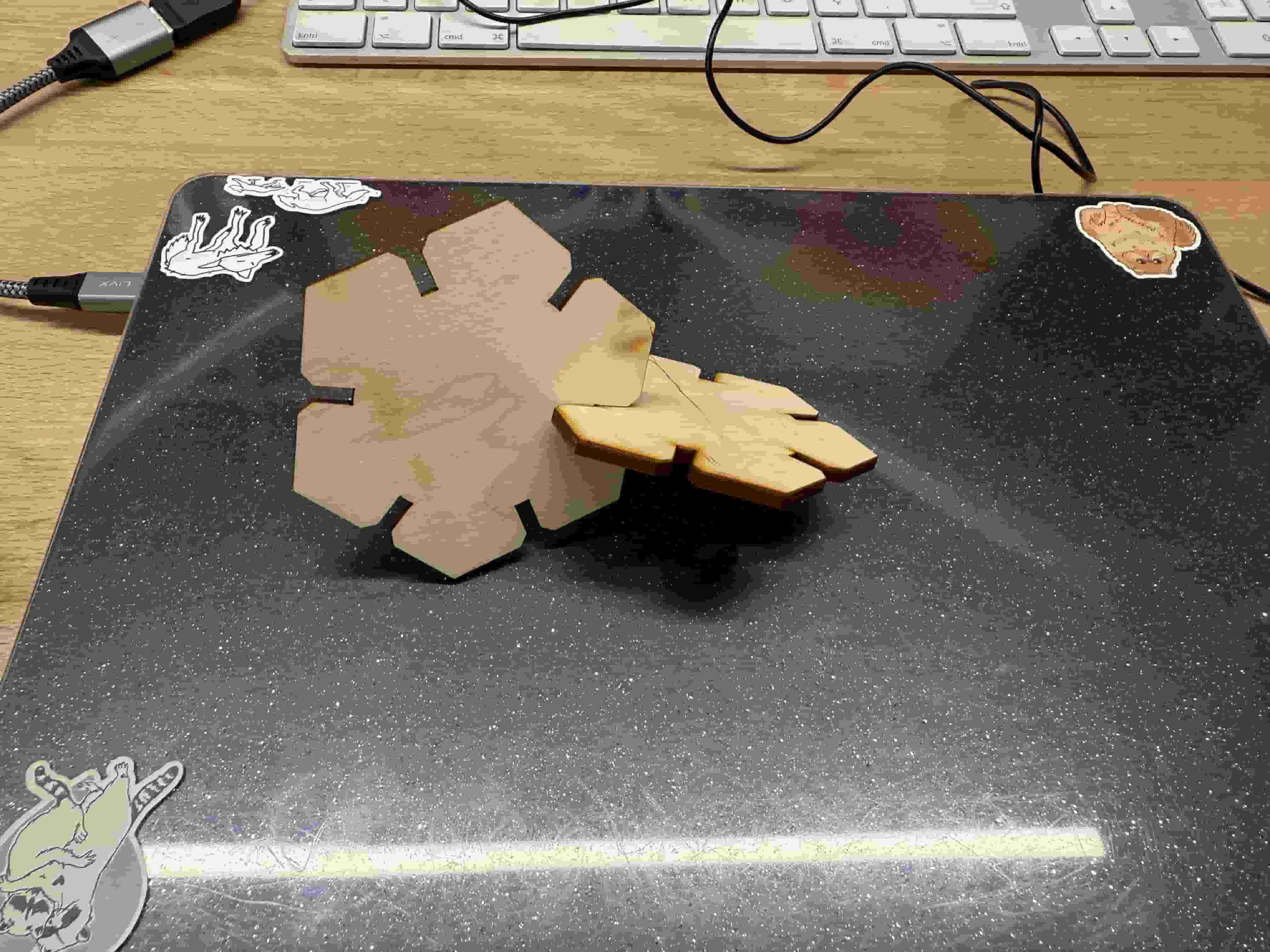
I first wanted to try if my construction kit was gonna work. With hexagon_side being 50mm. I followed the same steps to cut with xTool P3 using the same settings.
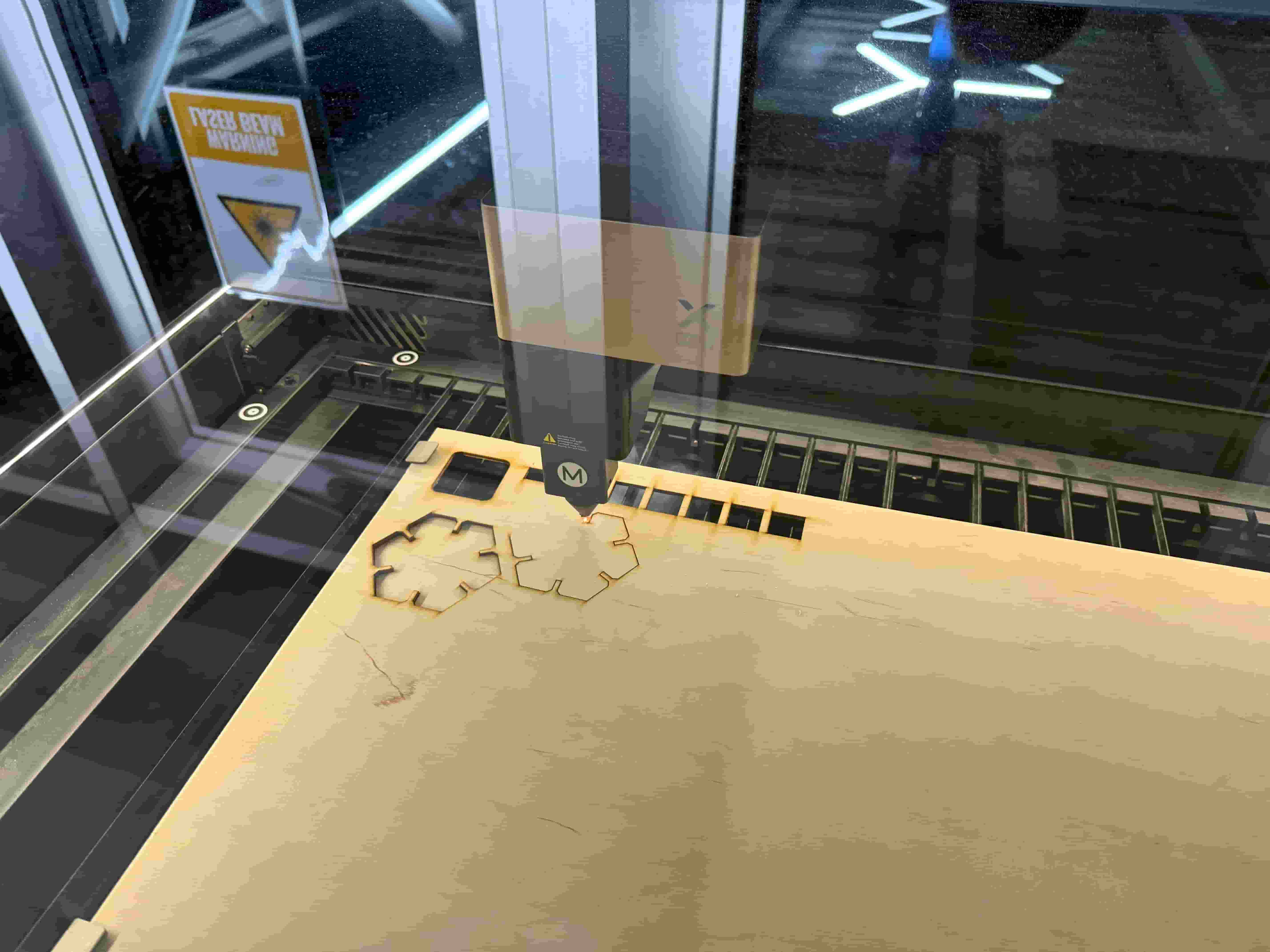
I tried the test cut and it seemed to work quite well! Test successful! However, the design was quite big so I decided to set the hexagon_side to 40mm.
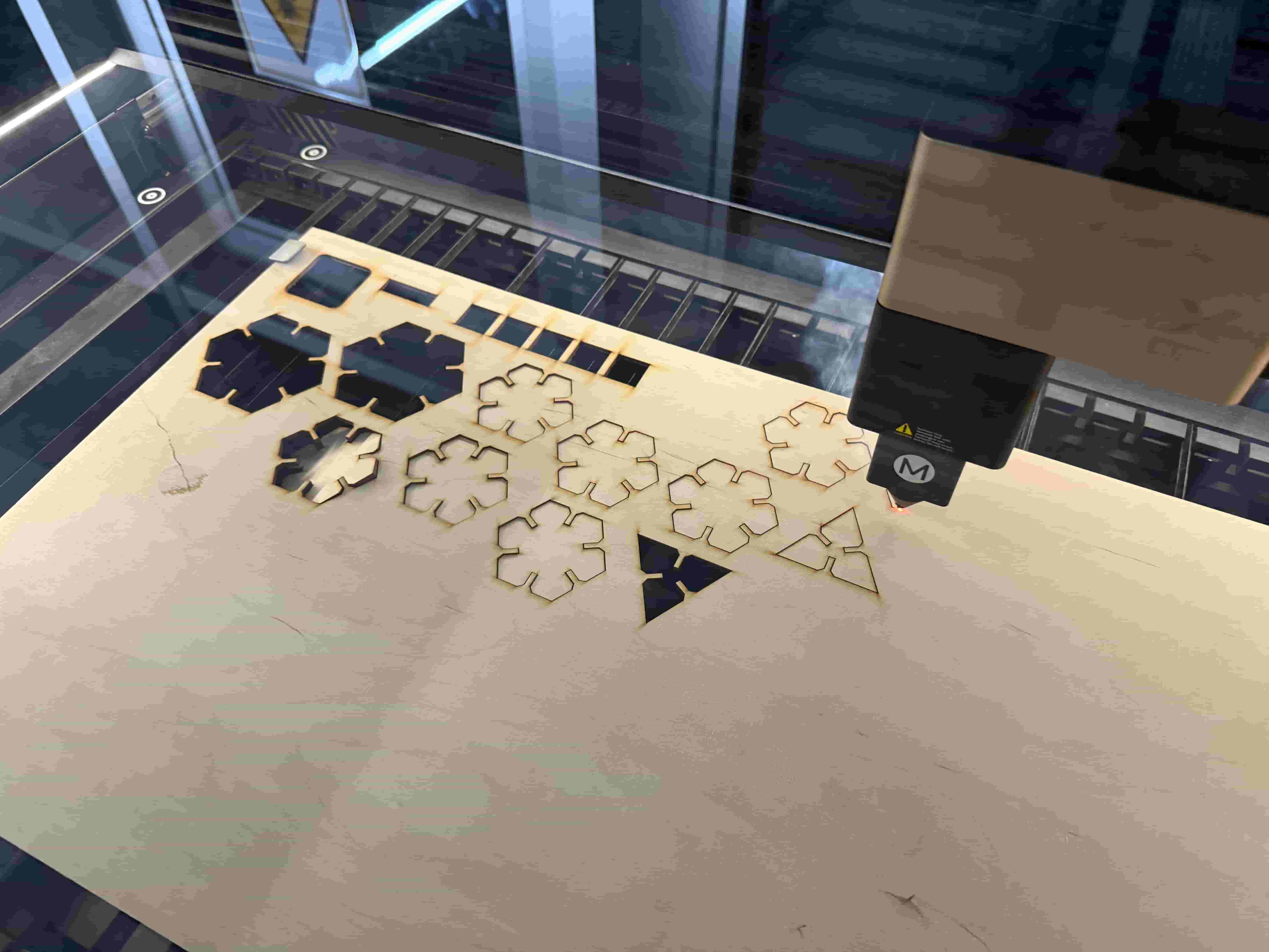
Then I cut some of my pieces, both hexagons and triangles.
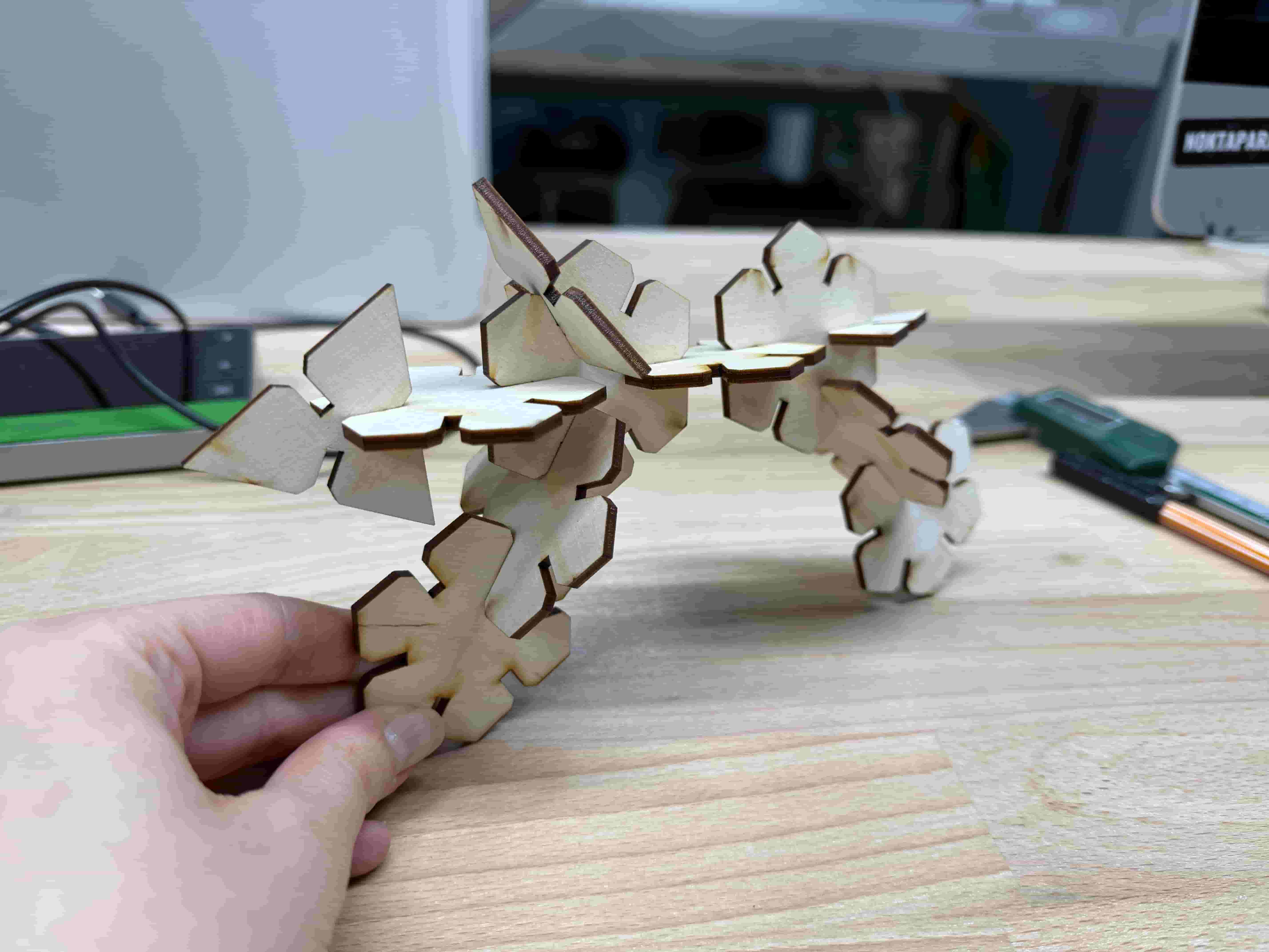
Model Constructions #
I tried using the pieces to construct some different things. The first things I made were a snake and a crab .)
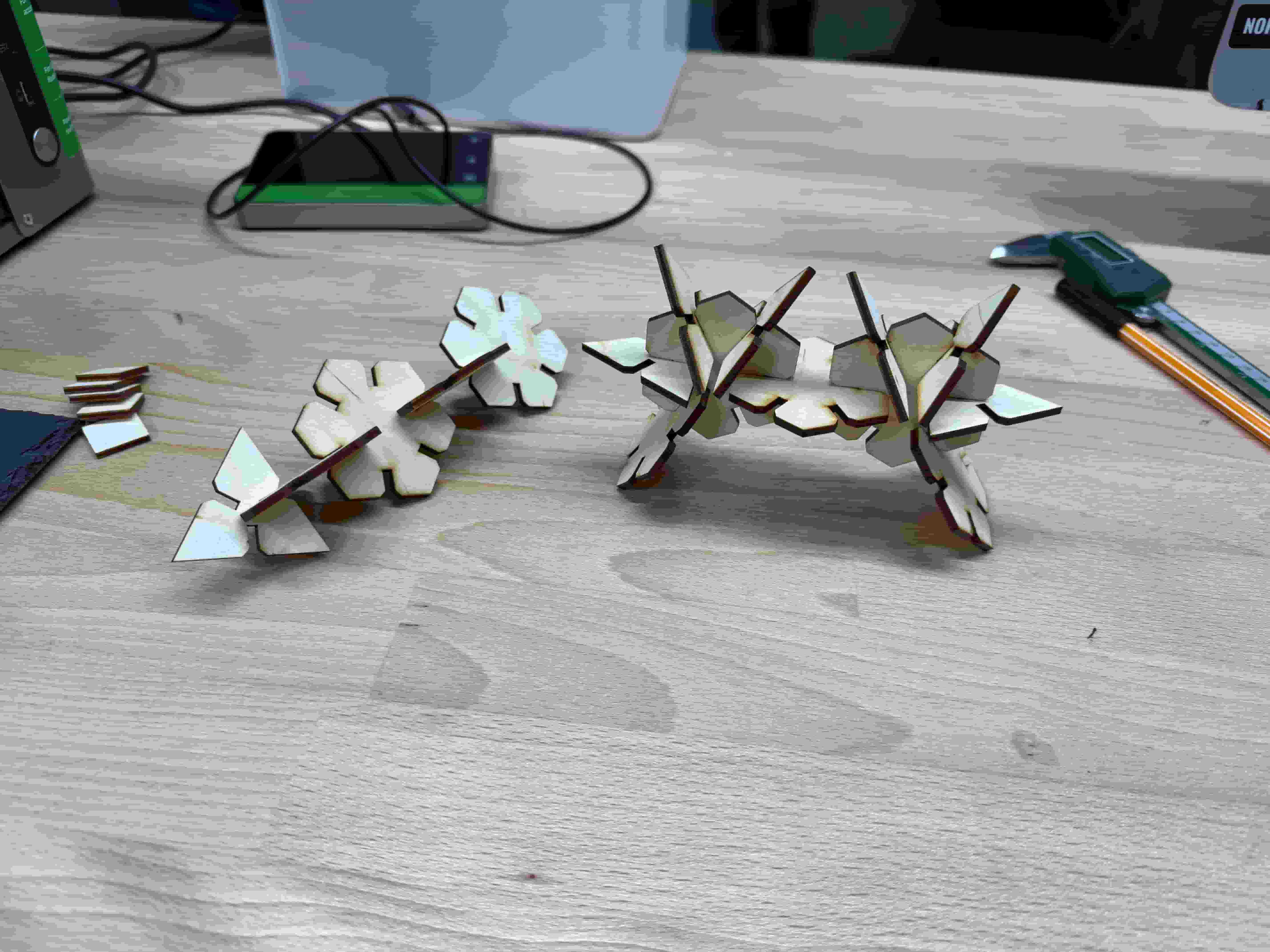
I also managed to make a motorcycle.
Vinyl Cutting #
Cricut Maker 4 #
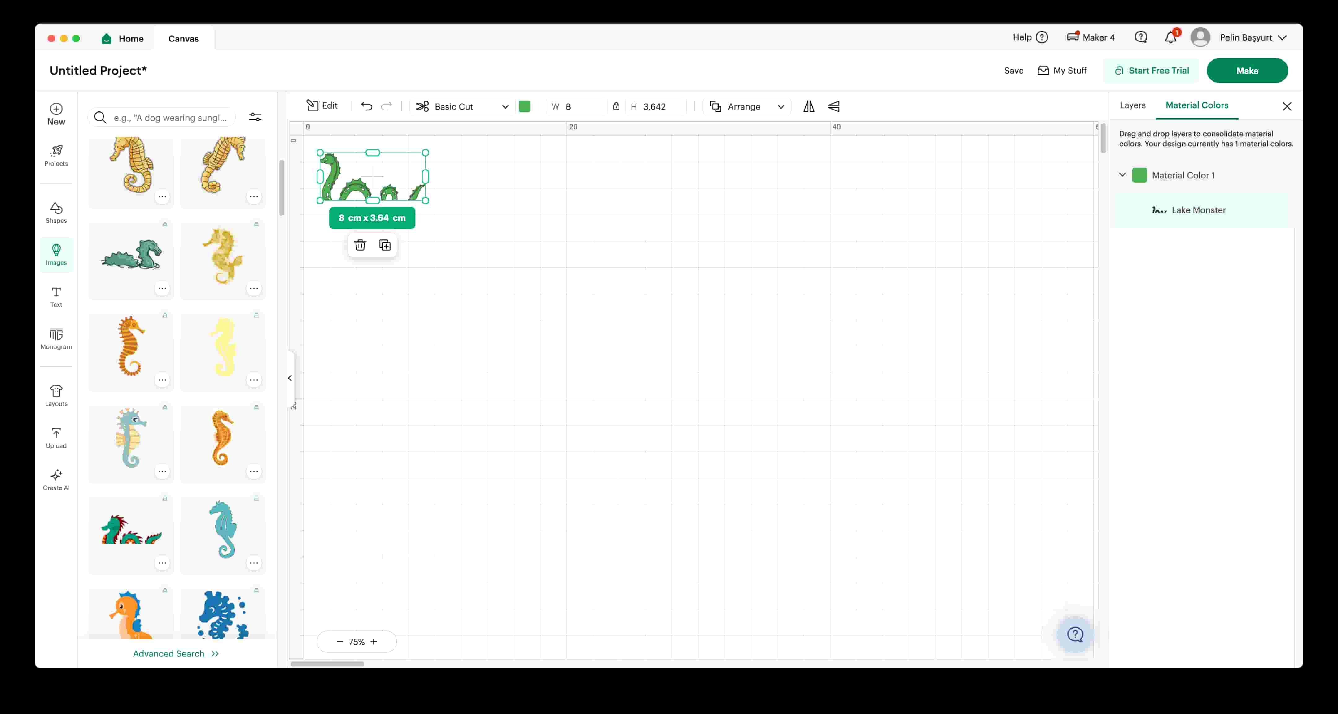
I liked the pre-designed sea dragon drawing and decided that I wanted it as a sticker :3. I adjusted the size of it on Cricut Design Studio. and clicked on “Make” when ready.
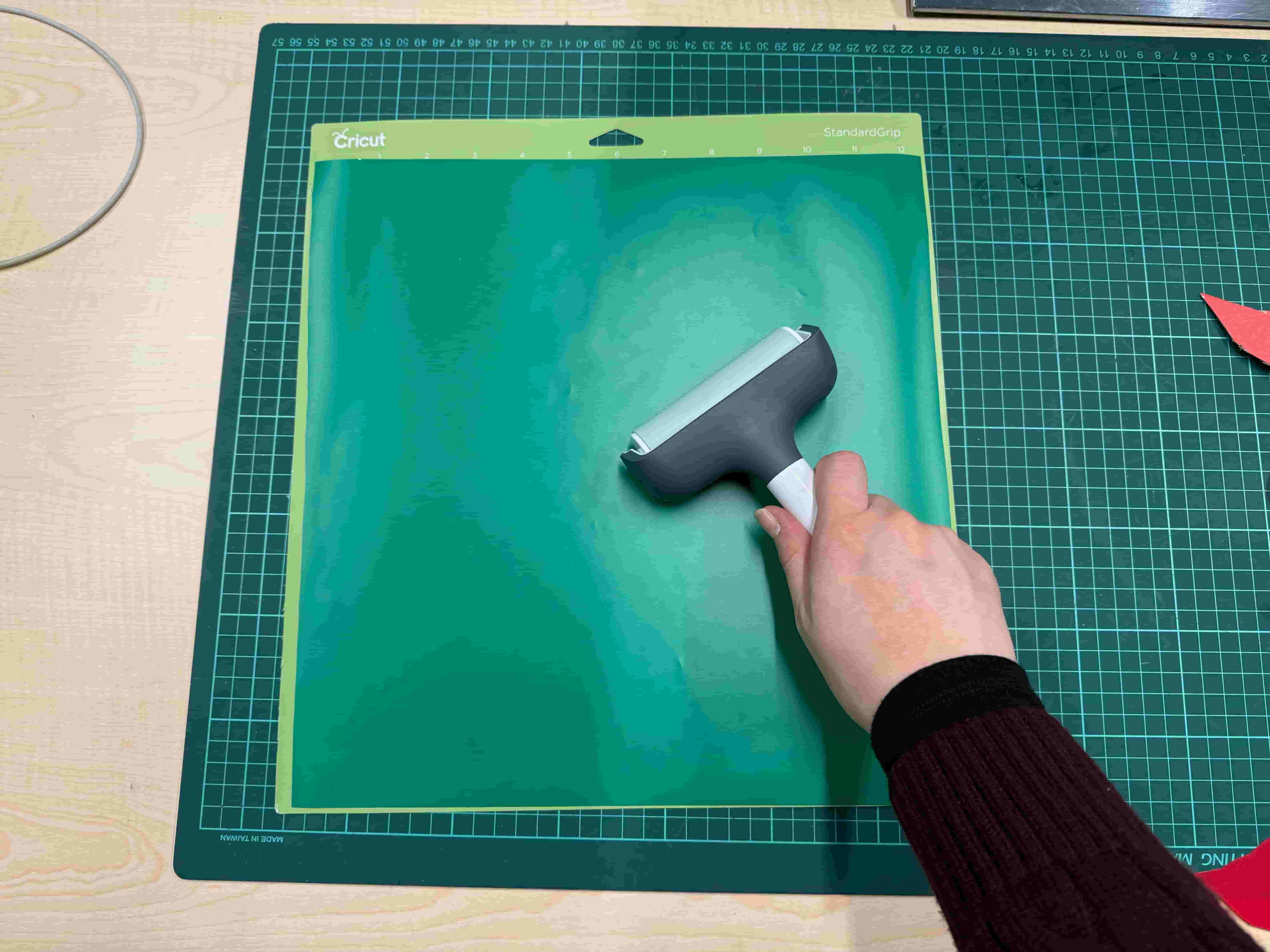
I took the Cricut cutting mat of size 30.5cm x 30.5cm. I chose the green Permanent Smart Vinyl and cut a piece of it. I used a roller to stick it completely without air bubbles onto the mat completely.
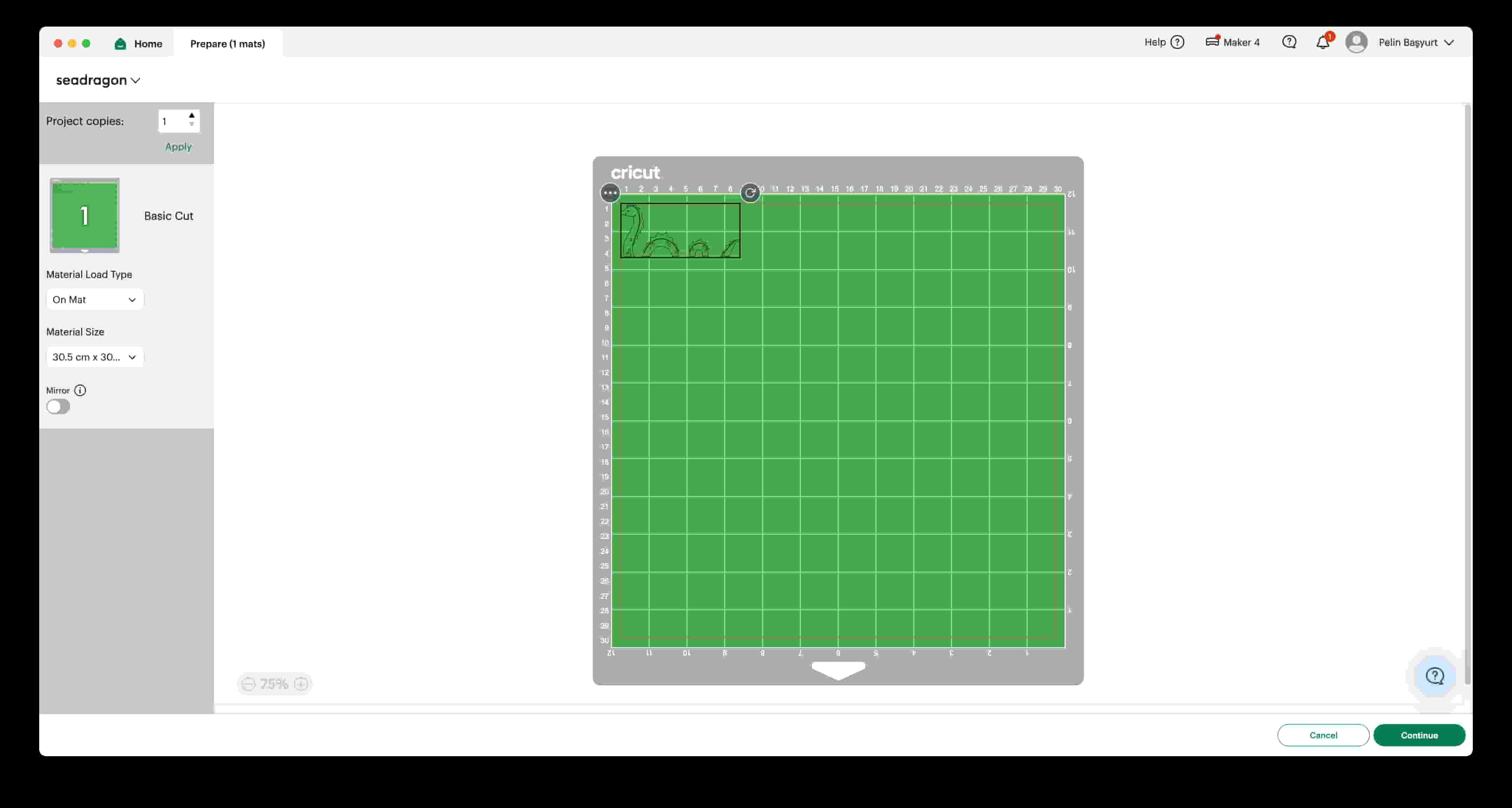
I opened the Cricut Maker 4. Then I went over the the computer and chose the “On Mat” option since I am using a mat.
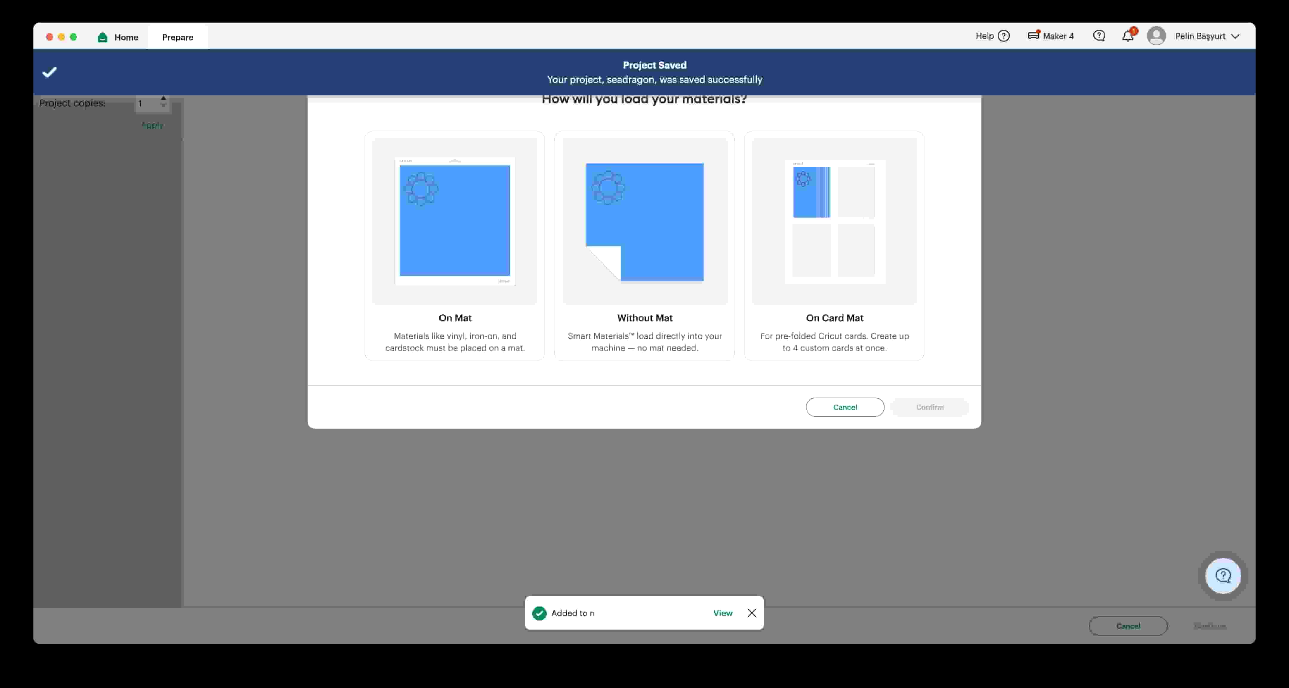
After choosing the correct mat size on the left, I adjusted the design on the mat and clicked on “Continue”.
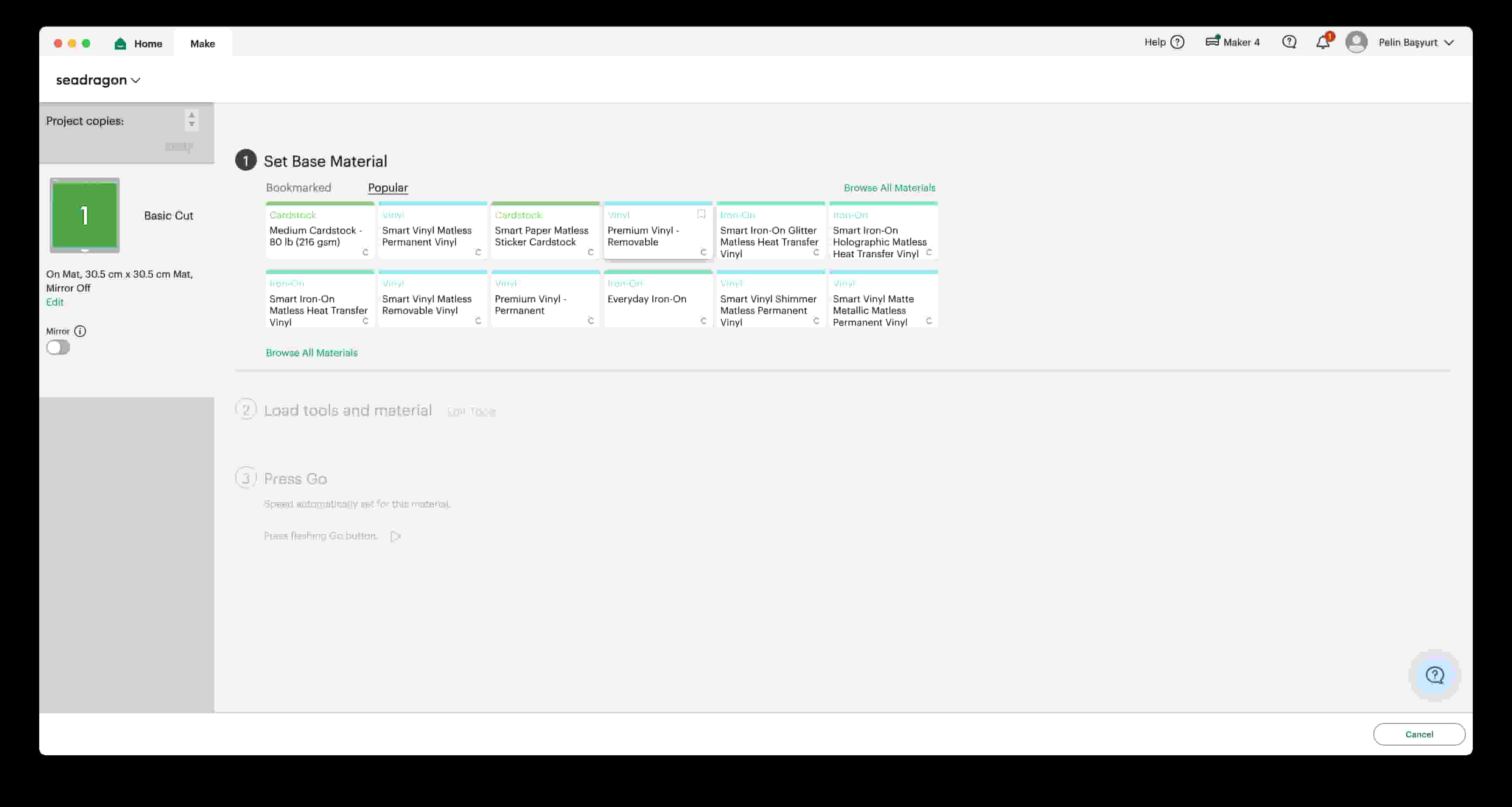
I select the material as Smart Vinyl Matless Permanent Vinyl. Since I chose the “On Mat” option, the material being matless vinyl is not a problem.
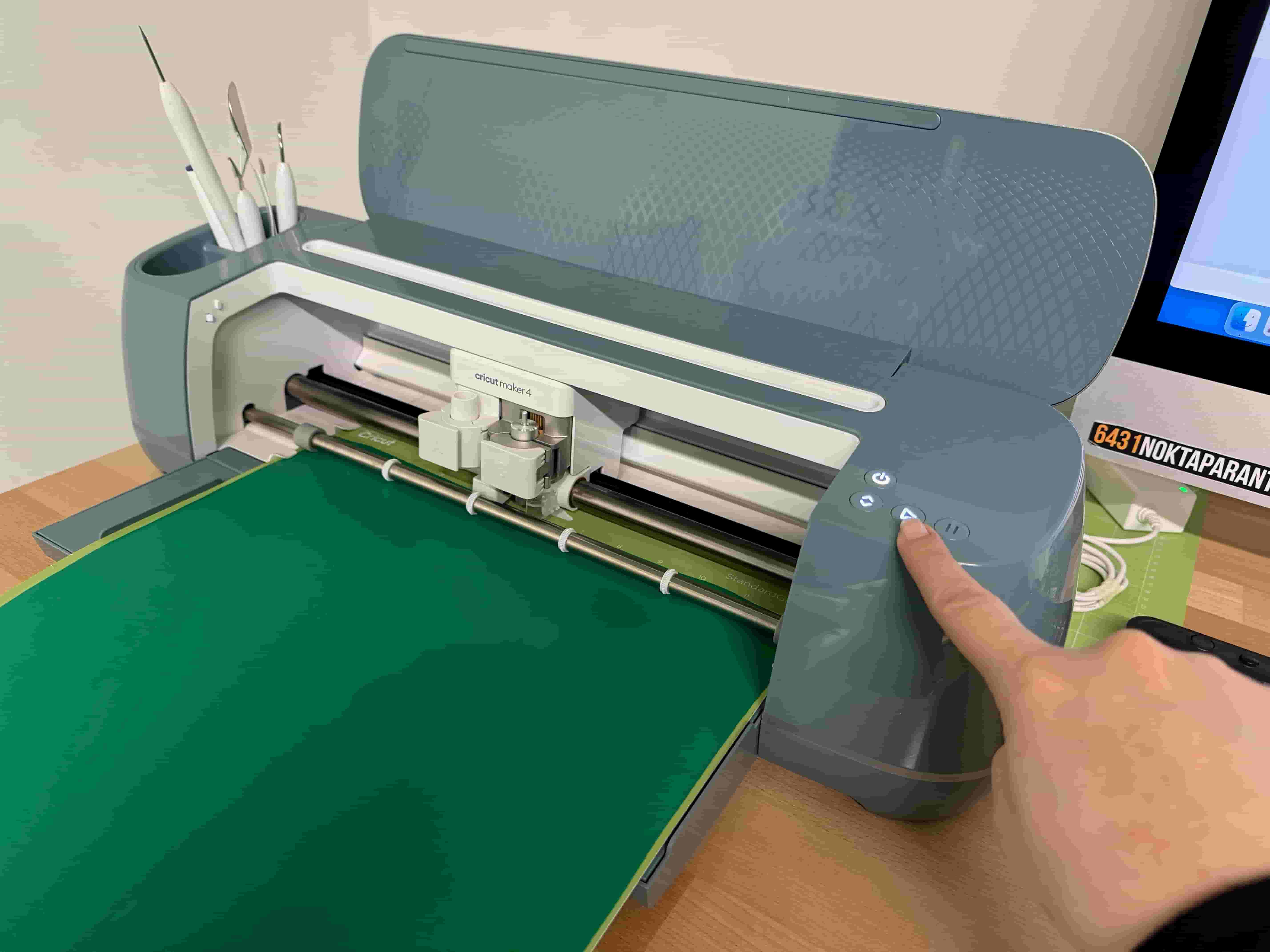
I loaded the material and started the vinyl cutting.
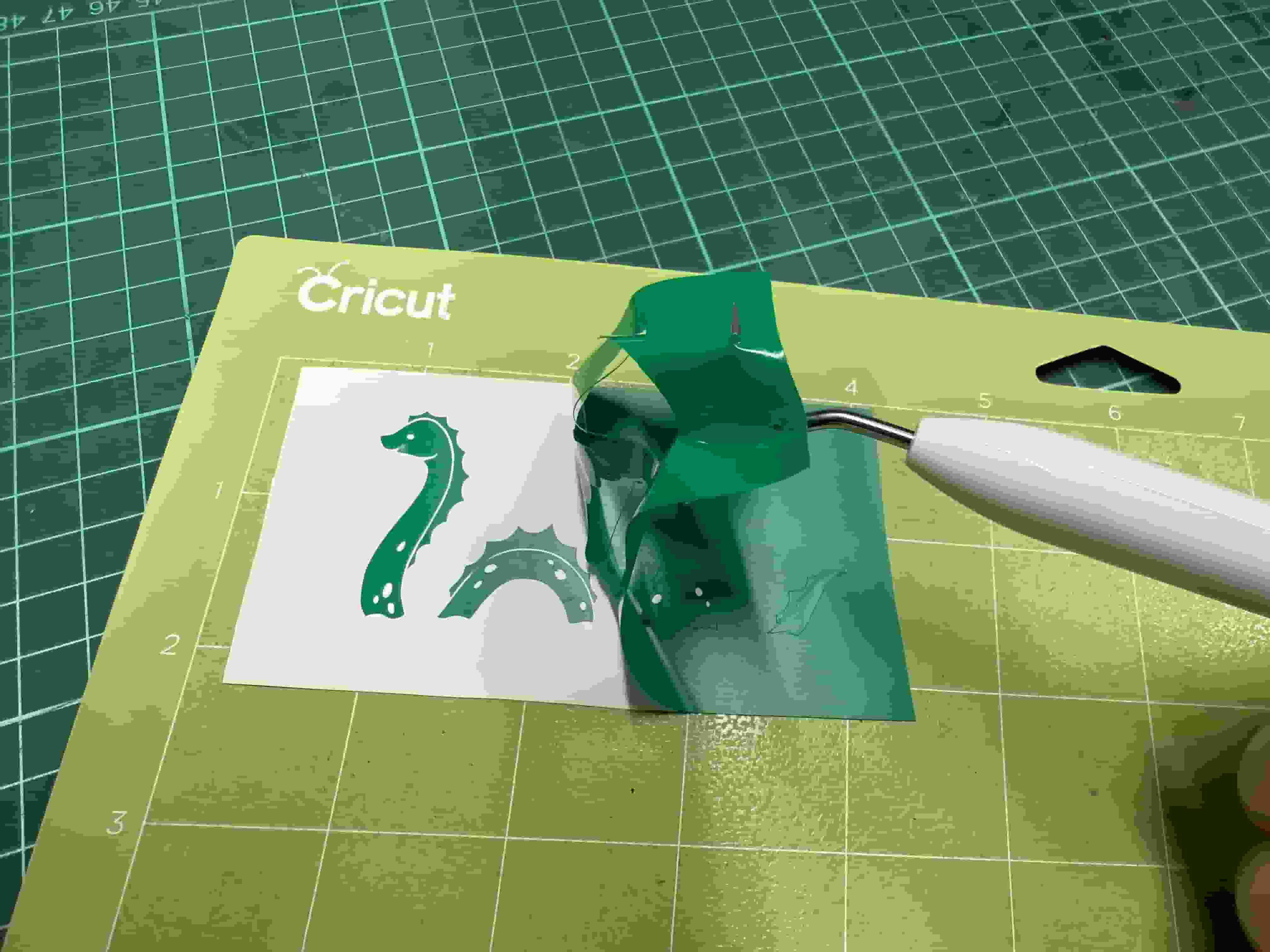
When the operation is done. I used a weeder to weed the remaining vinyl around the sticker.
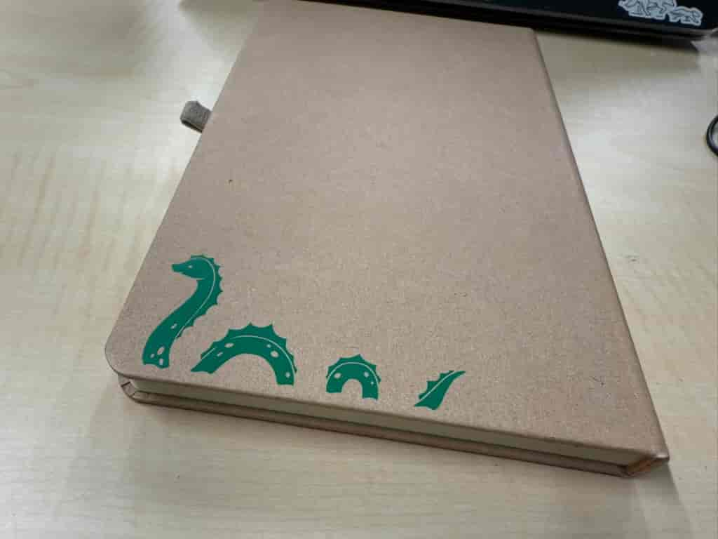
I used transfer tape to take out the whole sticker as is and placed it onto my notebook.
![]()
I took off the transfer tape and admired the design!
Roland BN-20A Printer and Cutter #
The Roland BN-20A is the perfect machine to print and cut any design onto a vinyl. It is exceptionally useful for making your custom stickers and producing them in bulk. The ability to print and also cut more quickly are the main differences from the Cricut Maker 4.
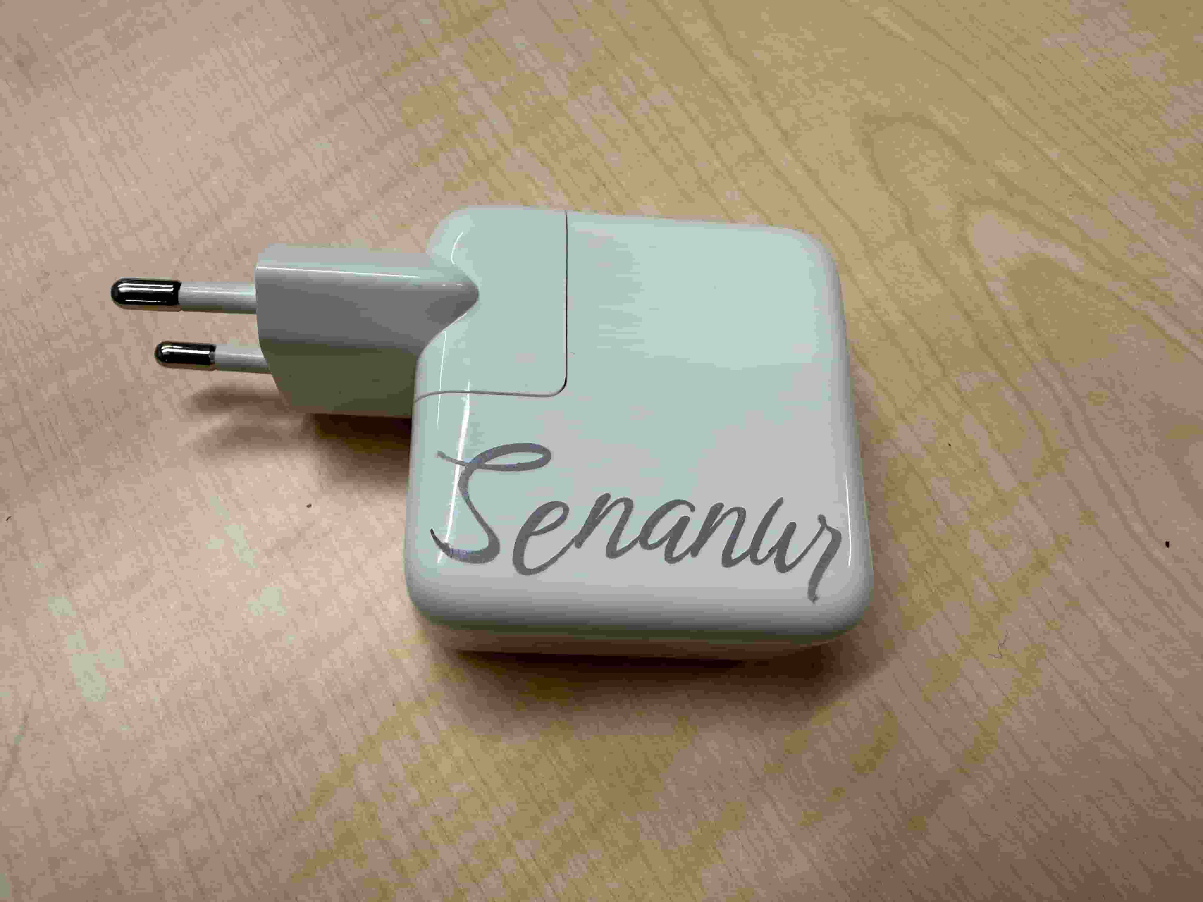
I spend all day at the lab and sometimes students borrow my charger. I decided to put my name on it so that I can find it if lost. So, I made a design with my name on it. I chose a font, then used the CutContour color as stroke color to designate the cutting routes. This is the color designated by Roland VersaWorks for cutting lines.
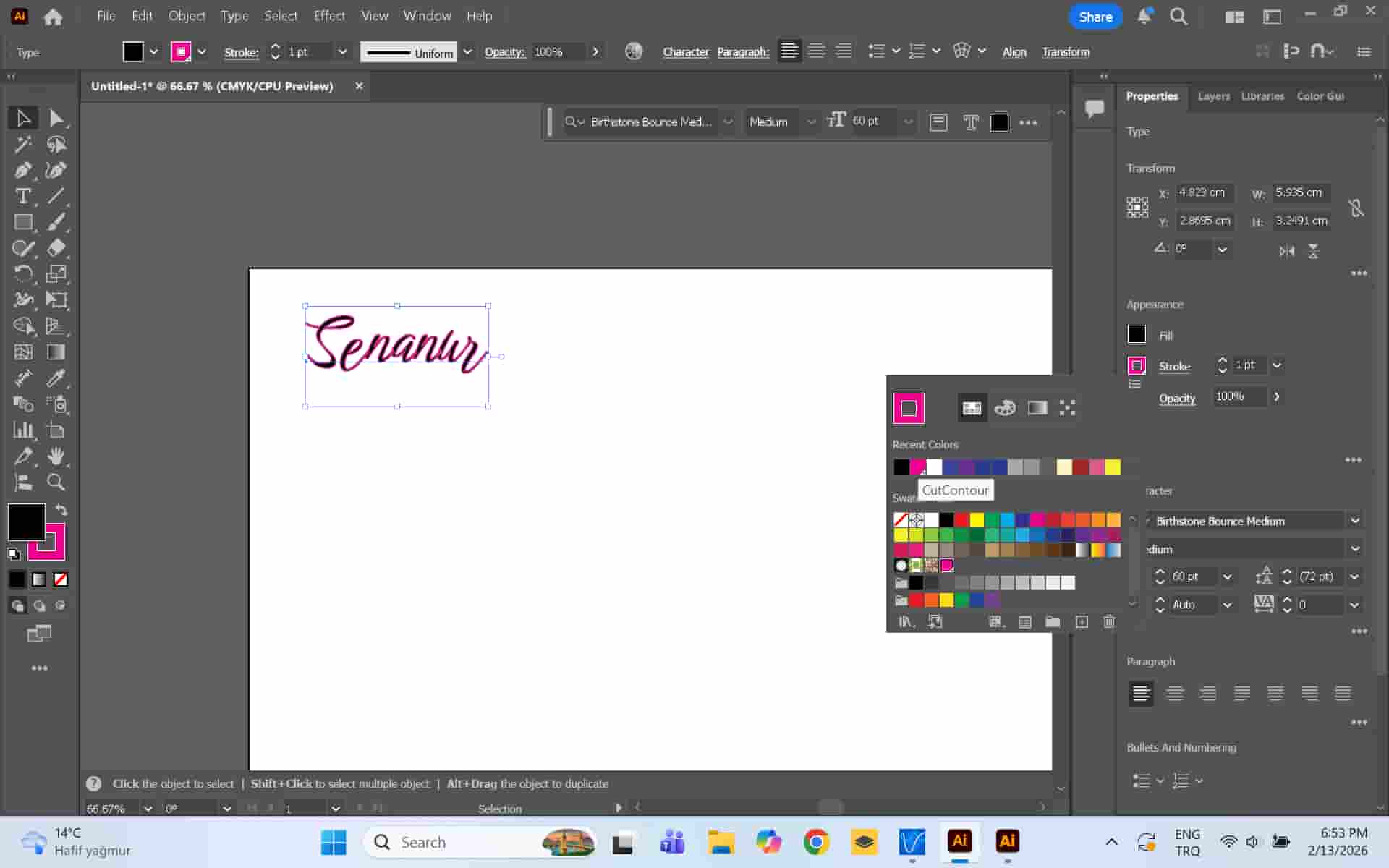
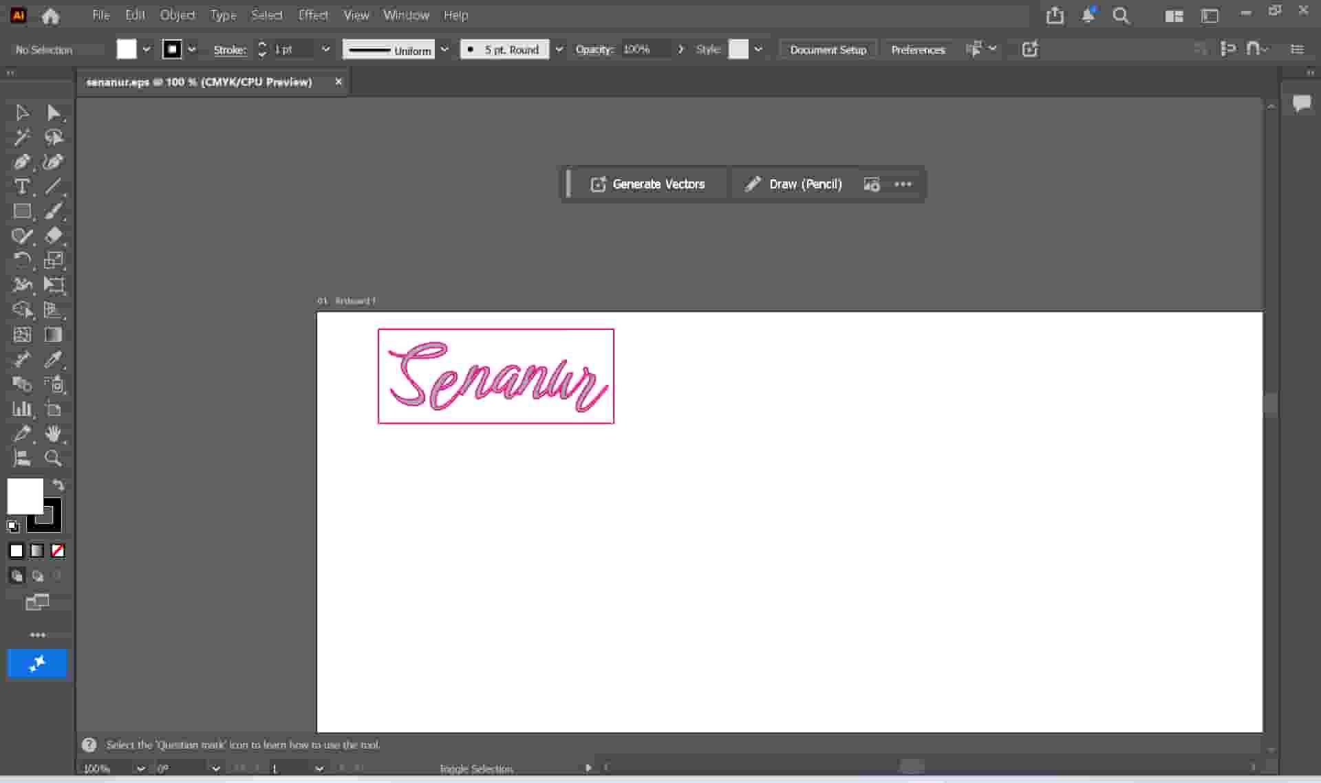
I also added a rectangle around it to help me use the transfer tape easily. I saved the design in EPS format. This is what the VersaWorks application uses.
I dragged the file onto VersaWorks. After doing the necessary adjustments like size and placement, I started the print.
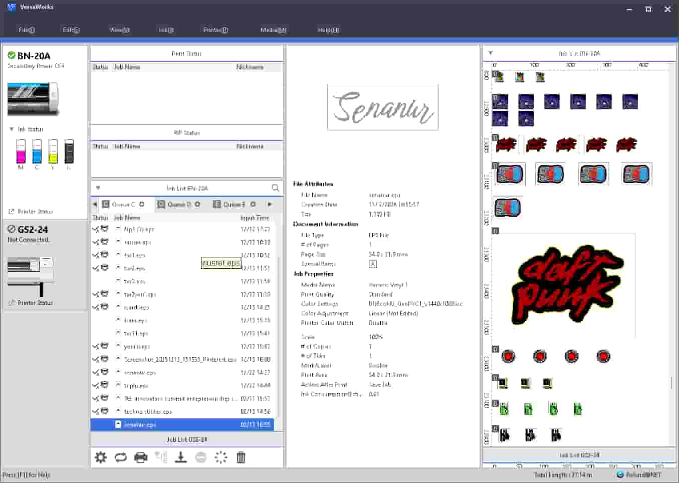
After the operation was done, I could see my sticker was printed and cut just as I wanted.
![[bn20a-print.jpg]]
Files:
- Construction Kit: Hexagon and Triangle Parts (DXF)