04 Embedded programming
Reflection
This week was quite challenging, as I didn't have enough experience to dive into embedded programming on my own. Starting from scratch felt overwhelming, but I was lucky to find helpful tutorials that guided me through the basics.
AI tools like Deepseek became an invaluable learning companion,like having a patient teacher available 24/7, never judging even the silly questions. Continued discuss with AI can avoid the hallucination result. And I can run the program to double check if it is right.
Annotated each line really helps me a lot. It allowed me to break down and understand each detail, commands, functions, and algorithms. I know this is just the beginning, and there's still a long way to go.
Schedule
| Time | Wed | Thu | Fri | Sat | Sun | Mon | Tue |
|---|---|---|---|---|---|---|---|
| 08:00-10:00 | |||||||
| 10:00-12:00 | Browse through the data sheet | Qpad -Tetris | |||||
| 12:00-14:00 | |||||||
| 14:00-17:00 | Follow tutorial | Qpad -Tetris | Document | ||||
| 17:00-22:00 | LED screen test | ||||||
| 22:00-00:00 | Neil's class | ||||||
| 00:00-01:00 | class |
Group Assignment
- [ ] Demonstrate and compare the toolchains and development workflows for available embedded architectures.
Datasheet ESP32, RP2040, ATmega328
Seeed Xiao RP2040 uses the RP2040 chip. DFRduino UNO R3 is an ATmega328P-based development board. For group work I will mainly compare these two boards and chips.
| Feature | RP2040 | ATmega328 | ESP32 |
|---|---|---|---|
| Dev Board | Seeed Xiao | Dfrobot UNO | Seeed Xiao |
| Wireless Connectivity | none | none | Wi-Fi,Bluetooth |
| SRAM | 264 KB | 2 KB | 520 KB |
| CPU | 32-bit ARM Cortex-M0+ | 8-bit AVR | 32-bit Xtensa LX6 |
| Cores | Dual-core | Single-core | Dual-core (or single-core variant) |
| Clock Speed | Up to 133 MHz | Up to 20 MHz | Up to 240 MHz |
| Flash Memory | 2 MB (external) | 32 KB (internal) | 4 MB (typical) |
| Digital I/O Pins | 11 | 14 | 11 |
| Logic Level | 3.3V | 5V | 3.3V |
| Board Dimensions (LxWxH) | 20 x 17.5 x 3.5 mm | 75 x 54 x 15 mm | 21 x 17.8 x 5 mm |
| Peripherals | RP2040 | ATmega328 | ESP32 |
|---|---|---|---|
| UART | 2 | 1 (USART0) | 3 |
| I2C (TWI) | 2 | 1 (TWI) | 2 |
| SPI | 2 | 1 | 4 (SPI0, SPI1, SPI2, SPI3) |
| PWM | 16 channels | 6 channels | LEDC (16 channels) + MCPWM modules |
| ADC | 4 channels, 12-bit | 6 channels, 10-bit | Up to 18 channels, 12-bit (known non-linearities) |
| Timers | 2x PLLs, watchdog | 3x timers (Timer0, Timer1, Timer2) | 2x timer groups (TIMG0, TIMG1) + FRC timer |
| Special/Unique Peripherals | 8x PIO state machines (Programmable I/O) - USB 1.1 controller - QSPI controller for external flash | -1 KB EEPROM - Analog comparator - External interrupts - Brown-out detection | -Wi-Fi + Bluetooth - Ultra-Low-Power (ULP) co-processor - Touch sensors - Hall sensor - Cryptographic acceleration (AES, SHA, RSA) - Ethernet MAC - CAN (TWAI) controller - I2S audio interface - RMT (remote control) - Pulse counter (PCNT) |
UART: Universal Asynchronous Receiver/Transmitter A hardware module for serial communication between devices using two lines (TX, RX) without a shared clock.
- GPS modules (e.g., NEO-6M)
- Bluetooth modules (HC-05/HC-06)
- 4G/GSM modules (SIM800L)
- Serial displays
- Some LiDAR modules (e.g., RPLIDAR)
I2C(TWI): Inter-Integrated Circuit / Two-Wire Interface, A multi-master, multi-slave serial bus using two lines (SDA, SCL) to connect multiple devices, each with a unique address.
- Temperature/humidity sensors (DHT12, SHT30)
- Pressure sensors (BMP280)
- Accelerometer/gyroscope (MPU6050)
- OLED displays (0.96 inch)
- EEPROM chips (AT24Cxx series)
SPI: Serial Peripheral Interface, A high-speed, synchronous serial interface using four lines (MISO, MOSI, SCLK, CS) for full-duplex communication.
- SD card modules
- TFT color displays (e.g., ILI9341)
- SPI Flash chips (W25Qxx series)
- High-speed ADC modules
- RFID readers (RC522)
PWM:Pulse Width Modulation, A technique that simulates analog signals by rapidly switching a digital signal and varying the duty cycle (percentage of time the signal is high). Used for motor speed control, LED dimming, etc.
- LED strips/lighting
- DC motor drivers (e.g., L298N)
- Servo motors (e.g., SG90)
- Passive buzzers
- Heating pads / MOSFET control
ADC: Analog-to-Digital Converter A hardware module that converts continuous analog voltage into discrete digital values, allowing microcontrollers to process real-world analog signals.
- Soil moisture sensors
- Photoresistor (LDR) modules
- Potentiometers / game joysticks
- Hall effect current sensors
- Flame/smoke sensors (analog output)
- Microphone sound sensors
Timers: Timers / Counters, Hardware modules that count clock cycles or external events to generate precise delays, periodic interrupts, PWM signals, or measure pulse widths.
- Encoders for speed measurement
- Ultrasonic distance sensors (measuring echo pulse width)
- Frequency counters
- Periodic sensor data sampling
Arduino IDE
This Software is a Integrated Development Environment for our digital device development.
We should choose our develop board through Boards Manager. And depending on project to download the specific library through Library Manager.
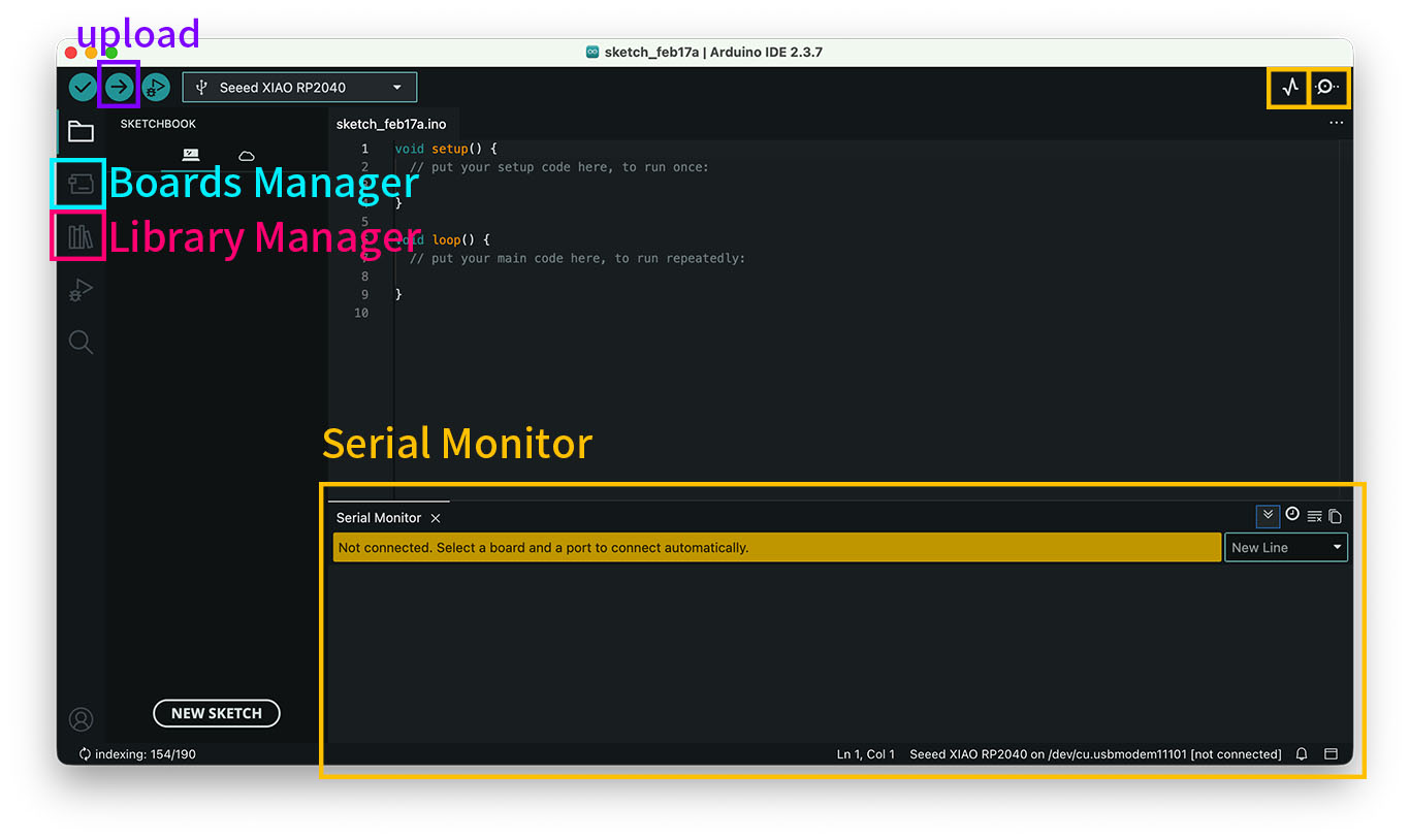
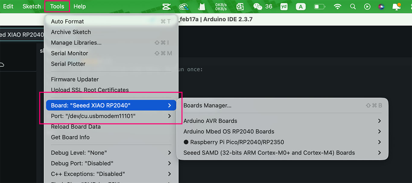
Before Upload the code to the board, we need to choose the board and port from Tools.
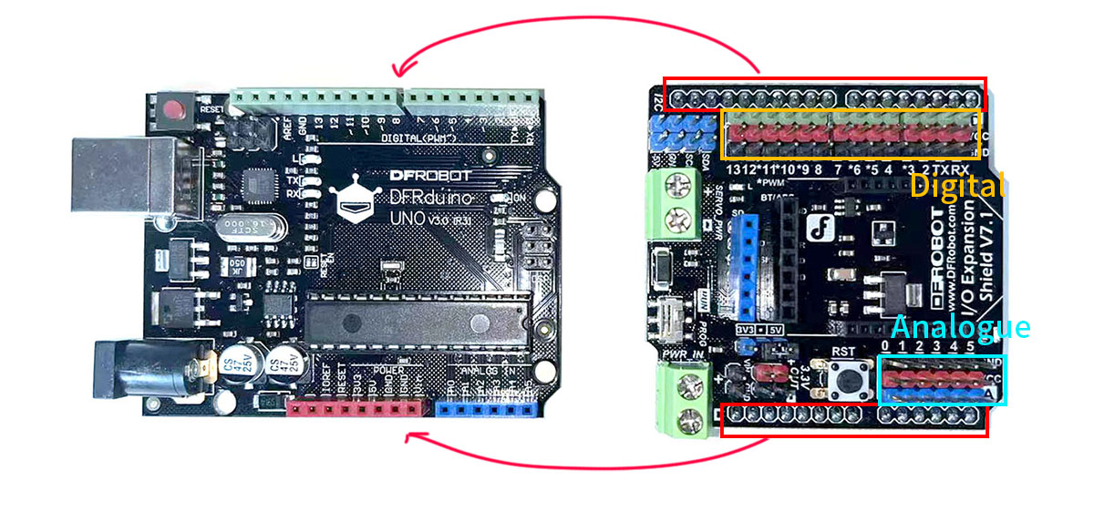
Dfrobot
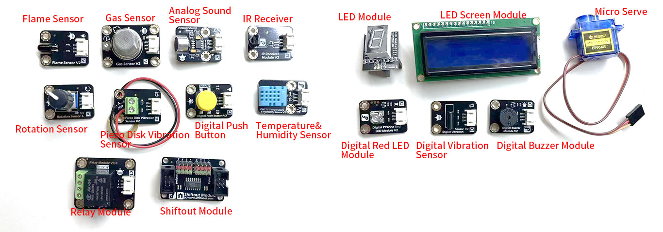
Gravity: Starter Kit for Arduino
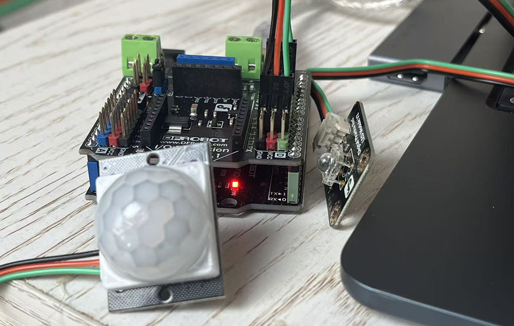
This Pack includes DFRduino UNO R3, the same as Arduino UNO, and 12 most popular and interesting electric components and sensors.
Digital pins: Signal will show on the serial monitor as 0 or 1/ on or off
Analogue pins: Signal will show on the serial monitor as 0 or 1023
This first program I try to follow the tutorial from Dfrobot, this is a sensor light. and also we can use the examples form Arduino IDE basic, Blink. The LED light will on for one second and off one second.
//sensor light
int sensorPin = 2;  //The sensor is connected to digital 2
int ledPin = 13;   //The LED is connected to digital 13
int sensorState = 0;  //The variable "sensorState" is used to store the status of the sensor
void setup() {
  pinMode(ledPin, OUTPUT);         //LED is an output device.
  pinMode(sensorPin, INPUT);      //The sensor is an input device.
}
void loop(){
  sensorState = digitalRead(sensorPin);    //Read the value of the sensor

  if (sensorState == HIGH) {       //If it is high, the LED will light up.
    digitalWrite(ledPin, HIGH);
  }
  else {                               //Otherwise, the LED will go out.
    digitalWrite(ledPin, LOW);
  }
}
int: To store integer values, int is the standard way to work with integer numbers in the code.
void setup() {

}
void loop(){

}
void: When program running, it only runs the following function definition one time and not return any value.
setup()andloop()are essential funtion for Arduino program.
setup() only runs one time, normaly include setting pinMode, Serial.begin, launch sensor.
loop() will constantly repeate until power off or reset.
(..,..): Parameter list, which iclude the type and name, different parameter divide by ,
{...}: It includes function body that runs program and logic.
void loop(){
  sensorState = digitalRead(sensorPin);    //Read the value of the sensor

  if (sensorState == HIGH) {       //If it is high, the LED will light up.
    digitalWrite(ledPin, HIGH);
  }
  else {                               //Otherwise, the LED will go out.
    digitalWrite(ledPin, LOW);
  }
}
The initial sensorState has a value = 0, then sensorState has given the value of the sensor by digitalRead(sensorPin), either HIGH or LOW
HIGH: High voltage, it's value = 1, (normally 5.5/3v)
LOW = Low voltage, it's value = 0, 0v
Conditional Control Statement
if( Conditional ){ //if condition=true
  ... // Execute this command
}
else{ // if condition=flase
  ... // Execute this command
}
Seeed Xiao
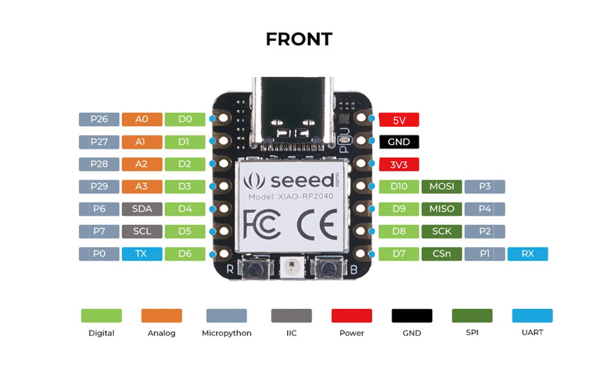
Seeed Xiao RP2040 PIN map
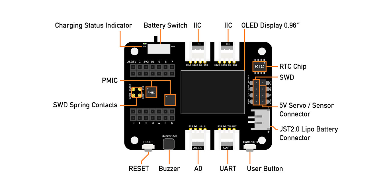
This pack includes Expansion Board and serval sensors and controllers. We need to prepare extra chip: Seeed Xiao RP2040, SAMD21, nFR52840 or ESP32.
I learn PIN MAP when I browser the Datasheet from Seeed.
Xiao Pin match the number of Chip pin, each pin has its function. Follow the map, I will know how to connect the deviecs.
If I need to connect the I2C screen, then need to choose D4 and D5, which match the I2C devices.
Base on different voltage needs, I can choose 3.3V or 5V.
AI Support
I'm using Deepseek as an AI tool to help me learn and write code while developing the device.
- Learn technical terminology: When I come across an unfamiliar sensor or pinout, I can ask the LLM to help me understand how it works.
- Plan the circuit connections: I start with a rough idea of the setup and discuss it with the LLM to refine and optimize the wiring.
- Write and test code: Once I have a functional plan, the LLM assists in generating the code, which I can then simulate using Wokwi. The generated code may not always work perfectly-it might, for example, assign the wrong input or output pins. I then adjust the code accordingly. When errors occur, I share the error messages with the LLM to help with debugging.
Individual Assignment
- [ ] Browse through the data sheet for a microcontroller
- [ ] Write and test a program for an embedded system using a microcontroller to interact (with local input &/or output devices) and communicate (with remote wired or wireless connections)
After an introduction to the Qpad in class, along with a recommendation to build something similar, I found it fascinating that we can control a white cube on a screen. As someone new to this, I'm excited to try building a similar setup myself, or experiment with comparable kits to create a controllable cube.
I bought
- Seeed Xiao RP2040,
- A pack "Starter Kit for Speed Studio XIAO"
- Some small copper sheet
1. Selecting the Board in Arduino IDE
I started by opening Arduino IDE and navigating to File > Preferences. In the "Additional Boards Manager URLs" field, I added the following link to enable RP2040 support:
https://github.com/earlephilhower/arduino-pico/releases/download/global/package_rp2040_index.json
Then I went to Tools > Board > Boards Manager, searched for "RP2040", and found the package "Raspberry Pi Pico/RP2040" by Earle Philhower. I clicked Install - but that's where the trouble began.
Note: As the Seeed Xiao rp2040 not longer been updated and fixed by official, we can't directly choose this board in the boards manager.
2. Problem: Network Timeout During Installation
It turned out the IDE was trying to download a required toolchain from GitHub, but the connection kept timing out - likely due to network instability or regional restrictions.
3.Switching to a Mobile Hotspot
After several failed attempts, I decided to try a different network environment. I disconnected from my Wi-Fi and connected my computer to a mobile phone hotspot instead.
Then I went back to Boards Manager, searched for "RP2040", and clicked Install again.
This time, the download completed smoothly without any timeout errors. The toolchain was downloaded and installed in just a couple of minutes.
4.Testing
Once the installation succeeded, I selected the correct board:
Tools > Board > Raspberry Pi RP2040 Boards > Seeed XIAO RP2040
Tools > Ports > /dev/cu.usbmodem11101
And also
Installing the Required Libraries
To drive the SSD1306 OLED screen, we need two libraries:
Adafruit SSD1306: The driver library for SSD1306/SSD1315 controllers
Adafruit GFX: The core graphics library that provides drawing and text functions
- In Arduino IDE, go to Tools → Manage Libraries.
- Search for "Adafruit SSD1306" and click Install.
- When prompted, choose "Install All" to include required dependencies (Adafruit GFX, Adafruit BusIO).
- Wait for the installation to finish.
Once finished, both libraries will be available for use in your sketches, and you're ready to start coding for the OLED display!
#include <Wire.h>
#include <Adafruit_GFX.h>
#include <Adafruit_SSD1306.h>
#define SCREEN_WIDTH 128 // OLED width(pixel)
#define SCREEN_HEIGHT 64 // OLED heigh(pixel)
#define OLED_ADDR 0x3C // Screen I2C address
// Create display object
// This object is used to control an OLED screen with the SSD1306 driver chip.
//SCREEN_WIDTH - the width of the display in pixels
//SCREEN_HEIGHT - the height of the display in pixels
//&Wire - a pointer (reference) to the I2C bus object Wire (from the Wire.h library). This tells the display library which I2C bus to use for communication.
//-1 - the reset pin number. A value of -1 means no dedicated reset pin is used (the display is either self-resetting or its reset pin is tied to VCC).
Adafruit_SSD1306 display(SCREEN_WIDTH, SCREEN_HEIGHT, &Wire, -1);
//After this line, you can call methods like display.begin(), display.clearDisplay(), and display.display() to actually use the screen.
void setup() {
Serial.begin(115200);
// Initialize OLED
if(!display.begin(SSD1306_SWITCHCAPVCC, OLED_ADDR)) {
Serial.println("SSD1306 fail!");
while(1); // Initialization failed. Program paused.
}
// clean the screen
display.clearDisplay();
// Set text properties
display.setTextSize(1); // Text size
display.setTextColor(SSD1306_WHITE); // white
display.setCursor(0, 0); // Initial coordinates
// output text
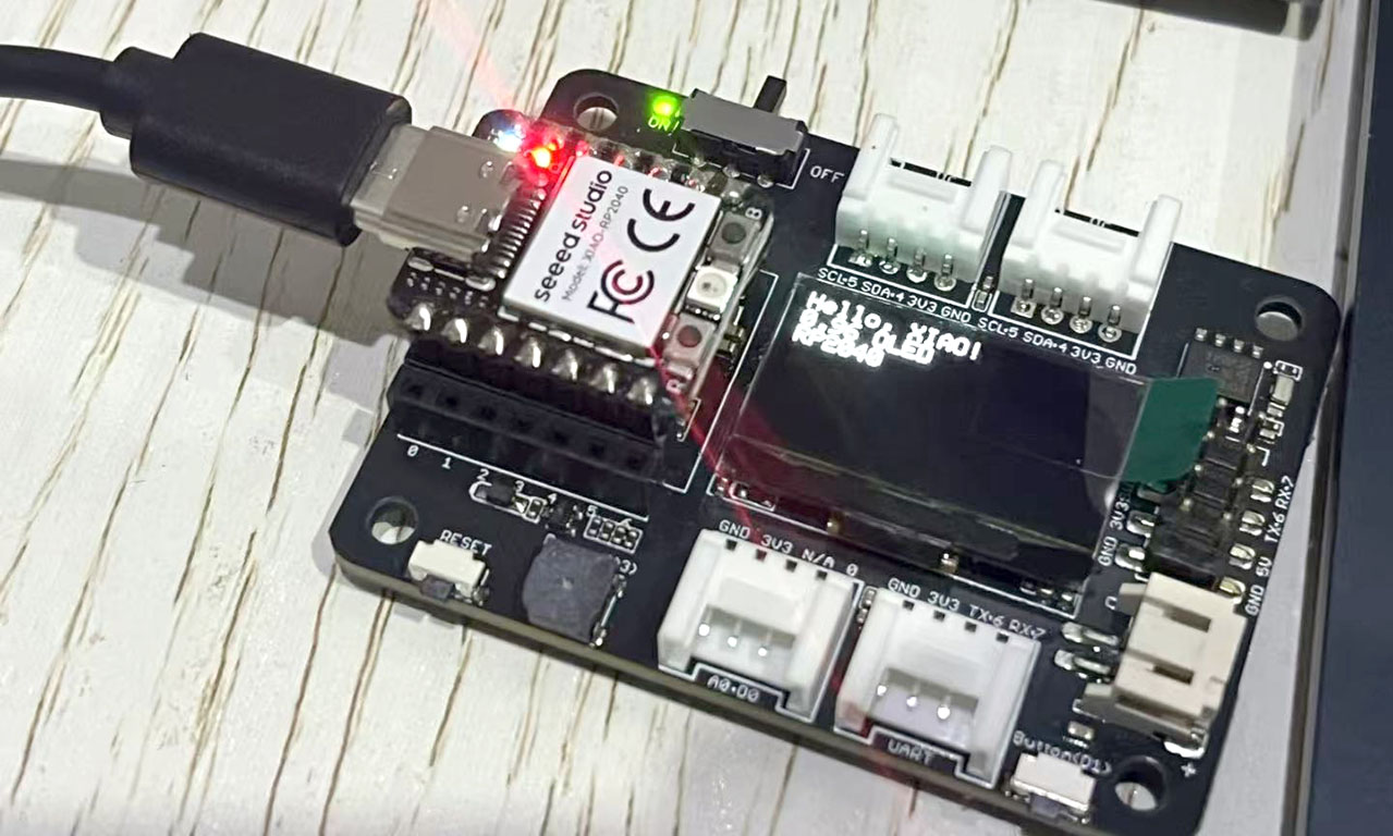
display.println("Hello, XIAO!");
display.println("0.96 OLED");
display.println("RP2040");
// Display the contents of the buffer onto the screen
display.display();
}
void loop() {
// The main loop can be left blank or additional functions can be added.
}
Library
#include: Tell the compiler to insert the content of the specified file at the current code position before compilation. If we doesn't include the specified library, when we use the function from the specified library, it will cause an error.
<Wire.h>: Used for connecting the microcontroller with various peripherals.
such as
- OLED screen
- Temperature and humidity sensor
- Barometric pressure sensor
<Adafruit_GFX.h>: Provide a unified drawing API, such as drawPixel(), drawLine(), drawCircle(), drawRect() and text display. It is a "basic library" that provides a consistent programming interface for all Adafruit displays.
<Adafruit_SSD1306.h>: An OLED screen specifically driven by the SSD1306 chip. It is responsible for the underlying I2C/SPI communication and has rewritten the drawPixel() method in the GFX library, instructing the hardware exactly how to light up each pixel.
#define: It defines a macro-a piece of code that is replaced by the preprocessor before compilation.
#define MACRO_NAME replacement_text
Following the Qpad Tetris example, I attempted to port it to my own board and replace the touch pads with the IR remote from the kit to control the bricks.
First, I tested the IR remote's responsiveness.
Connect the signal pin of the infrared receiver to A0 (physical pin 26 on the microcontroller), and verify that the IR remote is functioning properly.
Download IRremote from Libraries
#include <IRremote.hpp>

#define IR_RECEIVE_PIN  26

void setup() {
  Serial.begin(115200);
  IrReceiver.begin(IR_RECEIVE_PIN, ENABLE_LED_FEEDBACK);
  Serial.println("IR Receiver ready. Press any key...");
}

void loop() {
  if (IrReceiver.decode()) {
    Serial.print("Command: 0x");
    Serial.println(IrReceiver.decodedIRData.command, HEX);
    IrReceiver.resume();
  }
}
<IRremote.hpp>: Introduce a powerful infrared remote control library into your Arduino program. It enables your Arduino to "understand" and "send" infrared remote control signals.
-
Receive infrared signals: Read the instructions sent by infrared remote controllers (such as those for televisions and air conditioners).
-
Send infrared signals: Act as a remote control to control the infrared devices in the home.
-
Decode multiple protocols: Support the vast majority of infrared remote control protocols available on the market.
| Function | Effect |
|---|---|
| IrReceiver.begin(pin) | Initialize the receiver |
| IrReceiver.decode() | Check if the signal has been received |
| IrReceiver.decodedIRData.command | Obtain command code (8/16 bits) |
| IrReceiver.decodedIRData.address | Obtain the address code |
| IrReceiver.decodedIRData.protocol | Obtain the protocol type |
| IrReceiver.resume() | Continue to receive the next signal |
| IrReceiver.printIRResultShort(&Serial) | Print the summary results |
| IrReceiver.printIRSendUsage(&Serial) | Print and send the code that generates this signal |
Serial.begin(115200);: 115200 is baud rate.
Baud rate: The baud rate refers to the transmission rate, and its unit is bps (bits per second). For example, 115200 indicates that 115200 binary bits are transmitted per second.
Serial communication has a series of established standard baud rates, such as 300, 600, 1200, 2400, 4800, 9600, 14400, 19200, 28800, 38400, 57600, 115200, etc.
-
Slower rates (such as 9600): More stable, with strong anti-interference capability, but slower transmission speed. Suitable for scenarios with small data volume.
-
Faster rates (such as 460800, 921600): Require hardware support (some Arduino boards cannot reach such high speeds), and are prone to interference causing errors. Generally used in scenarios requiring high-speed transmission.
Note: You can choose any standard baud rate as needed, but it is essential to ensure that all communication devices are set to the same settings.
ENABLE_LED_FEEDBACK is a Constant from DISABLE_LED_FEEDBACK or "false".
HEX is a constant used to specify that the Serial.print() function outputs numerical values in hexadecimal format.
0x: This is done to add the common hexadecimal prefix 0x before the output values, making the output more clear and easier to read.
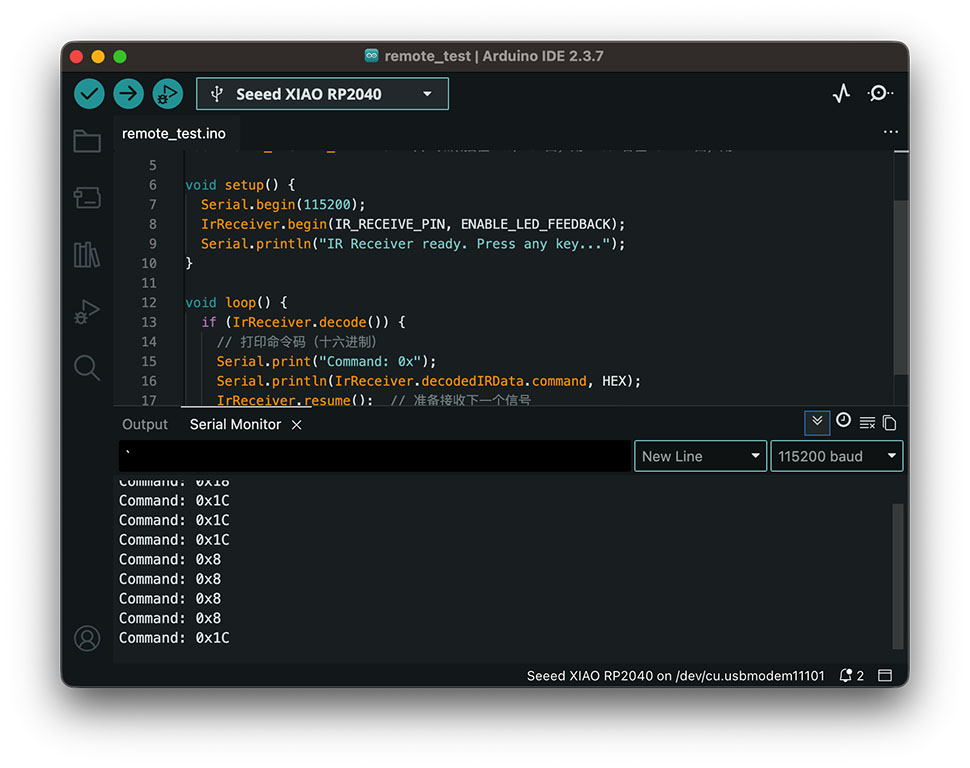
Set the Serial Monitor to a baud rate of 115200. After uploading the program, pressing a key on the remote will display the corresponding signal in the Serial Monitor. This allows you to map each key to its signal code, which can later be used as a reference in the program.
Tetris Seeed_xiao_rp2040
#include <Arduino.h>
#include <U8g2lib.h>
#include <Wire.h>
#include <IRremote.hpp>
<Arduino.h>: This library includes all the standard Arduino functions.
<U8g2lib.h>: It provides a unified API for controlling screen drawing, supporting various interfaces such as I2C, SPI, and parallel, as well as dozens of common display controllers (such as SSD1306, SH1106, ST7920, etc.).
U8G2_SSD1306_128X64_NONAME_F_HW_I2C u8g2(U8G2_R0, U8X8_PIN_NONE);
U8G2_SSD1306_128X64_NONAME_F_HW_I2C is a predefined class (constructor) in U8g2 that specifies the display type: SSD1306 driver, 128x64 resolution, generic model, full framebuffer, and hardware I2C communication.
u8g2 is a name for this screen.
U8G2_R0 sets the screen rotation to 0° (no rotation). Alternatives: U8G2_R1, U8G2_R2, U8G2_R3 for 90°, 180°, 270°.
U8X8_PIN_NONE indicates that no reset pin is used (common on many OLED modules). If a reset pin is needed, you would pass the actual pin number instead.
// = Infrared receiving pin =

#define IR_RECEIVE_PIN  26

// = Remote control button mapping (base on previous test) =

#define KEY_LEFT    0x8   // move left
#define KEY_RIGHT   0x5A   // move right
#define KEY_DOWN    0x52   // down
#define KEY_ROTATE  0x18   // rotate
#define KEY_A       0x42   // drop (A)
#define KEY_B       0x1C   // pause (B)
#define KEY_RESTART 0x16  // restart

// Used to store the currently pressed key (for simulating touch state)
// enumeration method to set a meaningful name
static const uint8_t NUM_KEYS = 7;
enum KeyIndex {
  T_LEFT = 0,
  T_RIGHT = 1,
  T_DOWN = 2,
  T_ROT = 3,
  T_A = 4,
  T_B = 5,
  T_RESTART = 6
};

// Touch state simulation (using the original variable name, updated by infrared)
bool pin_touched_now[NUM_KEYS]  = { false };
bool pin_touched_past[NUM_KEYS] = { false };

struct Piece;  //define a structure. A structure is a user-defined data type that groups together variables of different types under a single name, making it easier to manage related data.
// Utility function (adopting the original code)
bool touchHeld(int idx) { return pin_touched_now[idx]; }
bool touchPressed(int idx) { return pin_touched_now[idx] && !pin_touched_past[idx]; }
Macro: A macro is a preprocessor text substitution rule defined by #define in C/C++. It is processed before compilation, replacing the macro name with the specified text. Key Characteristics
-
Pure text replacement: No type checking, no memory allocation
-
Handled at preprocessing stage: Macros don't exist at runtime
-
Can contain any text: Numbers, expressions, code snippets
bool is a data type in C/C++ used to represent Boolean values-logical true or false.
// = TETRIS Core configuration =
//size and layout
static const int W = 10; // board width (columns)
static const int H = 20; // board heigh (rows)
static const int CELL_W = 6; // cell width
static const int CELL_H = 3; // cell heigh
static const int ORG_X = 2; // x original
static const int ORG_Y = 2; // y original
static const int UI_X = ORG_X + W * CELL_W + 6; // the UI starts from 6 times columns + 6 pixel
uint8_t board[H][W]; // 2D array, type name [y:rows] [x:columns];
struct Piece {
int type; // 0..6
int rot; // 0..3
int x;
int y;
};
Piece cur, nextP;
bool paused = false;
bool gameOver = false;
uint32_t lastFall = 0; //duration
uint32_t fallInterval = 550; //
uint32_t score = 0;
uint16_t lines = 0;
uint8_t level = 1;
// 7 tetrominós x 4 rotaciones
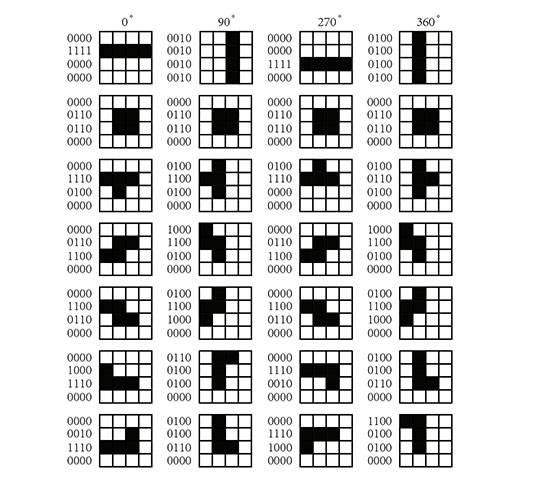
const uint16_t TETRO[7][4] = {
{ 0x0F00, 0x2222, 0x00F0, 0x4444 }, // I
{ 0x0660, 0x0660, 0x0660, 0x0660 }, // O
{ 0x0E40, 0x4C40, 0x4E00, 0x4640 }, // T
{ 0x06C0, 0x8C40, 0x06C0, 0x8C40 }, // S
{ 0x0C60, 0x4C80, 0x0C60, 0x4C80 }, // Z
{ 0x08E0, 0x6440, 0x0E20, 0x44C0 }, // J
{ 0x02E0, 0x4460, 0x0E80, 0xC440 } // L
};
{ 0x0F00, 0x2222, 0x00F0, 0x4444 }
For example of This Hexadecimal code it repesent 4 rotation:
0°:0F00 = 0000,1111,0000,0000
90°:2222 = 0010,0010,0010,0010
...
Matrix
// RNG(Random Number Generator)
uint32_t rngState = 0x12345678;
uint32_t xorshift32() {
  uint32_t x = rngState;
  x ^= x << 13;
  x ^= x >> 17;
  x ^= x << 5;
  rngState = x;
  return x;
}
int rand7() { return (int)(xorshift32() % 7); }
XOR (exclusive OR) is a fundamental logical operation that outputs true (1) only when the two inputs differ. If the inputs are the same, the output is false (0). Normally use ^ to represent.
(initial value) rngState = 0x12345678 = 0001 0010 0011 0100 0101 0110 0111 1000
uint32_t xorshift32() {
  uint32_t x = rngState;
  x ^= x << 13;
  x ^= x >> 17;
  x ^= x << 5;
  rngState = x;
  return x;
}
The Xorshift algorithm is a classic method for efficiently generating pseudo-random numbers.
<< and >> operators perform bitwise shifts on integer values. They move the bits of a number left or right by a specified number of positions.
% is the modulo operator. xorshift32() % 7 takes a large random number (0 to 4294967295) and maps it to a value between 0 and 6, corresponding to the seven Tetromino types.
// = Collision detection and block manipulation =
//
bool cellInMask(uint16_t mask, int cx, int cy) {
  int bit = 15 - (cy * 4 + cx);
  return (mask >> bit) & 1;
}
& Bitwise AND: The result has a 1 in each bit position where both operands have 1; otherwise 0.
&&Logical AND: Returns "true" only if both operands are true; otherwise "false"
CellinMaxk function that help us to find out whether cell has value or not.
mask store a 16bit number, then move to the bit position and caculate AND 1, if this position is 1 then ruturn 1, otherwise 0.
bool collides(const Piece &p, int nx, int ny, int nrot) {
  uint16_t m = TETRO[p.type][nrot & 3];
  for (int cy = 0; cy < 4; cy++) {
    for (int cx = 0; cx < 4; cx++) {
      if (!cellInMask(m, cx, cy)) continue;
      int bx = nx + cx;
      int by = ny + cy;
      if (bx < 0 || bx >= W || by >= H) return true;
      if (by >= 0 && board[by][bx]) return true;
    }
  }
  return false;
}

void stampPiece(const Piece &p) {
  uint16_t m = TETRO[p.type][p.rot];
  for (int cy = 0; cy < 4; cy++) {
    for (int cx = 0; cx < 4; cx++) {
      if (!cellInMask(m, cx, cy)) continue;
      int bx = p.x + cx;
      int by = p.y + cy;
      if (by >= 0 && by < H && bx >= 0 && bx < W) board[by][bx] = 1;
    }
  }
}

int clearLines() {
  int cleared = 0;
  for (int y = H - 1; y >= 0; y--) {
    bool full = true;
    for (int x = 0; x < W; x++) if (!board[y][x]) { full = false; break; }
    if (full) {
      cleared++;
      for (int yy = y; yy > 0; yy--) {
        for (int x = 0; x < W; x++) board[yy][x] = board[yy - 1][x];
      }
      for (int x = 0; x < W; x++) board[0][x] = 0;
      y++; // re-check
    }
  }
  return cleared;
}

void updateLevelSpeed() {
  level = 1 + (lines / 10);
  int base = 550 - (int)(level - 1) * 40;
  if (base < 120) base = 120;
  fallInterval = (uint32_t)base;
}

void spawnNext() {
  cur = nextP;
  cur.rot = 0;
  cur.x = 3;
  cur.y = -1;

  nextP.type = rand7();
  nextP.rot = 0;

  if (collides(cur, cur.x, cur.y, cur.rot)) {
    gameOver = true;
  }
}

void resetGame() {
  memset(board, 0, sizeof(board));
  paused = false;
  gameOver = false;
  score = 0;
  lines = 0;
  level = 1;
  fallInterval = 550;

  rngState ^= micros();
  nextP.type = rand7();
  spawnNext();
  lastFall = millis();
}
Download