Assemble
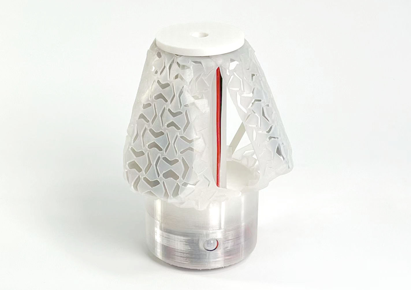
These are all parts of the lamp.
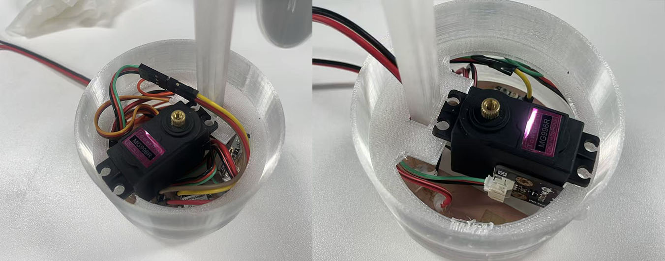
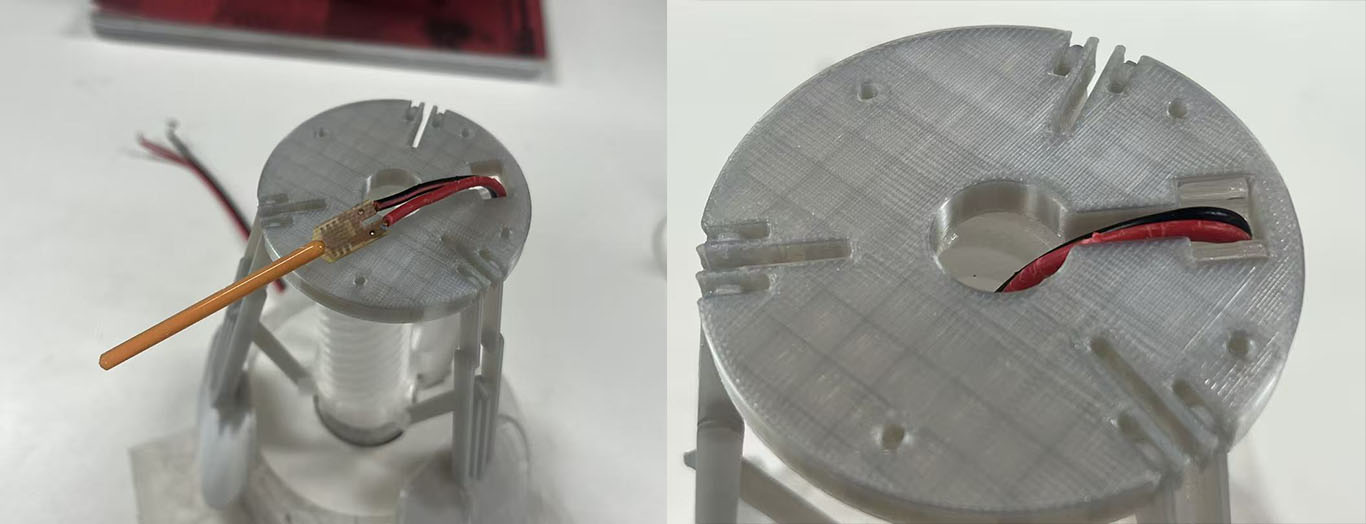
The PCB is secured to the base with tape, while the central motor helps lock its position. The PIR sensor rests against the motor and extends through the side hole in the base.
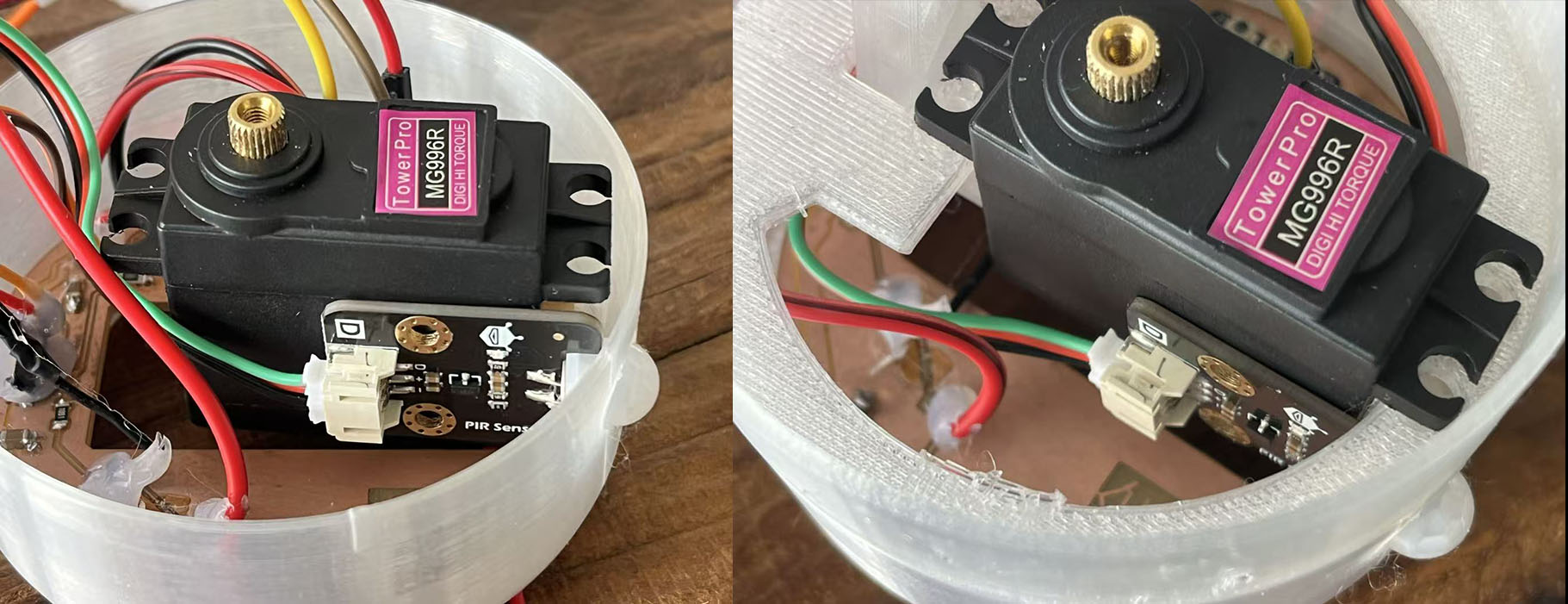
Trimming the overly long wire. Because of the self-locking structure, the motor will be locked in the fixed position when it is positioned at the positioning point.
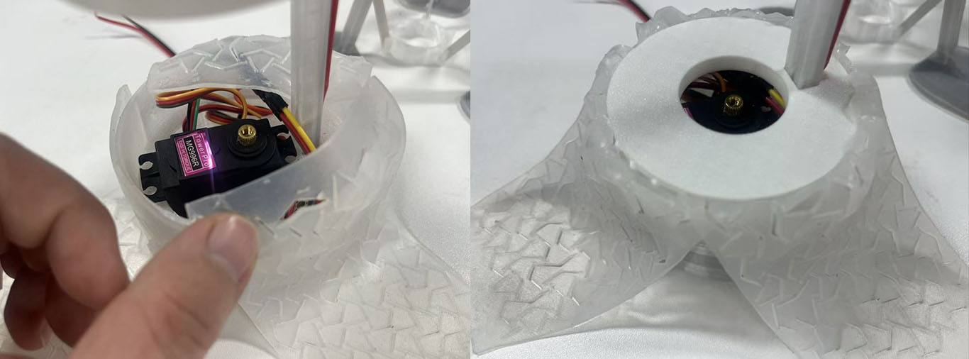
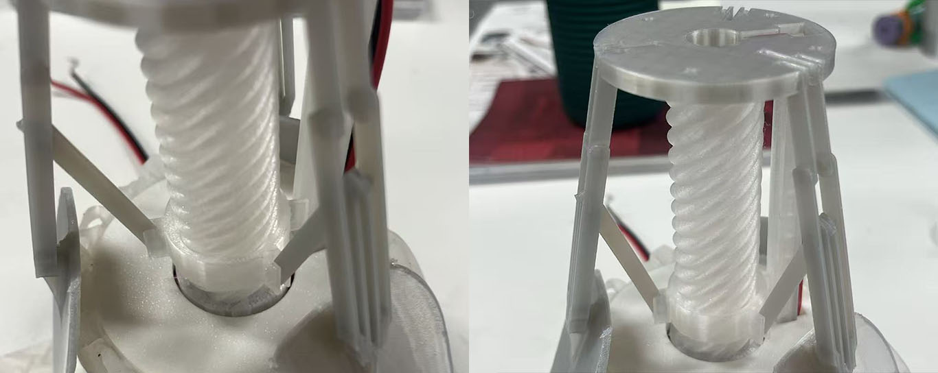
On top of the motor, a skin locker is installed to cap the motor and secure the skin in place using the embossed pattern.
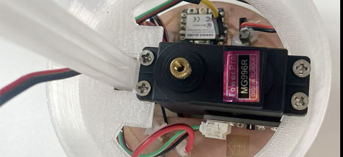 Screw four M3 screws in the reserved holes to fix the motor
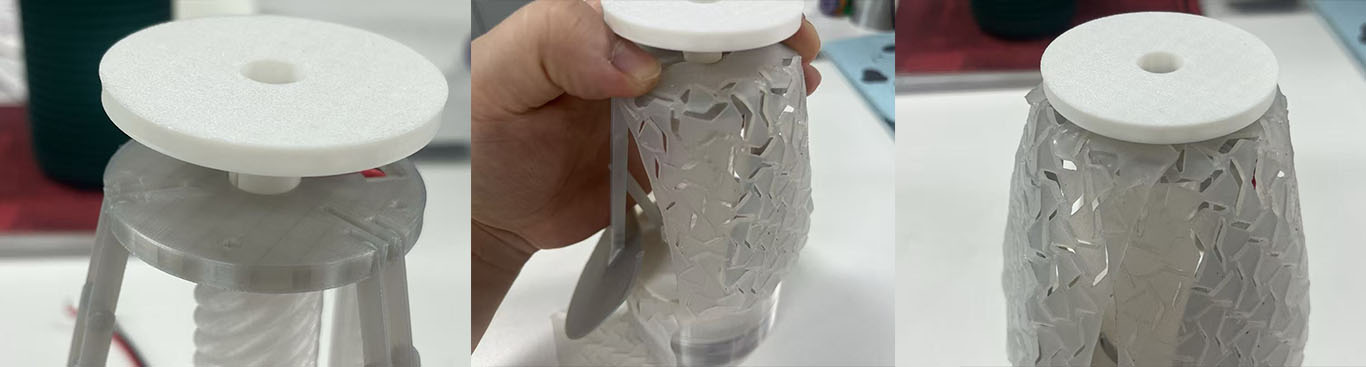
When capping it, place the skin on the edge so that it slides smoothly into the gap and locks securely.
When connecting the slider and the linkage, make sure the fixing block is on the same side as the empty slot.
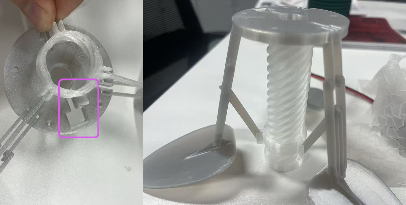
Go up along the fixed pole, and then insert the lamp head into the hollow of the twist.
Ensure the fixing block of the slider is inserted into the slot on the fixed pole.
The final step is to lock the top edge of the skin. Place the three pieces of skin on the plate, then press and tighten the cap. The skin will be secured in place
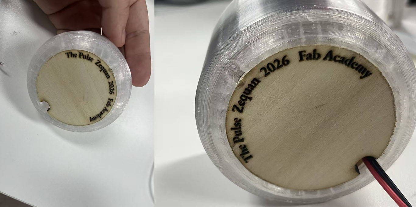
On the bottom, inserted a logo cap to close this object.