
Week 09: Input Devices
Assignments:
Group Assignment
- Probe an input device(s)’s analog levels and digital signals
- Document your work to the group work page and reflect on your individual page what you learned
Individual Assignment
- Measure something: add a sensor to a microcontroller board that you have designed and read it.
Things to Complete This Week
- Explore and test different sensors
- Document process
- Work on Final Project PCB!!!
Here is my schedule for this week.
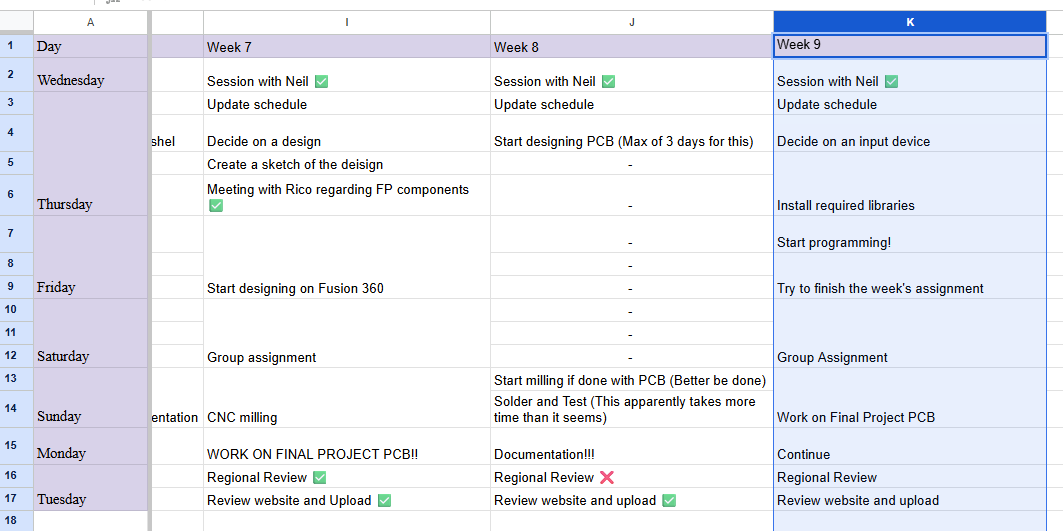
Here is the link to my schedule
Group Assignment
You can access our group assignment here.
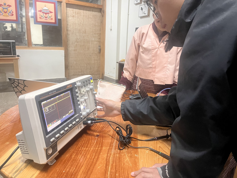
This week, we made use of the oscilloscope to observe the signals produced by the SEN-14262 Sound Sensor (Input device). In this assignment, we probed the sensor to see both its analog levels and digital signals. By doing this, we could observe how the device reacts to real-world changes and how it sends information to the board. I was able to properly understand the difference between continuous analog signals and simple on/off digital signals.
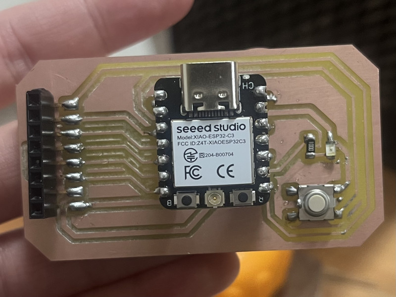
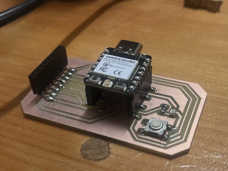
Individual Assignment
This week, I used the board that I designed during Electronics Production week to test and evaluate three different sensors: the HC-SR04 Ultrasonic Sensor, SEN-14262 Sound Sensor, and a DHT11 Temperature and Humidity Sensor.
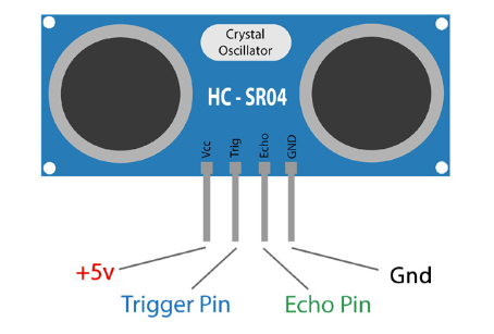
1. HC-SRO4 Ultrasonic Sensor
An ultrasonic sensor is a device that measures the distance to an object using high frequency sound waves 🔊. I will be using this for my Final Project as well.
It operates with a voltage supply of 3.3–5 V and has four pins: VCC for power, GND for ground, TRIG for sending a short ultrasonic pulse, and ECHO for receiving the reflected pulse.
How it works?
The Ultrasonic Sensor sends out a short ultrasonic pulse into the air, which travels until it hits an object and reflects back toward the sensor. The sensor then detects this returning echo and calculates how long the sound takes to travel to the object and back.
Since sound moves at a known speed in air, the sensor can use this time to determine the distance to the object, dividing by two to account for the round trip. A faster return means the object is closer, while a slower return indicates it is farther away.
Distance = (Time × Speed of Sound) / 2
Here are the connections I made:
| HC-SR04 Pin | Connect to XIAO Pin | Type |
|---|---|---|
| VCC | 5V | Power |
| GND | GND | Ground |
| Trig | GPIO 4 | Digital Output |
| Echo | GPIO 5 | Digital Input |
I asked ChatGPT to generate a code for my board and this was the prompt I used: Can you generate a code for an ultrasonic sensor that measures distance and makes an LED blink if an obstacle is too close?
int trigPin = 4;
int echoPin = 5;
int ledPin = 8; // built-in LED (XIAO ESP32-C3)

long duration;
float distance;

void setup() {
  pinMode(trigPin, OUTPUT);
  pinMode(echoPin, INPUT);
  pinMode(ledPin, OUTPUT);

  Serial.begin(9600);
}

void loop() {
  // Send ultrasonic pulse
  digitalWrite(trigPin, LOW);
  delayMicroseconds(2);

  digitalWrite(trigPin, HIGH);
  delayMicroseconds(10);
  digitalWrite(trigPin, LOW);

  // Read echo time
  duration = pulseIn(echoPin, HIGH);

  // Convert to distance (cm)
  distance = duration * 0.034 / 2;

  Serial.print("Distance: ");
  Serial.print(distance);
  Serial.println(" cm");

  // 🚨 If object is close → blink LED
  if (distance > 0 && distance < 20) { // change 20cm if you want
    digitalWrite(ledPin, HIGH);
    delay(200);
    digitalWrite(ledPin, LOW);
    delay(200);
  } else {
    digitalWrite(ledPin, LOW);
  }

  delay(100);
}
What does the code do?
The ultrasonic sensor measures the distance to an object in front of it and uses the built-in LED (on the board) as an alert. It continuously sends a short pulse through the TRIG pin and listens for the returning echo on the ECHO pin. If the object is closer than 20 cm, the LED blinks on and off to signal an obstacle, and if the object is farther away, the LED stays off.
Here are the results! 😄
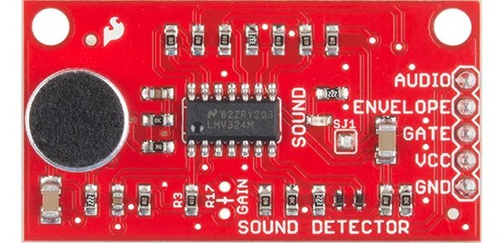
2. SEN-14262 Sound Sensor
The SEN-14262 sound sensor is a small module designed to detect sound in the environment and output both analog and digital signals.
It operates with a voltage supply of 3.3–5 V and has five pins: VCC for power, GND for ground, AUDIO for the raw analog waveform of the sound, ENVELOPE for a smoothed analog signal representing overall loudness, and GATE for a digital signal that goes HIGH when the sound exceeds a set threshold.
How does it work?
The sound sensor detects air vibrations using a microphone, converting them into an electrical signal. The AUDIO pin shows the full sound wave, the ENVELOPE pin shows a smoothed version of the loudness signal, and the GATE pin goes HIGH when a sound is loud enough. This lets a microcontroller detect both the presence and the intensity of the sound.
Here are the connections I made:
| Sound Sensor Pin | Connect to XIAO Pin | Type |
|---|---|---|
| VCC | 3.3V | Power |
| GND | GND | Ground |
| Gate | GPIO 4 | Digital |
| Envelope | GPIO 6 | Analog |
| Audio | GPIO 5 | Analog |
I asked ChatGPT to generate a code for my board (Again 😅) and here was the prompt I used: Can you write a program for a SEN-14262 sound sensor that uses the Gate pin to detect sound and blink an LED when sound is detected?
int gatePin = 4;   // Gate pin
int ledPin = 8;    // LED

void setup() {
  pinMode(gatePin, INPUT);
  pinMode(ledPin, OUTPUT);
  Serial.begin(9600);
}

void loop() {
  int state = digitalRead(gatePin);

  if (state == HIGH) {
    Serial.println("Sound detected! Blinking LED🚨");

    for (int i = 0; i < 1; i++) {
      digitalWrite(ledPin, HIGH);
      delay(200); // LED ON
      digitalWrite(ledPin, LOW);
      delay(200); // LED OFF
    }
  } else {
    Serial.println("No sound detected 🤐");
    digitalWrite(ledPin, LOW); // keep LED off when quiet
  }

  delay(200); // small delay to stabilize readings
}
What does the code do?
This code uses the sound sensor’s Gate pin to check if a loud sound is detected. If sound is detected (HIGH), it prints a message in the Serial Monitor and briefly blinks an LED. If no sound is detected, it prints a different message and keeps the LED off. It repeats this process continuously, allowing the system to react to sounds in real time.
Note: In my case, I only had to use the Gate pin and there was actually no need for the Audioand Envelope pin 🫠. But the Audio pin could be used to provide the raw output from the microphone and the envelope pin could be used for measuring the actual loudness of the sound.Here is how it turned out 😄
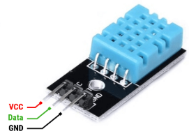
3. DHT11 Sensor
A DHT11 sensor is a device that is used to measure temperature🌡️ and humidity (moisture in the air)💧.
It operates with a voltage supply of 3.3–5 V and has three pins: VCC for power, GND for ground, and DATA for digital communication. The sensor measures temperature and humidity and then sends the readings as a digital signal through the DATA pin, which can be read by a microcontroller.
How does it work?
The DHT11 sensor works by measuring temperature and humidity using internal elements and then converting those readings into a digital signal. Inside the sensor a humidity sensing component detects moisture in the air, while a thermistor measures temperature. The sensor processes these values with a built-in microcontroller and sends the data as a digital signal through the DATA pin. A microcontroller reads this signal at regular intervals to obtain the temperature and humidity values.
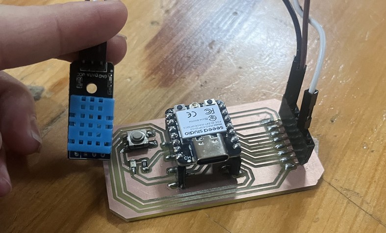
This is how I connected the sensor to my board:
| DHT Pin | Connect to XIAO ESP32-C3 | Type |
|---|---|---|
| VCC | 3.3V | Power |
| GND | GND | Ground |
| DATA | GPIO 4 | Digital |
I asked ChatGPT to generate a code for my board (Againnnnnn) and here's the prompt I used:Can you give me a code for a DHT11 sensor on pin 4 to print temperature and humidity?
#include <DHT.h>
#define DHTPIN 4        // GPIO 4
#define DHTTYPE DHT11   // change to DHT22 if you have that

DHT dht(DHTPIN, DHTTYPE);

void setup() {
  Serial.begin(115200);
  Serial.println("🌡️💧 DHT Sensor Test 💧🌡️");
  dht.begin();
}

void loop() {
  float humidity = dht.readHumidity();
  float temperature = dht.readTemperature(); // Celsius

  if (isnan(humidity) || isnan(temperature)) {
    Serial.println("⚠️ Failed to read from DHT sensor!");
    delay(2000);
    return;
  }

  Serial.print("🌡️ Temp: ");
  Serial.print(temperature);
  Serial.print(" °C  |  💧 Humidity: ");
  Serial.print(humidity);
  Serial.println(" % 🌿");

  delay(2000); // DHT needs ~2 seconds between readings
}
How does the code work?
This code makes a DHT11 sensor tell the microcontroller what the air is like. When you power it up, it starts talking to the sensor and sets up a way to show info on your computer. Every 2 seconds, it checks how hot/cold it is and how humid the air is. If the sensor messes up or can’t give a reading, it shows a warning instead of random numbers. Otherwise, it prints the temperature in °C and humidity in %
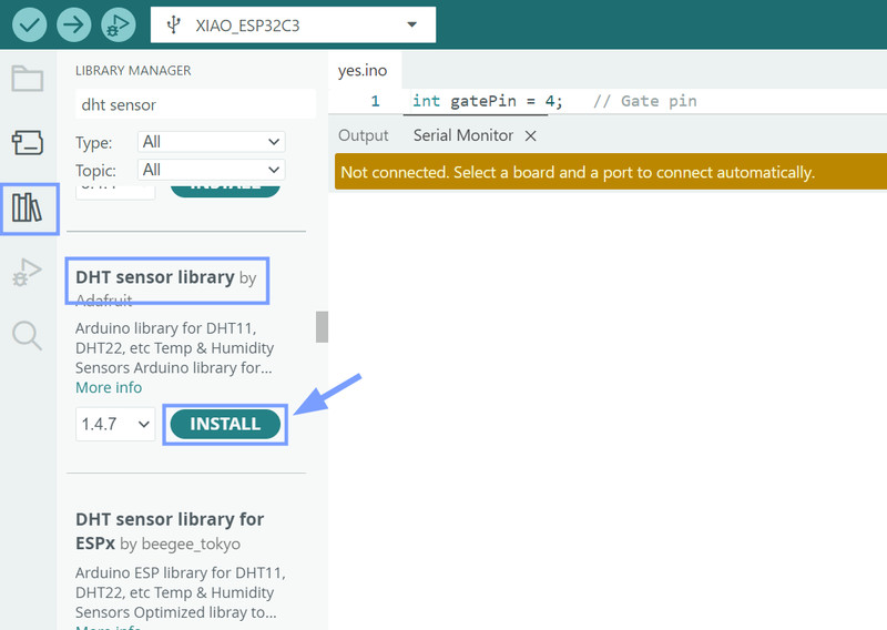
For the DHT11 Sensor, I had to download the DHT sensor library by Adafruit.
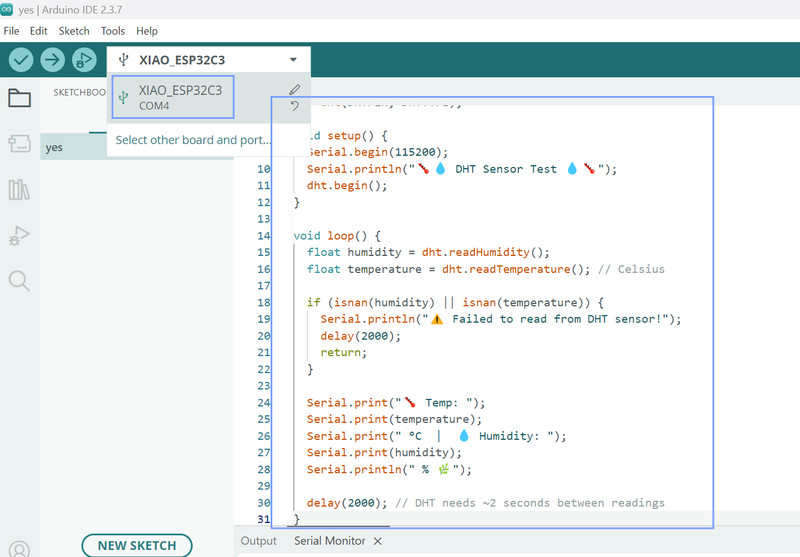
Next I pasted my code, and selected my port then board.
Here are the results! 🥳🎊
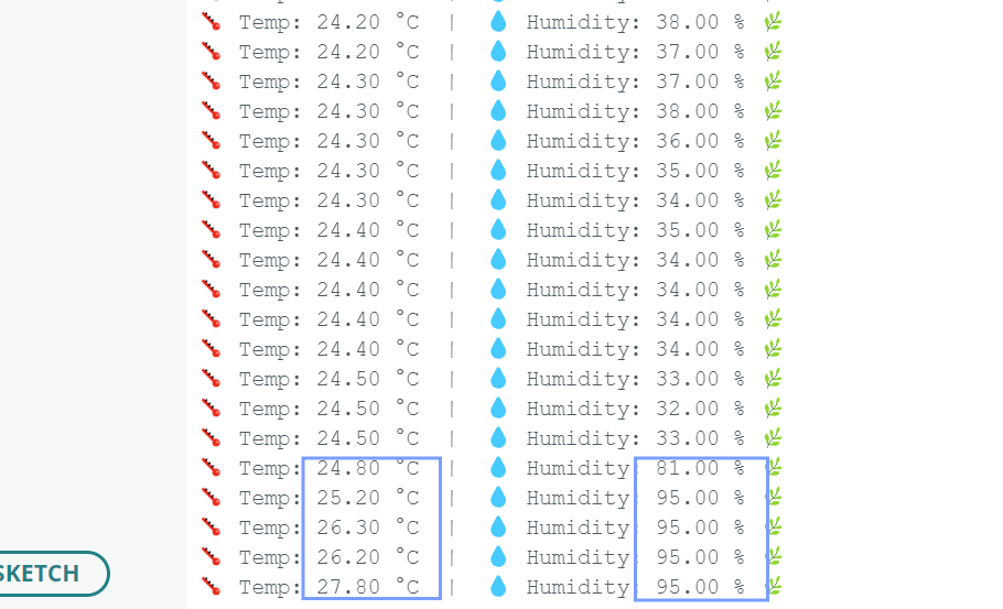
Here you can see how when I exhale near the sensor, both the temperature and humidity go up ☝️.
I feel like it was a really fun week. I was able to check out a bunch of sensors and was also able to learn a lot about how each one works. This week, I was amazed at how such small devices could have so many powerful functions (It's actually so crazy to think about) 😮.