
Week 07: Computer Controlled Machining
Assignments:
Group Assignment
- Do your lab’s safety training
- Test runout, alignment, fixturing, speeds, feeds, materials, and toolpaths for your machine
- Document your work to the group work page and reflect on your individual page what you learned
Individual Assignment
- Make (design+mill+assemble) something big (~meter-scale)
Things to Complete This Week
- Decide on what to design
- Document design process of the object
- Learn how to use the CNC machine
- Include design files!
Here is my schedule for this week.
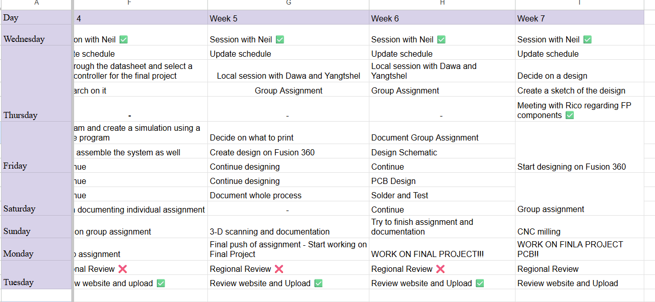
Here is the link to my schedule
Group Assignment
You can access our group assignment here.
What is CNC?
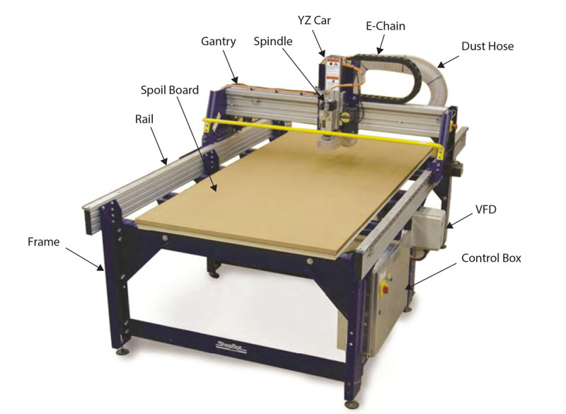
CNC means Computer Numerical Control. It is a manufacturing process where machines are controlled by a computer to cut, shape, or carve materials. Instead of operating the machine manually, a digital design is created using CAD software and then converted into instructions that the machine follows automatically. This allows the machine to move the cutting tool with high precision 🤠The CNC machine that we have in our lab is the ShopBot PRS.
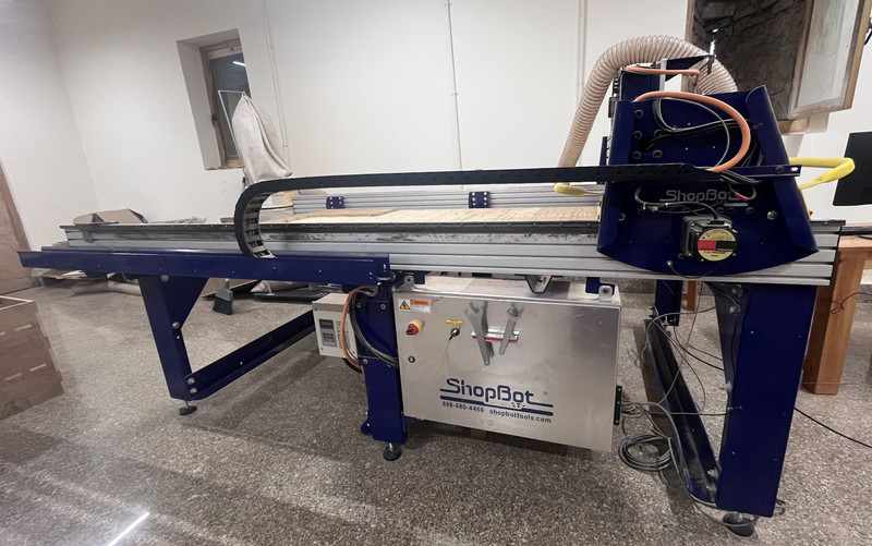
Workspace: 2400 mm × 1220 mm
Speed: We used a spindle speed of 10000 RPM to cut our design.
Software: The machine is operated using ShopBot Control Software.
Fixture: The material is fixed to the machine bed using clamps so it does not move during cutting.
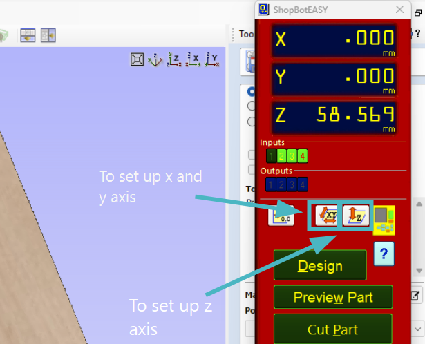
Setting Origins: We use ShopBot 3 to set the machine origins. Proximity sensors help set the X and Y axes, while the Z axis is set manually using the zeroing plate.
Individual Assignment
Backpack Holder Design
For this week's assignment, I wanted to design a Backpack Holder for my final project (The Smartfollow Backpack).
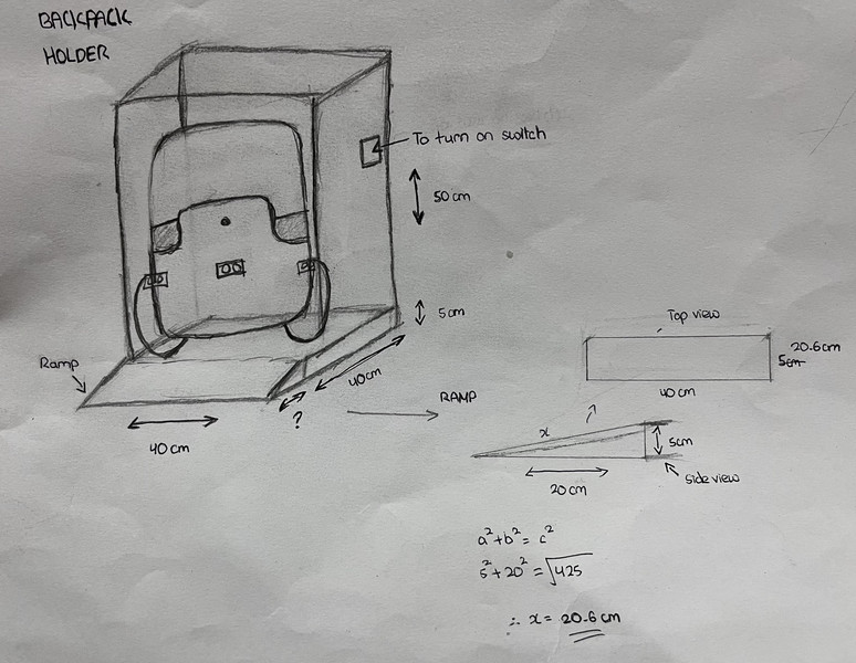
Here is a sketch of how it's supposed to look.
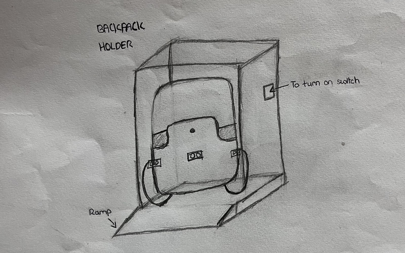
Here are the dimensions of the holder. As for the ramp, I made use of the pythagoras theorum to get the length of the plank that I'll be using and I got 20.6cm.
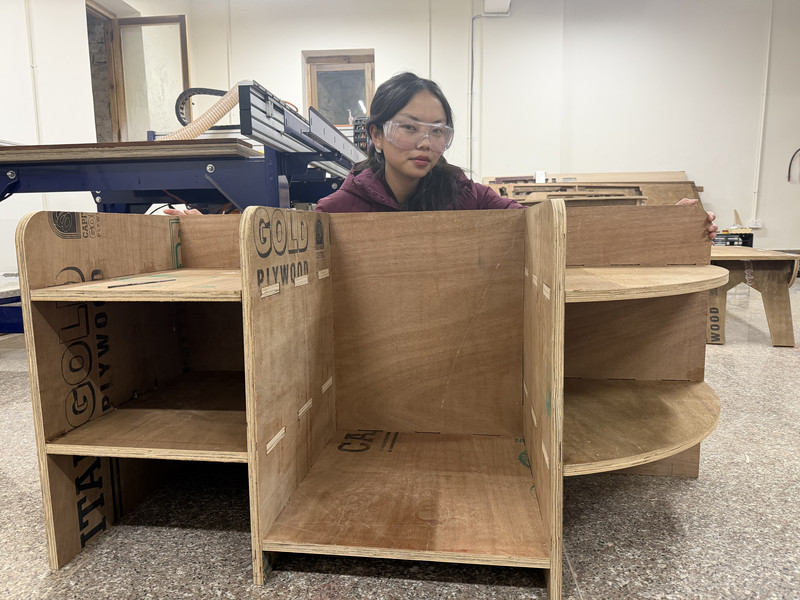
HEROSHOT!!!
Fusion 360
For the design process, I will be using Fusion 360 because it is the software that I am most familiar with. I have also used it for several projects in the past. And although I'm not entirely an expert at it, I feel like this will allow me to work smoothly ( •̀ .̫ •́ )✧ Here are the steps that I followed:
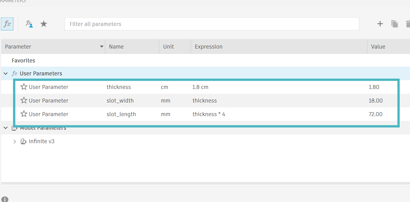
Here are the parameters that I used:
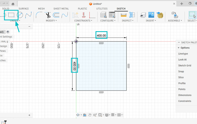
1. I first started by creating a sketch of a 40cm x 40cm square.
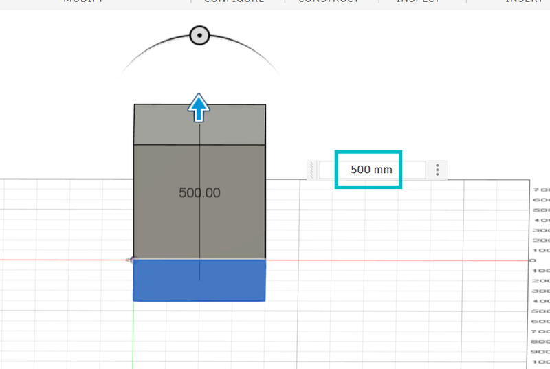
2. I then extruded the shape by 50 cm.
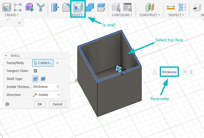
3. I used the shell tool to create this hollow structure. For this, I used the thickness parameter.
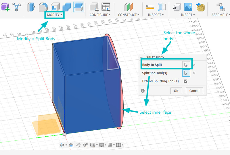
4. Next I used the split tool to split the body into 5 parts.
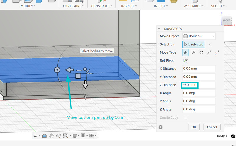
5. I deleted one side and moved the bottom part up by 5cm.
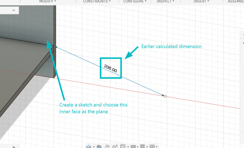
6. After that, I created a sketch and chose the interior face as the plane. I then used the earlier calculated dimension of the hypotenuse and created a line using that.
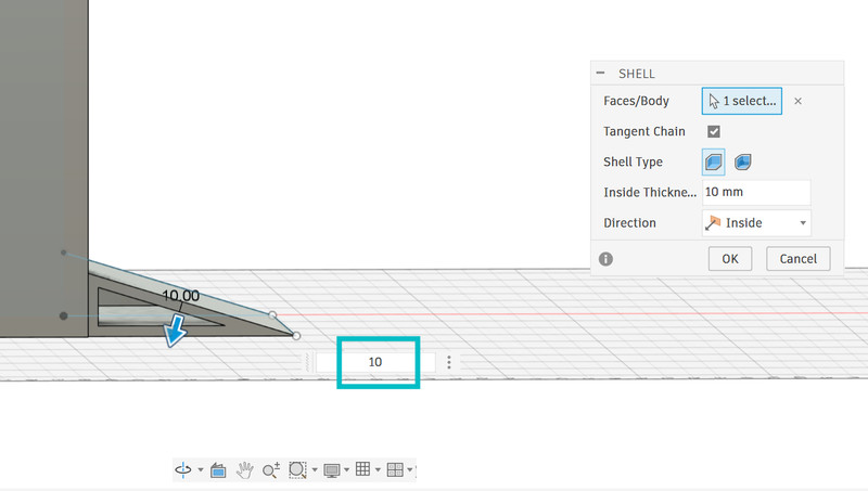
7. I extruded the triangle and used the shell tool to make it hollow.
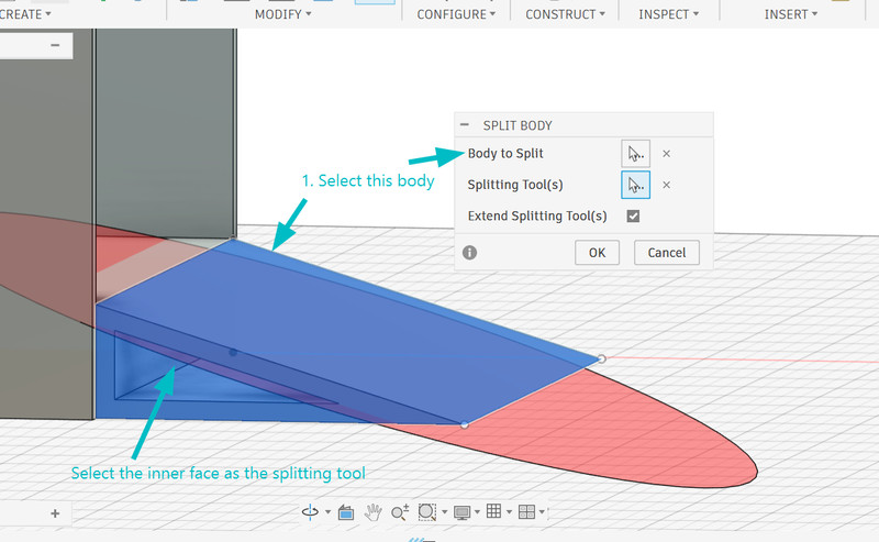
8. I then split the body because the only part I need is the hypotenuse.
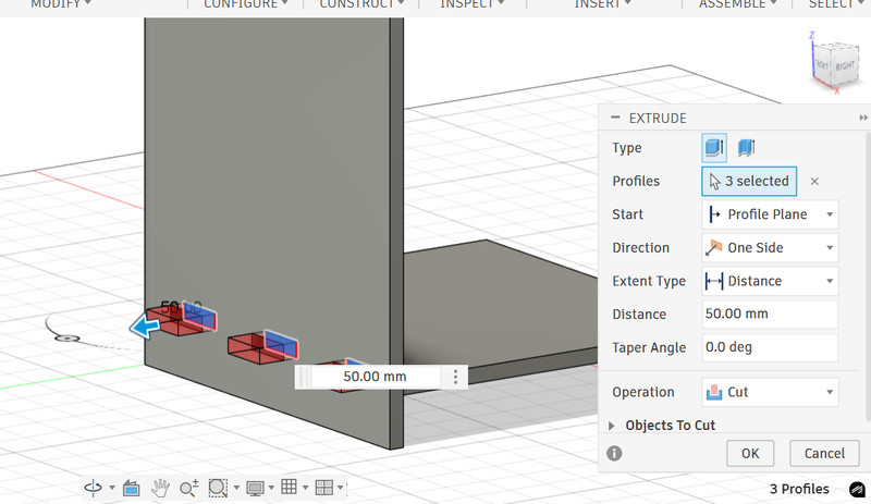
9. To create the joint slots, I first started by drawing a sketch with three rectangles. After that I selected the three rectangles and did an extrude cut of 5cm (I don't think the value matters as long as it cuts all the way through)
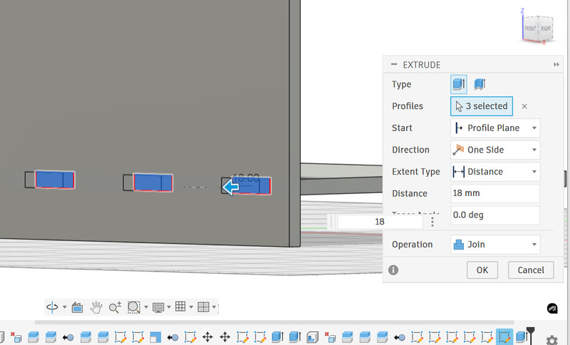
10. After that I used the thickness parameter and extruded the rectangles. I made the mistake of t=not hiding the side body and the operation was set to "Join." Make sure to hide the side body first and then extrude, this way you can keep the extrude operation as "Join" only.
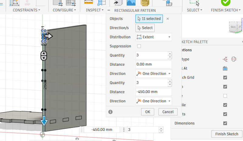
11. I also decided to simultaneously create finger joints as I go. For this, I created a rectangular sketch and used the rectangular pattern tool to create two more of the same rectangular sketches. Similar to the slot joints, I first did an extrude cut and then extrdued the rectangles using the thickness parameter.
12. I did the same for all the other joints.
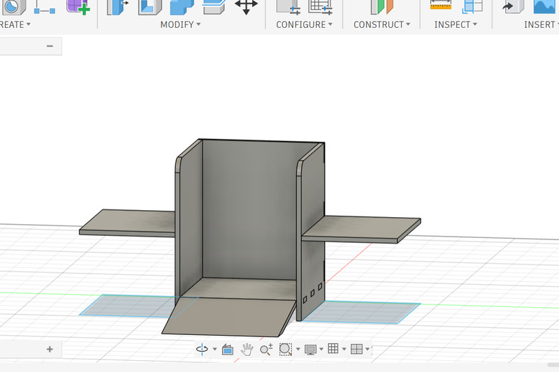
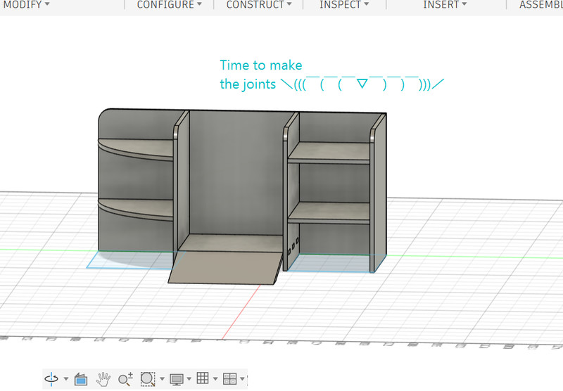
13. After creating the slot and finger joints, I decided to include compartments for my final project components. To do this, I designed two shelves.
14. I followed the same process to create the joints.
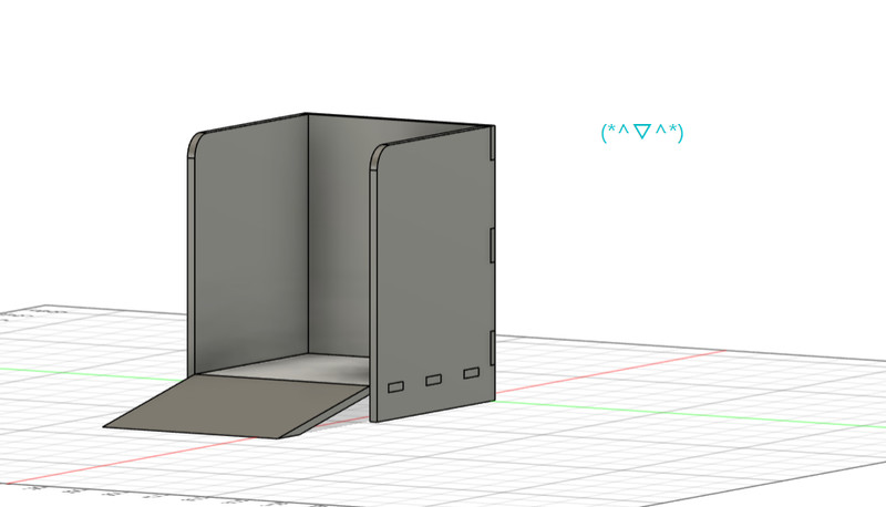
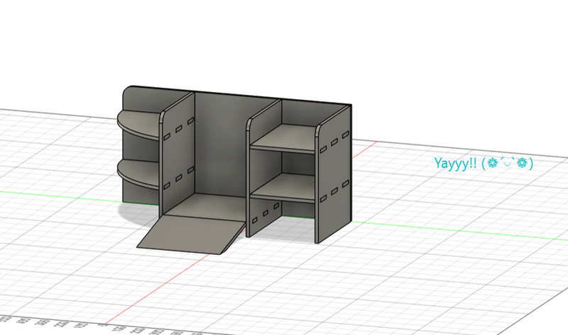
Here is the final look! I'm planning to make the ramp manually after everything else has been cut.
Dogbone
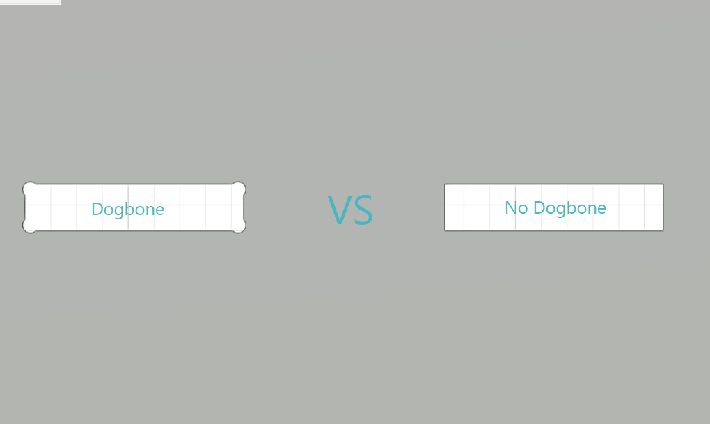
In Autodesk Fusion 360, a dogbone is a small circular cut added to the inside corners of a slot when designing parts for CNC machining. Since CNC machines use round cutting tools called end mills, they cannot create perfectly sharp internal corners. This can cause problems when trying to fit square tabs into slots, such as in press-fit joints. Therefore dogbones are used to provide extra space so that the square parts can fit properly. The shape of this cut resembles a cartoon dog bone 🦴
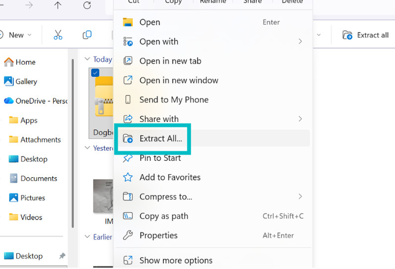
1. I first started by downloading the Dogbone extention as a ZIP file from this link. I then went to my downloads folder and unzipped the file.
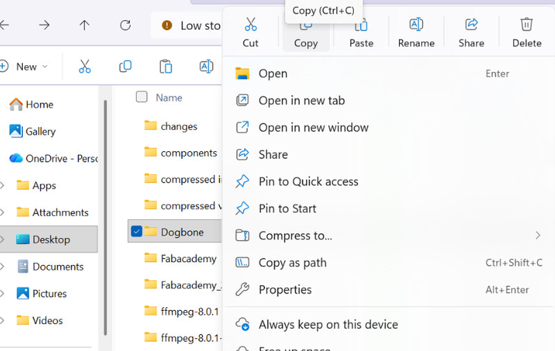
2. I renamed the extracted folder as Dogbone and copied the folder.
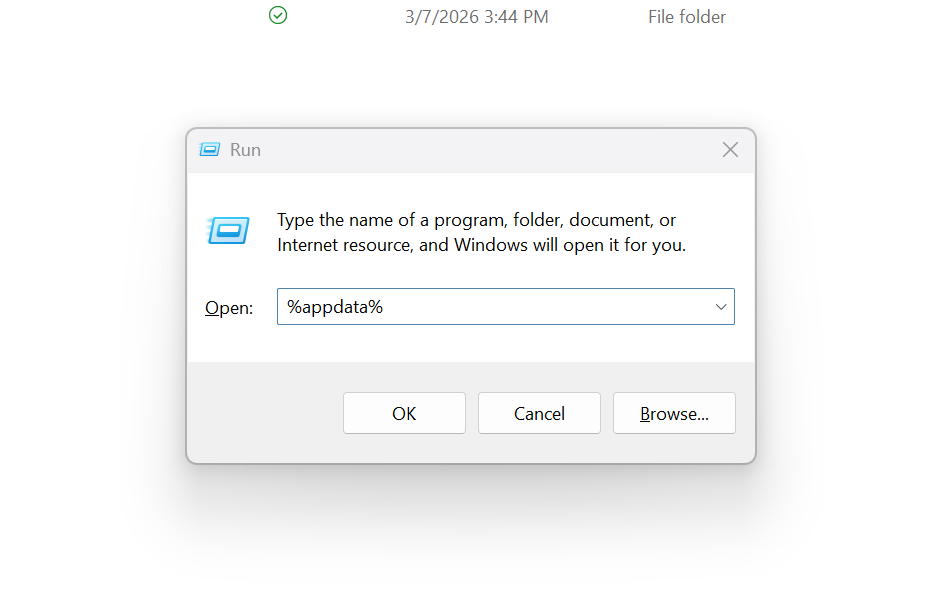
3. I used the shortcut key Win + R to open the Run dialog box. The run dialog box allows you to quickly open programs or folders by typing their name.
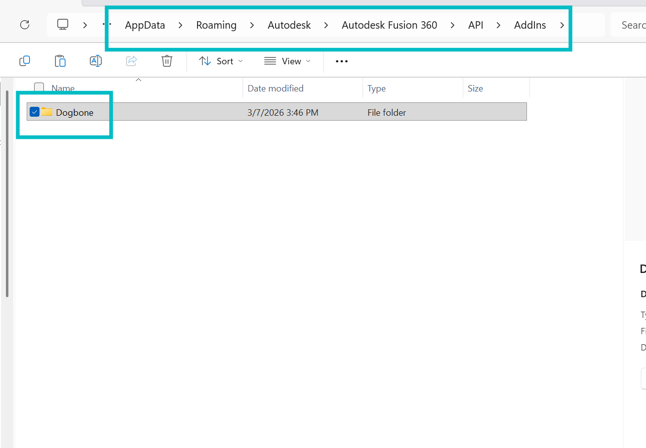
4. I then clicked on Autodesk > Autodesk Fusion 360 > API > AddIns
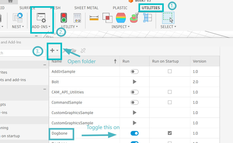
5. After that I opened Fusion 360, clicked on Utilities > ADD-INs. I then opened the dogbone folder and toggled it on.
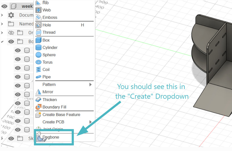
6. In the "Create" dropdown, you should see the dogbone tool.
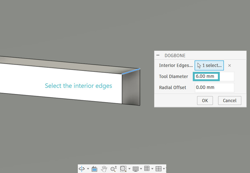
7. I selected the interior edge and used a value of 6mm as the diameter.
8. This is how a dogbone looks.
I did the same for all 39 of my other slots. Note: The boards we had were all between 16-17 mm so I had to go back change my thickness parameter to 16.8mm
VCarve Pro
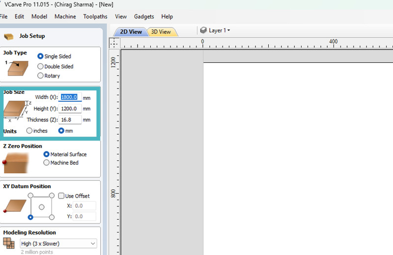
1. First, I set the page dimensions to match the actual dimensions of my board and entered the board thickness.
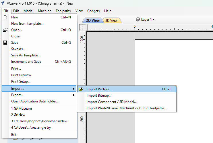
2. I then clicked on File > Import > Import vectors and selected the dxf file.
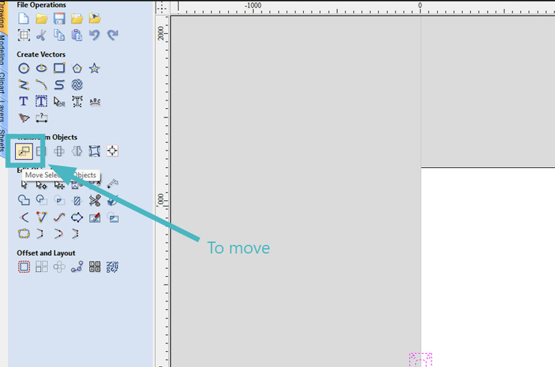
3. To move your design, you can click on this option and do so.
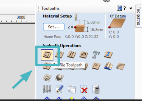
4. After that, I clicked on "Toolpath" which is the highlighted icon.
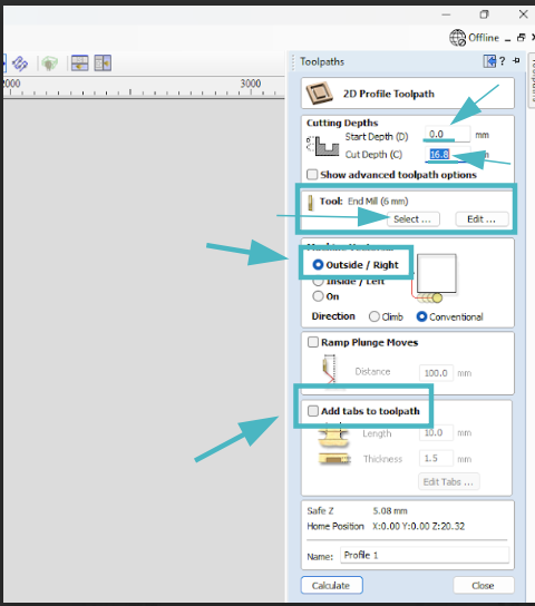
5. I set the start depth to 0, the cut depth to the thickness of the board(If you're not sure about this, you can set it a little higher because there is a sacrificial board underneath), and since we were using a 6mm endmill, I selected that. I also made sure that in "Machine Vectors", "Outside/Right" was selected.
Endmill Selection: Pick an endmill that works well with the material that you are using and the type of design you want to cut. The size of the tool, number of flutes, and coating should also be considered.
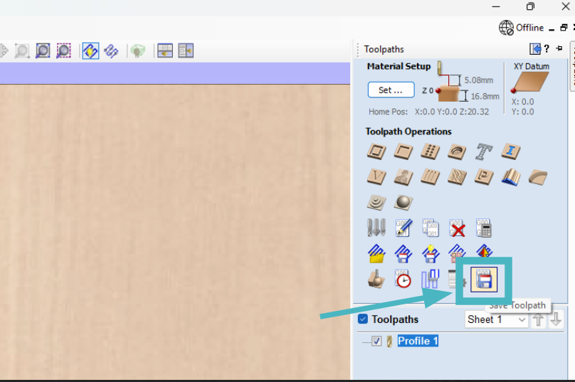
9. Next I clicked on "Save toolpath" and saved it.
10. I then opened Shopbot and imported my toolpath file. This is how my toolpath looks:
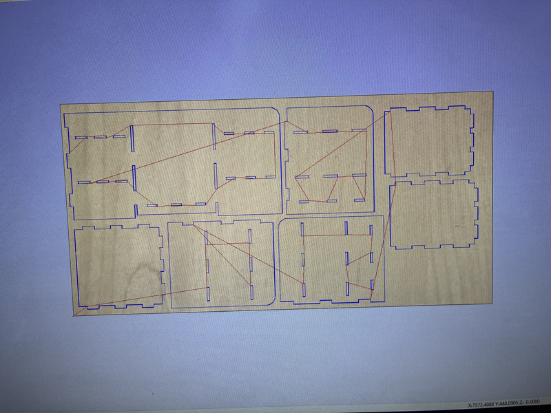
A toolpath is important because it shows where the endmill will move while cutting. This helps you place the clamps in the right position so the tool does not hit them.
Machine Setup
First, I turned on the CNC machine and pressed the reset button. Then I set the X and Y positions to zero.
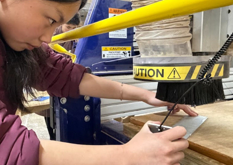
To set the Z position, we used a touch plate.
While setting the Z-axis, the alligator clip from the touch probe must be connected to the endmill. The machine is then moved so the tool is about 5 mm above the touch plate. After that, the probing process is started using the software, which automatically sets the correct Z height.
After finishing this step, it is important to remove the alligator clip from the endmill before starting the cutting process.
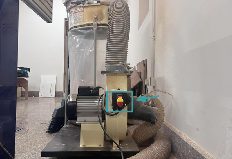
Before starting the cut, make sure to turn on the dust collector by lifting the red lever as shown in the image below.
A dust collector is the system that sucks up dust and wood chips while the CNC is cutting so that the workspace stays clean and the machine works properly.
To start the cutting process, the CNC machine is put on engage, which makes the spindle start spinning. The spinning spindle allows the endmill to cut the material as the machine follows the toolpath. Here is a video of the cutting process.
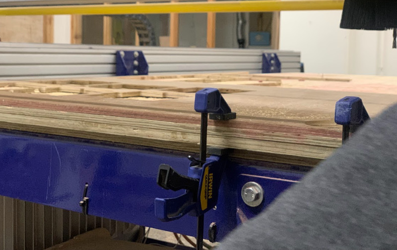
It is important that the board stays steady during the cutting process. Any movement can affect the accuracy of the cut. To prevent this, I used clamps to hold the board tightly to the CNC bed.
Safety Precautions While Using a CNC Machine
A CNC machine is a powerful tool but can be dangerous if proper safety rules are not followed. Here are some saftey precautions that one must take:
- Wear safety glasses to protect your eyes from dust and chips.🤓
- Tie back long hair and avoid loose clothing.
- Secure the material properly before starting the machine.
- Keep your hands away from the cutting tool while the machine is running.
- Turn on the dust collector to remove dust and debris.
- Stay near the machine while it is operating.
- Know where the emergency stop button is.
- Remove tools and clips before starting the cut.
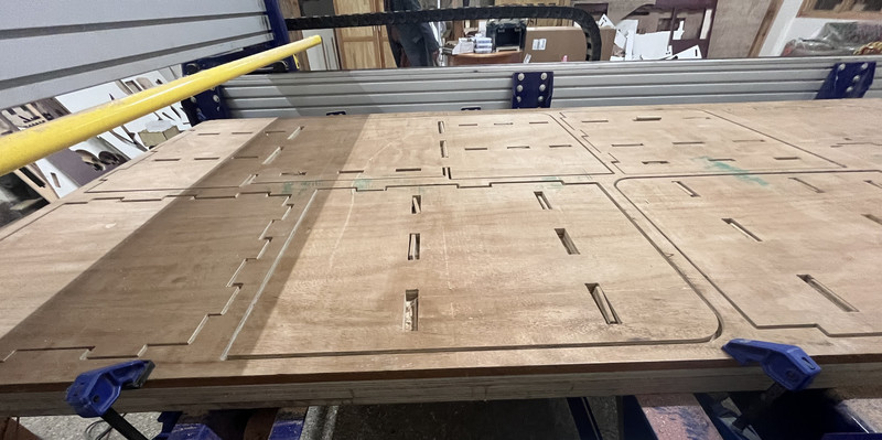
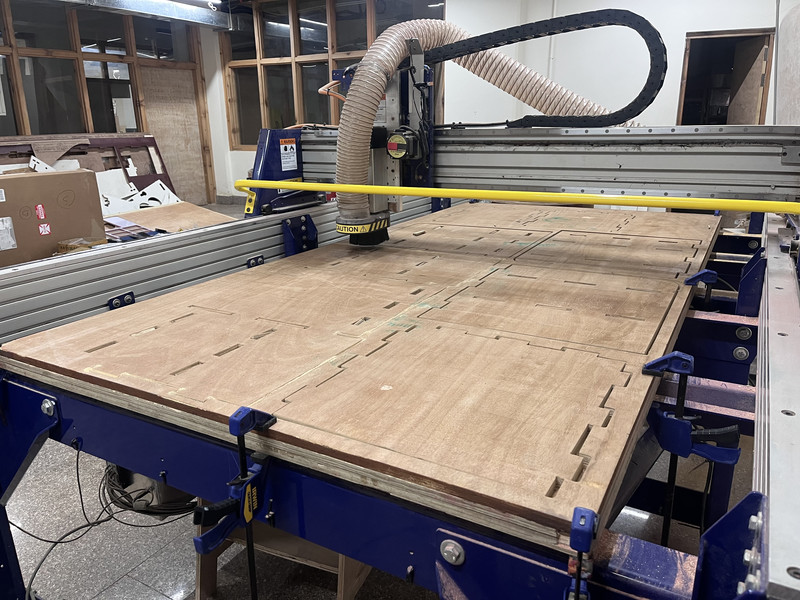
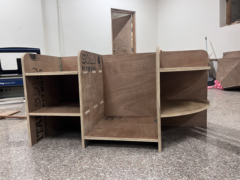
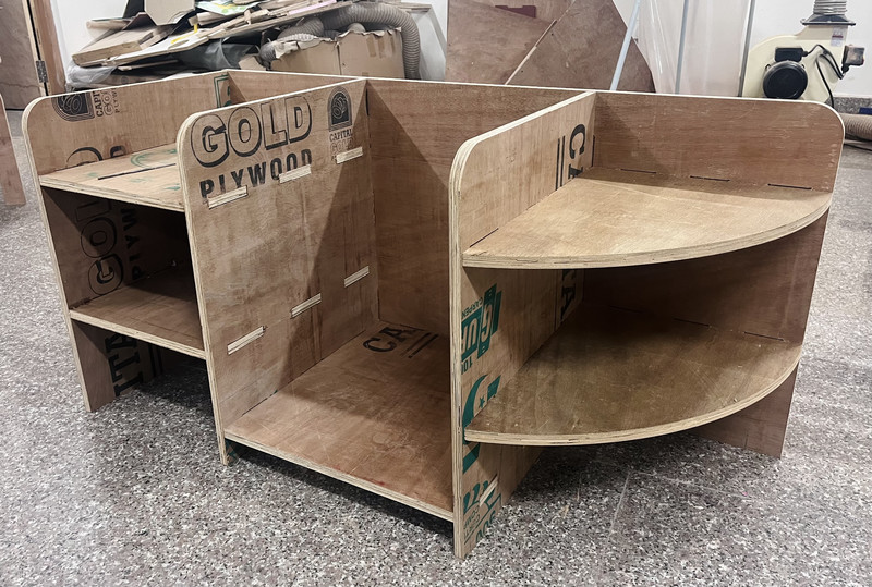
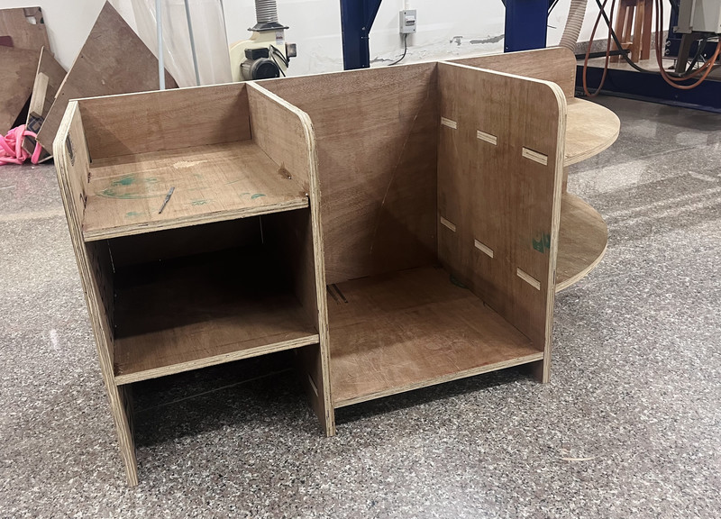
Here are the results:
Here is the final look after assembling!!! 🤠
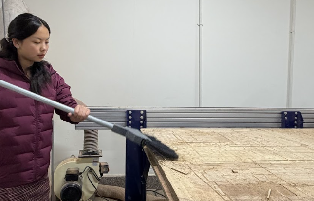
Don't forget to clean afterwards!!!
This week was really fun🪇. Looking back, I realize how much I have improved in designing. Although I referred to Azhim Tsheltrim Lhamo’s website (Thank you Azhim! 🙇♀️) for the dogbone application, I completed the actual design without using any tutorials. It also felt great to apply concepts we learned in class (such as the Pythagorean theorem) to this project. I am really happy with what I was able to accomplish this week, even though I still have the ramp to make 🥲😄