
Week 03: Computer - Controlled Cutting
Assignments:
Group Assignment
- Characterize your lasercutter's focus, power, speed, rate, kerf, joint clearance and types.
- Document your work to the group work page and reflect on your individual page what you learned.
Individual Assignment
- Design, laser cut and document a parametric construction kit (accounting the kerf).
- Cut something on the vinyl cutter
Things to Complete This Week
- Document the group assignment
- Create a parametric design
- Cut a design on the vinyl cutter
- Include original design files
- I also have to make detailed 3-D sketches of my final project
Here is my updated schedule for the week.
.png)
Here is the link to my schedule
Group Assignment
We had our first group assignment this week!!! For documenting our work, we agreed on taking turns and this week was mine. 😉 You can access our group assignment here.
Before any work began, Sir Anith walked us through the laser cutter’s functions and also the mechanisms involved in its operation. As a person who was not very familiar with laser cutting, I was able to pick up a lot today.
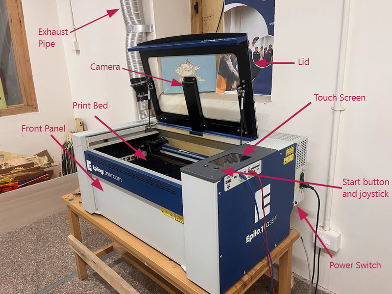
.jpeg)
Here are some of the things that I learnt:
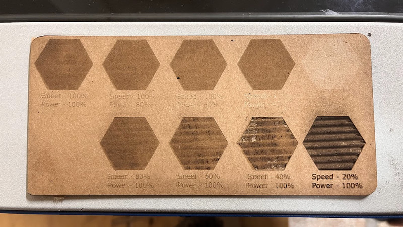
Raster Cut (Engrave)
Engraving is when the laser only burns the top surface of the material to create a design (without cutting all the way through)
- 1. Create or open your design in Inkscape (It can also be any other design tool of your preference).
- 2. Make sure that the part you want to engrave is filled with a solid colour! From this, the laser understands that it has to etch the entire surface of the shape.
- 3. Go to File > Preferences or press ctrl + P to select the laser cutter.
- 4. After that, click Print or Preferences. This should open the laser cutter's dashboard and you should see your design there.
- 5. Assign the engraving settings depending on what you're looking for.
- 6. Place your material on the printing bed. The laser head MUST be at the correct height (depends on the thickness of the material that you're using). To do so, you can use a focus tool and move the laser bed up or down until the tip of the focus tool just barely touches the surface of your material.
- 7. You can then start printing the design!
In our group assignment, we experimented with different power and speed values to see how they affect engraving.
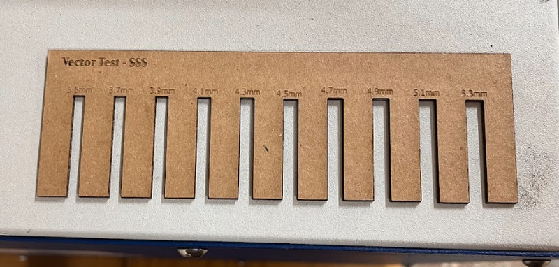
Vector Cut
Vector cutting is when the laser follows a thin line to slice completely through the material.
- 1. Create or open your design in Inkscape (It can also be any other design tool of your preference).
- 2. Set stroke color to a specific color for cutting lines.
- 3. To ensure the laser recognises it as a cut, you can set the stroke width to "Hairline"
- 4. Open in Epilog Dashboard and assign the cutting settings.
- 5. Assign the engraving settings depending on what you're looking for.
- 6. Place your material at the right height.
- 7. You can then start printing the design!
While vector cutting, one very important detail to consider is the kerf. Kerf is the amount of material that is removed when the laser cuts. To achieve accurate and precise cutting results, this must be taken into account. We have calculated the kerf of our laser cutter and more details can be accessed on our group assignment page.
Overall, I feel like the whole process was informative, as well as interesting. It had never occured to me before that laser cutters could be so dangerous, but now that I know the hazards, I will definitely be more careful aorund it. Moreover, I'm so glad that I can now use a laser cutter properly because I have a lot of things in mind that I want to cut. 😁
Individual Assignment
Parametric design is a way to create models where changing a few key values automatically updates the whole design. Such designs are controlled by parameters (specific measurements), so if you change the value of a parameter, the whole design also changes accordingly.
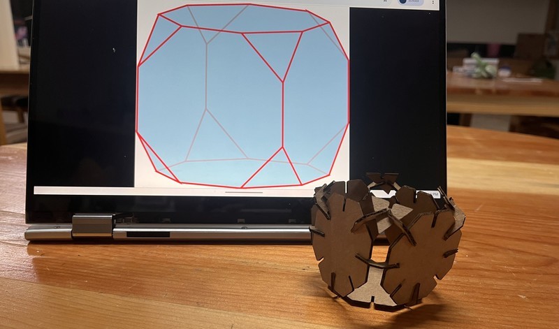
For my main design, I decided to make a truncated cube. Here are the steps that I followed (in Fusion 360):
1. I started by setting parameters. To do that, you can click on Modify > Change Parameters.
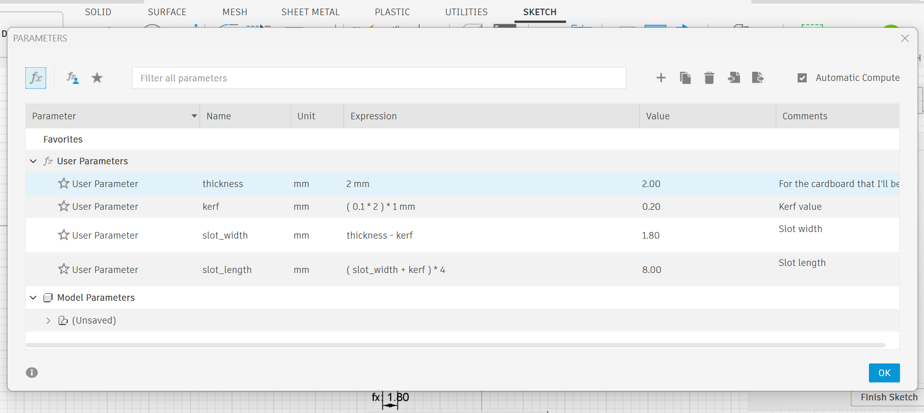
• I set the material thickness to 2mm.
• The kerf on each edge is 0.1mm on each side, so I doubled it to 0.2mm to cover both edges.
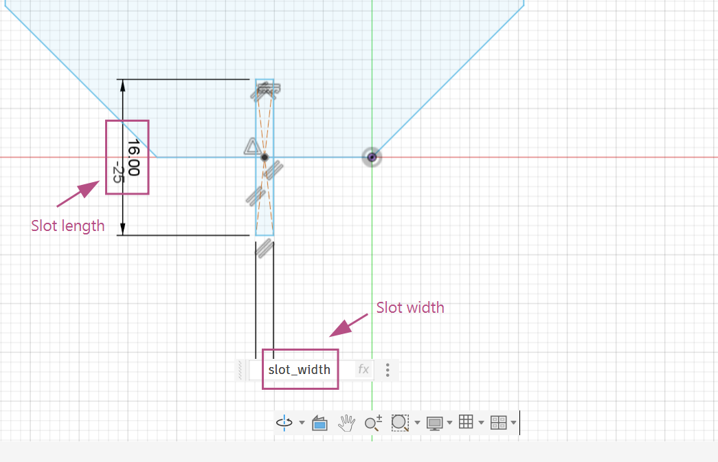
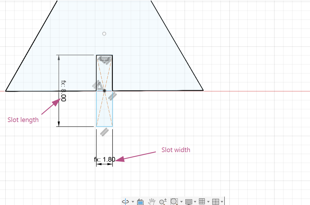
• To make the slot fit well, I set the slot width as material thickness minus the kerf (2mm – 0.2mm), so the slot isn’t too tight after the laser cuts.
• I made slot length longer by adding the kerf and multiplying by 4, so pieces slide in easily without being too loose or tight.
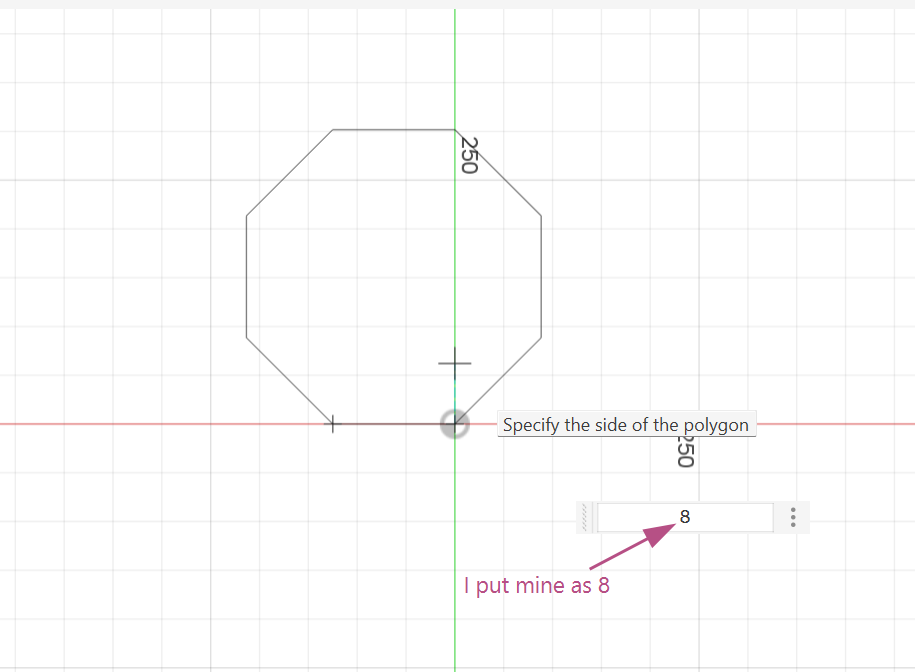
2. First, I created a sketch, then clicked Create > Polygon > Edge Polygon and specified the number of edges.
3. Next, I created a center point rectangle using the parameters that I set earlier.
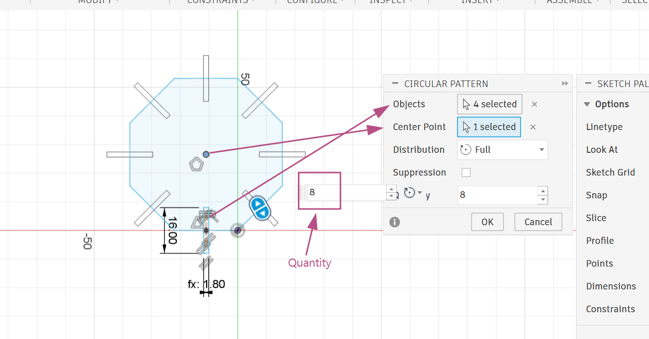
4. I created a circular pattern for the slots. For that, I selected the four edges of the rectangle as the objects and the point in the middle of the polygon as the center point.
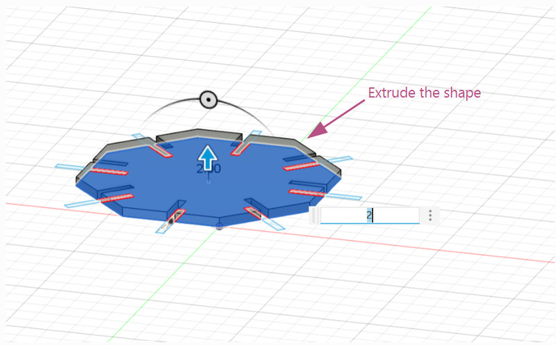
5. I then extruded the shape (Depends on the material that you're using).
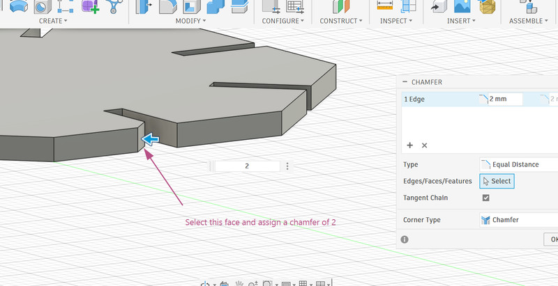
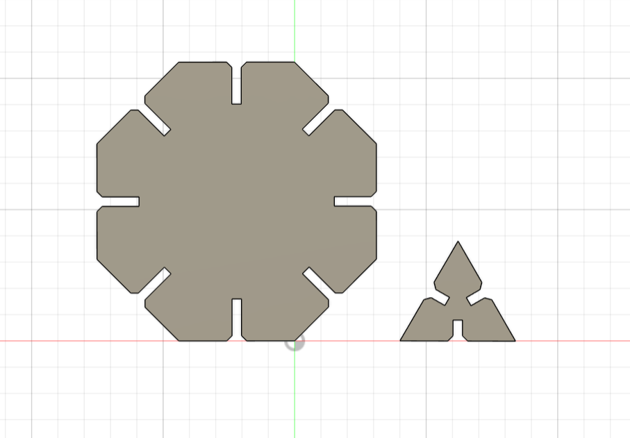
6. To help fits the parts smoothly, I assigned of chamfer of 2mm to the edges of each slot. After doing that, the shape looks like this.
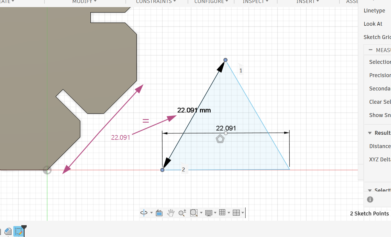
7. Since I want to create a truncated cube, I needed to create a triangle and make its side length match the octagon's side length.
8. I assigned the same parameters for the slots of the triangle and followed the same steps for creating the circular pattern.
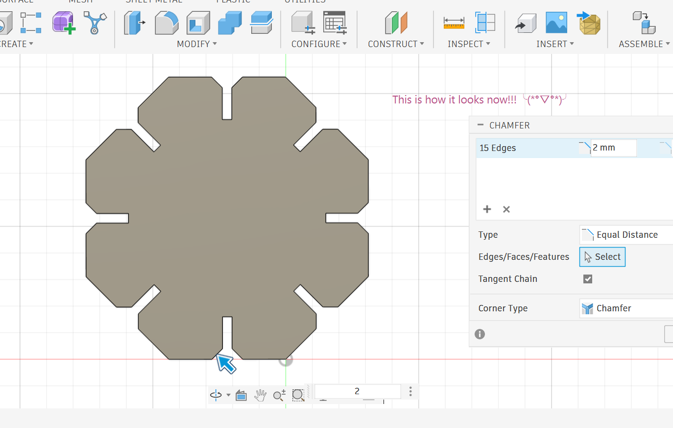
9. After extruding the shape, I realized that a chamfer of 2mm was a little too much so I changed it to 1mm (For both the octagon as well). Here is how it looks now! ƪ(˘⌣˘)ʃ
10. I made a joint using the same parameters. I then extruded the shape.
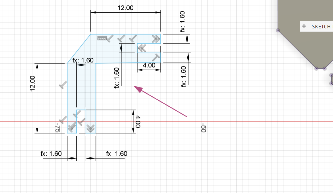
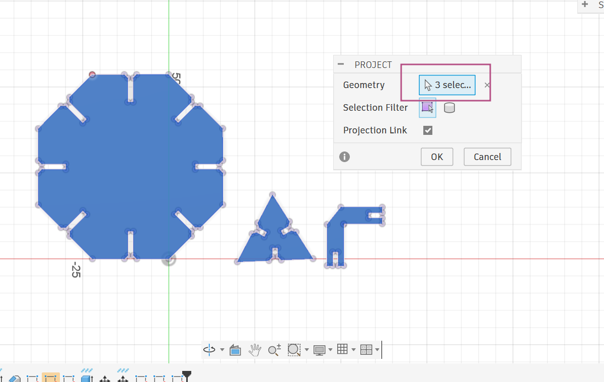
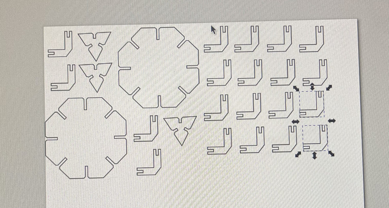
11. Now for the exporting part, I pressed P on my keyboard and a pop up saying Project shows up. I then selected the top faces of all of my shapes and clicked OK.
12. Next I right clicked on the sketch I just made and exported the file by clicking on the Export DXF option.
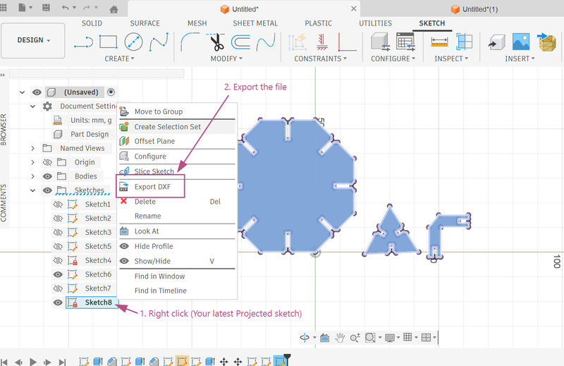
13. I imported my design on Inkscape > Set the stroke style to "Hairline" > Pressed ctrl + P to open the Epilog dashboard > Set the speed to 30% and the power to 50% > I then clicked on the Print option
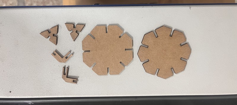
The Assembling Part
Since I had to work with small pieces, I had to be extra careful while assembling the parts together.
Here are the results!!! ☆*: .。. o(≧▽≦)o .。.:*☆
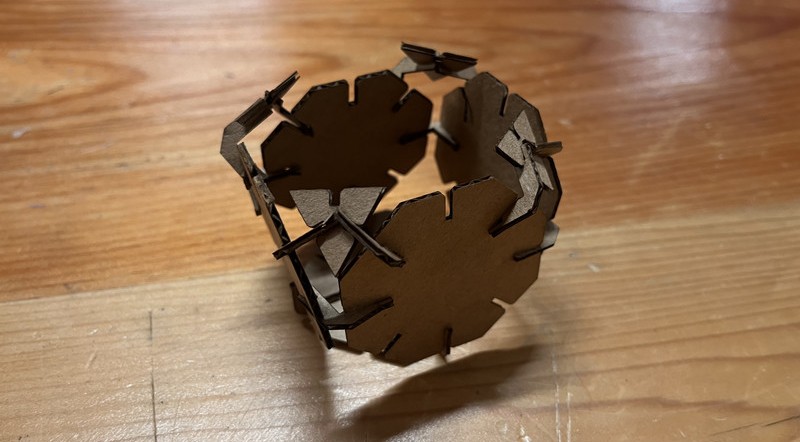
This was my reference. I couldn't make the actual shape because whenever I'd connect one part, the other would fall off (My measurements are to blame for that 😅). I spent a good 40 minutes doing this before I finally decided to create something like this instead.
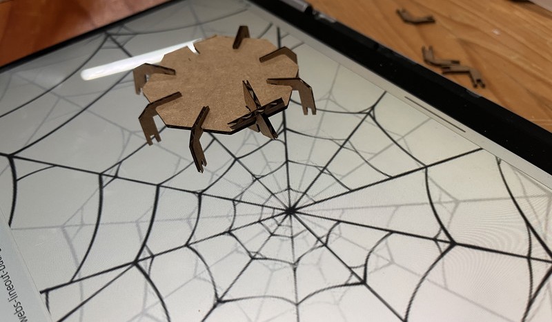
Using the same cutouts, I also created a spider! 😃
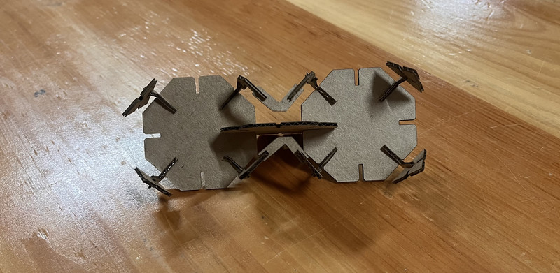
This was just a random design that I created. 😄
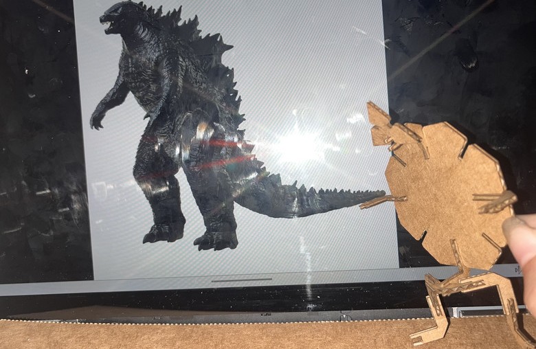
I also ended up creating this design and it reminded me of godzilla. 🫢
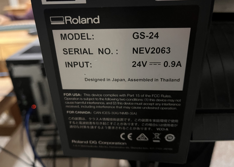
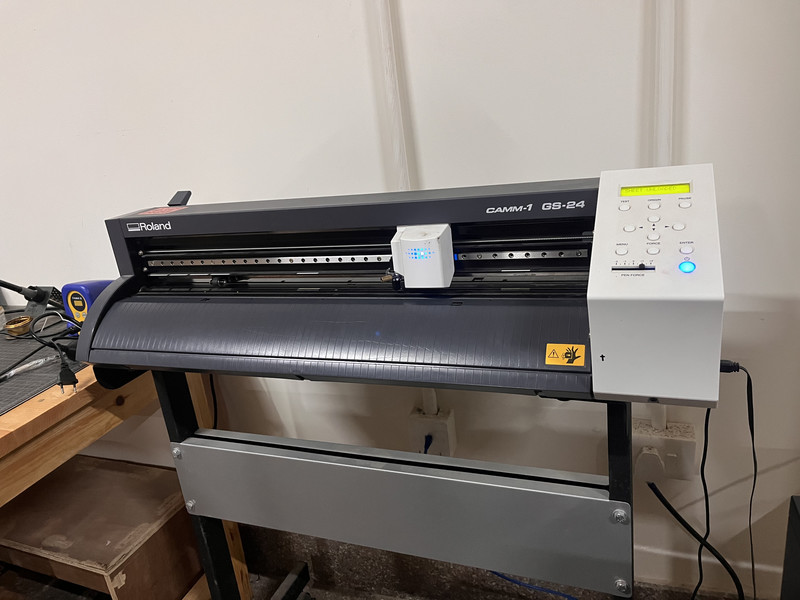
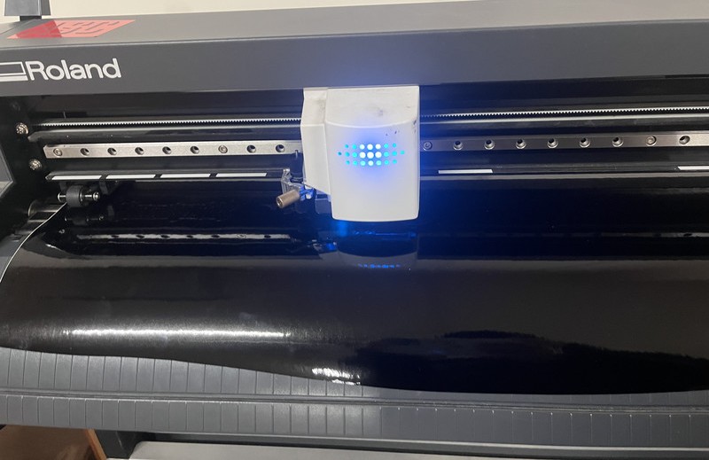
Vinyl Cutter
This is the vinyl cutter that we have in our lab.
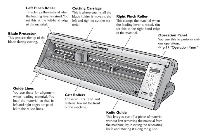
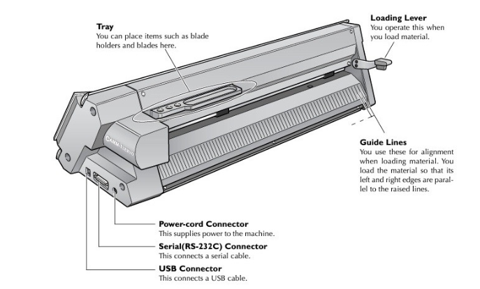
The image below shows the vinyl cutter with its labelled parts and their functions.
Cutting on the vinyl cutter is done using blades of different angles.
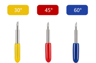
• 30-degree blade - These blades are perfect for dense materials because they are very sharp and fine.
• 45-degree blade - This is the most common blade angle. It works well for most materials like vinyl and paper.
• 60-degree blade - This blade has a steeper angle and is made for thicker or tougher material.
This week, I used the vinyl cutter to make stickers! 😀
1. These are the steps that I followed for setting up the vinyl cutter
- I lifted the top lever to unlock the rollers.
- I then placed the vinyl sheet flat and even against the guide lines.
- After that, I moved the white pinch rollers to press down inside the marked zones.
- To detect the sheet size, I selected the Piece option.
- I closed the top lever to lock the vinyl in place.
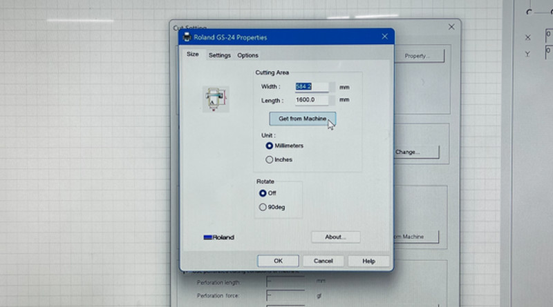
2. I clicked on File > Cutting Setup > Change > Get from Machine to get the exact dimensions of the vinyl sheet on my Cutstudio dashboard.
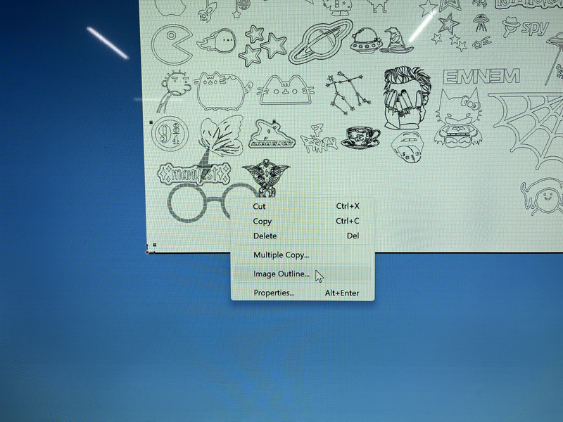
3. In Cutstudio, I started by importing my design and then creating an outline. To create the outline, I right-clicked on the design and selected the Image Outline option.
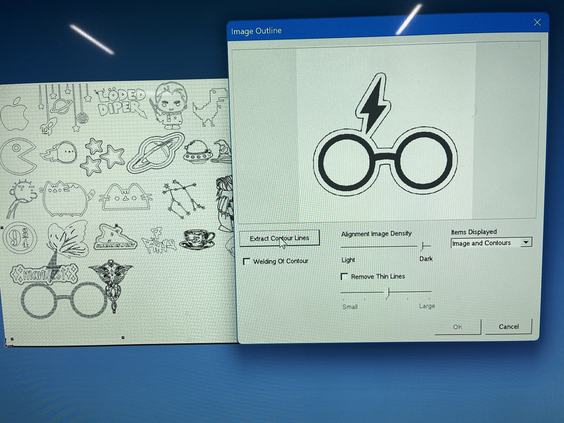
4. After that, I extracted the contour lines.
5. I pressed ctrl + P to cut out the sticker.
I used a 45-degree blade, which works best at a cutting speed of 20 cm/s. The material used was a 3 mm vinyl sheet, and the cutting force was set to 50 gf, as recommended.
Weeding:
After the machine cut the vinyl, I peeled off the extra parts that I didn't need. For this, I used a weeding tool (or tweezers), leaving only my design stuck on the backing sheet.
Transferring:
Once the weeding process was complete, I placed transfer tape on top of it. The tape picks up the design so that you can move it and stick it neatly onto the final surface.
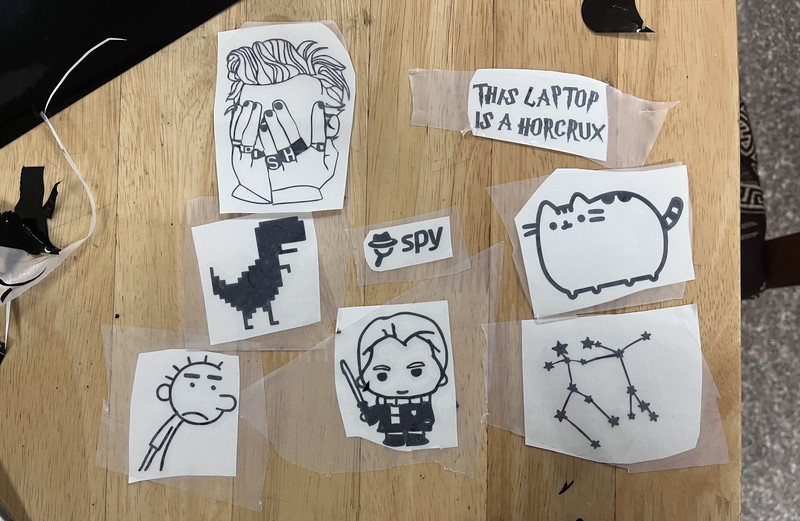
Here are some of the stickers that I cut! ╰(*°▽°*)╯
Note: The images that I used for my stickers came from Pinterest. Thank you to the original artists! 🙂↕️
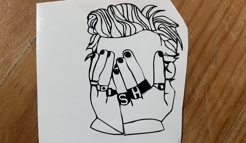
This particular sticker was a nightmare to weed. It was actually my sister who wanted this. (~ ̄▽ ̄)~
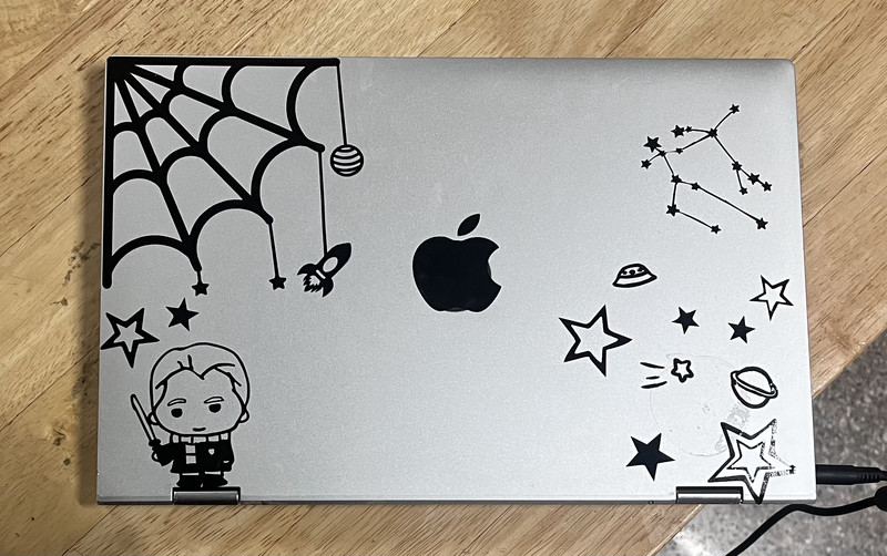
I even customized my laptop. 😄
Here are the download files:
- Download Parametric Design (ZIP)
- Download Engrave test
- Download Vector test
I personally feel like this week was the best one so far. As someone who was not familiar with both the laser cutter and the vinyl cutter, I was able to learn so much in just the span of a few days. I also found the whole process really exciting and had fun throughout. 😃
That is all for this week.