electronics production
Assignment
Group assignment:
- Characterize the design rules for your in-house PCB production process: document the settings for your machine. Document the workflow for sending a PCB to a boardhouse
- submit a design to a board house
- Document your work to the group work page and reflect on your individual page what you learned
Individual assignment:
- Make and test a microcontroller development board that you designed
- extra credit: make it with another process
Added Bonus
Easel Candle Genmitsu
Again, I am hopeful that I will get to learn how to use my little 3018 PROVer machine at home. Especially since the lab is closed and I only got to mill one board before there was a power outage that took another day in the lab from us. Also, my classmate Kim got the same machine, so we are now sharing resources as we learn them.
The Group Work
Link to our group page here
The smaller CNC machines and I work pretty well together. I am gaining a better understand the navigation and see the similarities. I am feeling more confident about my undertanding of what the machine is going to do with each command. I wish I had more experience on these smaller machines before we did the big CNC week. Maybe I would have had a more positive and less stress producing expeiernce.. who knows.. maybe I will go back to the shop bot once I have more carving time on the smaller machines under my belt.
The Individual Work
My asset files are here.
Makera Software/ Carvera Machine
I downloaded the Makera software for our Carvera Desktop CNC machines. They give us a 15 day trial. Then I followed the tutorial from Charlotte Latin School to upload a basic board and to learn to run the Carvera.
We started with Mr. Dubicks Electronics Lesson. This lesson walked us through making a basic board on Carvera from an existing gerber file set.
We imported the gerber files, and then learned to select tools and make toolpaths, finishing with milling the board. There are a preloaded number of tools to choose from in the Makera software in our lab for the Carvera.

When we choose the the tool and the feeds and speeds come up with them. We did chose the cut depth, less than the material for the pocket cut which will remove the copper leaving the trace behind.

The I chose the 0.8 corn tool again to run the outside and the cut out countour path. Notice that the depth is the full amount of the material so that we cut out the board.

When I did the paths for the first time, I didn't have the outer greenline selected and it carved out the opposite of what I wanted. It was goign to mill out all my pads and space instead of leaving me pads and making traces.

Angela suggested that maybe I didnt have my inner green line selected. She was correct. Once I selected the inner green and then recalcalated. The board showed up correctly.

After getting everything set how I wanted it, I ran the tool path preview.

Selected all options for material, tool, path.. Then ran the animation.

I used clamps and the corner screws to hold down the blank.

When I ran my board, the Carvera showed me where the machine would go with the leveling sensor so I could see that it would not hit the fixtures that I was using to hold down the board.

Then after leveling, the board milled.

KiCAD
Did a refresh on some of these tutorials.
Learning KiCAD through these tutorials was helpful.
Solder Mask
Solder mask is a plastic coating on the top of boards that is on top of the copper. Adding a solder masks prevents solder bridges which happens when you're soldering, especially on closely spaced pads, solder wants to flow and connect things it shouldn't. The mask acts as a barrier and keeps solder only where you want it.
Solder Mask Learning from youtube video
Genmitsu Continued...
Using some of the same resources from last week. I continued on my quest to mill ANYTHING on my Genmitsu...
Made a Genmitsu page just dedicated to my Genmitsu to tr to keep some of the learnings together.
Easel
OK - spent ALOT of time today on EASEL. First I had to change all the PNG that I got off a past student site given in class to SVG. I did that in inkscape with the trace bitmap feature.
Then it didn't like my thickness and I had to figure out how to change that in the right window so I could work in the left window with the cut paths.

Claude helped here.. I input the above picture and he gave me some ideas that helped me understand the thickness and where it is set in Easel.
I got my toolpath for the line tester, but then couldn't get the edge cut file not to be huge and run over the inside of the test... need to find a start to finish tutorial doing a PCB on easel.

mods
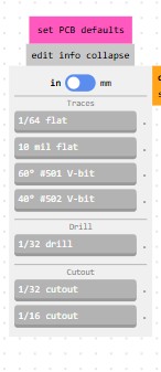
here is a close up of my initial settings

I got the nc file, but knew I needed a GRBL file, but claude let me know that candle would take the NC file just like a GRBL. I brought the code into candle and was pretty excited. I'm out a First Robotics competition right now, but excited about coming back and trying to run this on my machine.
candle

I forgot to save my file in MODS and when I went back in the morning to my restart my computer it was gone. I do have the downloaded nc code and my screen shots so I can remake it if I want. However, I am going to use this as an oppotunity to put in the V bit and try to get a program with that.
I have been having trouble finding initial feeds and speeds for the 3018. So, I took a screen shot of the bit options and asked claude. I have already loaded into cluade all the bits that I have so it can help me. Since they were labeled in chinese and I bought them a year ago, it was really helpful to have claude tell me what they were and I wrote notes in english on stickies on all the packages.
PROMPTS: from these bits which bits do i have & what are the standard feeds and speeds for this bit?
Claude suggested: Here are the recommended settings for a 60° V-bit on the Genmitsu 3018 milling FR1 PCB:
60° V-bit — PCB Trace Setttings
| Setting | Value |
|---|---|
| Spindle Speed | 10,000 – 12,000 RPM |
| Feed Rate | 300 – 500 mm/min |
| Plunge Rate | 100 – 200 mm/min |
| Cut Depth | 0.05 – 0.1mm |
| Step Down | 0.05 – 0.1mm (single pass usually fine) |
Important Notes for V-bits:
Cut depth is critical — because it's a V-shape, the deeper you go the wider the cut gets. For PCB trace isolation you only need to cut through the copper layer which is very thin (~0.035mm), so 0.05–0.1mm is plenty. Going deeper will widen your cuts and potentially eat into your traces.
Start conservative — the 3018 is not the most rigid machine so starting at: - Feed rate: 300 mm/min - Depth: 0.05mm
...and working up from there is safer than starting aggressive.
Leveling matters a lot — because the cut depth is so shallow, any warping in your FR1 board will cause inconsistent cuts. Use double sided tape and press the board down very flat, or use a leveling/surfacing pass first if your software supports it.
Cutout Board Bits
You need to switch bits for the outline cut — do not use the V-bit for that.
Why Not the V-bit: The V-bit is only for shallow trace isolation (0.05-0.1mm deep). Cutting all the way through 1.6mm of FR1 with a V-bit would: - Make a very wide, messy cut - Likely break the bit - Produce terrible results
What to Use Instead: From the bits you have available in Mods, use the 1/32" cutout bit — this is exactly what it's designed for.
The 1/32" is approximately 0.8mm diameter — a straight end mill that can plunge through the full board thickness cleanly.
1/32" Cutout Settings for FR1 on the 3018
| Setting | Value |
|---|---|
| Spindle Speed | 10,000 – 12,000 RPM |
| Feed Rate | 200 – 300 mm/min |
| Plunge Rate | 100 mm/min |
| Cut Depth per Pass | 0.3 – 0.5mm |
| Total Depth | 1.7mm (slightly past 1.6mm board) |
Important Notes for 1/32" Cutout:
- Multiple passes — don't try to cut through in one pass, step down gradually
- Go slow — the 3018 is not super rigid and FR1 is abrasive on small bits
- Tabs — add tabs in your CAM software so the board doesn't shift when the last pass frees it from the stock
More Resources from Open Time
GLOBAL OPEN TIME INSTRUCTORS ON MATTERMOST I decided to go to global open time on mattermost for help and recommendations. The global instructors helped me with some resources for feeds and speeds and the 3018.
Adrián Torres Suggested these:
Here you can find some documentation with the normal end mill https://fabacademy.org/2021/labs/leon/students/mickael-pitarresi/week4.html
And here with the V-bits with the Lunyee https://academany.fabcloud.io/fabacademy/2024/bootcamp-instructors/workshops/Soldermask/
pablo nuñez gave me these:
Marius used Candle as controller software: https://fabacademy.org/2020/labs/fct/students/marius-araujo/assignments/week04/
Super grateful for thier quick responsiveness and help on this week. I am super excited to be getting my 3018 up and running. I have only used it once before to make myself a mirror stand. My struggling eyesight need the mirror closer.

The feeds used in the suggested site are much slower tahn what claude suggetsed, but the bits are different.. I will keep lookeing and test with both.
Ricardo Marques Also gave me some suggestions for another gcode writer and later some advice on my probe and height map.
Using all these notes, I went to mods and made some new code.


The simluation looks so much better.= than when I had a 1/64 bit in there.

Output file called "linetestVbit.nc" Here is what it looks like in notepad... lots of points to go to.

I also needed to make code for the outside line.

These are my settings for the outside cut

Milling using Candle
Now that I have the code, I want to start milling. I am going to use Candle becuase it's what was suggested by Genmitsu and it's what I used before.
Ricardo Marques Also gave me some more resources for Candle.
Setting up the probe
Start with measuring the probe. This You tube will help. I'm using Candle.
Start with measuring the probe itself with a caliper. Make sure the metal piece is above the plastic edges. Or you can find the measurement by bringing the spindle out and let the bit out until it touches the spoiler plate. Then we will taouch reset Zero. this will give a measurement every time the bit is moved. Raise it up 20 mm and then start going by .1 mm and keep going until you can slide the probe underneath. That is another way to get the measurement for the probe.
Mount your material (stock) and get your bit situated how it will be used in your milling and tighten it down. Then put the probe under your bit on top of your material. Clip the red wire to the bit and the probe is connected to the mill board. Leave some room between the probe and the
Probe commands line. If you don't have it set already. (I had it set from before 12.18mm)
G91G21G38.2Z-20F100; G92 Z9.350; G0Z5M30 after G92 where the z where is says 9.350 - change that to be your actual probe measurement Z- 20 lower no more than 20mm at feed rate of 100 until it finds the probe and then raise Z back up by 5mm
Lock XY button in candle and run the Zprobe command .. Magnifyig glass with down arrow.

Remove probe and then use the custom button to move back to your material.
If you make this customer button, it makes it easier to get back to your local zero/the start of your milling code.
Custom Button Code (tells machine to go to x0 y0 and z0):
G90 G0 X0 Y0 G90 G0 Z0
Height Map
It's recommended that you do a heigh map to allow Candle to adapt to the actual variations in the height of the mounted material.
shorter hieght map tutorial that goes with the one above from Jeff Otto
Make a height map to account for uneven surface of the board.
Height map options in the settings below. This is also where you can make your custom position button.

Height Map Making Steps: - Clip on clamp to board and black clip on top of spindle - load code - expand height map option - click edit mode to start editing - sample every 10 mm - divide length each side by 10 and add that into your probe grid settings - zt amount above board when moving between samples. 1mm ok - zb maximum it will go down if it doesnt sense the board = -1.0mm (or -zt) - click probe to start the process - when finished, file, save as - then save to a place that you know and make a note of it. (.map file) - click on edit to take out of edit mode, this should bring your design back up.
When design comes back up, clock on use Height map and load the height map. Make sure the use height map option is selected.

- remove clips and hit send
So I couldn't use the height map becuase I dont have my probe modified so I went for it without the map... LOL
Mill
So I milled without the height map... I had lots of opportunities for learning as I learned more about using my 3018. I am documenting like crazy in the hopes that I will read it later and not have the same issues, and also that it will help me learn from my mistakes and really cement it in my mind.
Bump #1 % < error:1 ... took a screen shot and put it into AI.

CLAUDE
This is the Candle GRBL sender error — % < error:1 means:
The % character at the start or end of your G-code file is not being recognized properly. This happens because:

Some CAM software (like Mods/Fabmodules) wraps G-code with % delimiters at the beginning and end of the file
GRBL doesn't support the % character — it throws error:1 which means unsupported or unrecognized command

The fix is to open your G-code file in a text editor and:

Delete the % on the first line
Delete the % on the last line
Save the file
Re-send in Candle
Done... striped the % from the file by opening in txt and resaving after fix.
Great.. now lets run an air cut by centering z in the air above the part and hitting send.
Bump #2 Spindle not running. I did an aircut and the spindle wasn't starting. So I started trouble shooting that and found out that the top red power connection had come unplugged.

Great... fixed the red power connection. Tested the spindle and it ran. Reload the code. Rezero the machine to the material. Hit send.
Bump #3 Hit limits... so this one was a chance for me to think think think...

It was hitting the limits.. so where? I looked around.. and well.. guess what.. the bit was so high that the spindle could not bring it down far enough to hit the material. The metal spindle holder was as far down in z as it can go.

Great... fixed the bit and put it higher in the collet. Tested the spindle and it ran. Rezero the machine to the material. Reload the code. Hit send.
WE"RE MILLING Woot Woot... so... we're milling but I can see the spindle is too high and not touching the material.
saddertrombones.mp3 by NotR -- freesound.org/s/172950 -- License: Attribution NonCommercial 3.0
I wanted to see what would happen so I let it keep going.

The board milled on one side, but not the other. Some of the traces looked ok. So I have hope or the next one when I get the height map working.

Could be the tape on the back.. and how that impacts if it lays flat.. it was hard to get the tape out. It is a year old or more.. and we really havent used it. i ordered more 2 inch tape. Also, could be that I also used a clamp on that side, so maybe it pushed the material down.
Solution - get the probe modified and do the height map. Instructions from SainSmart of modifying your clamp here. I ordered a second clamp so I can have one regular probe and one modified. I would like to make a splitter eventually so I can have them both connected at once.
I took some pictures of the back so I would know where to reconnect and disconnected the probe.

So I have v2 of the probe so the insides are different and getting it apart was much more challendging and pretty much destroyed the probe. On the bright side, I had purchased a second one so that it was ok to make this one into my height mapping tool.
Me destroying my probe at our kitchen table.

Destroyed but added a clamp and it's working great!

I followed the tutorial.

Checked use the Height Map

Then the heightmap finished and I clicked save. Its such a pretty rainbow.

The program ran all the way through

I milled the line test and it looks great.

I deburred it with an insurance card and it looks even better.
Then I changed the bit, loaded up the linetest ouline file. and selected use the heightmap. The cnc went about one side, and then smapped the bit right off. Not sure why... I will have to work on that. Still happy about the milling of my first PCBish thing on my Genmitsu!

Going to leave it there for now and move on in the interest of time.
Oh ho ho... I forgot to invert my board test.. I will do that later... on the bright note, I have the other board correctly below.
INVERT INVERT INVERT
MODS cuts out the black!!!!!!!!!!!
Making a Second First Board
The plan was to use the board that I milled on the carvera at lab and then brought it home to do my soldering since the lab has been closed for a week now. First we had a power outage and now its spring break. Bu tthen.. on Thursday when I got home to solder, I couldn't find it.. so this sent me a on a long path to mill another on my own Genmitsu. I learned ALOT but also lost 10-12 hours. OUCH!
I loaded the PNG of the board from class into mods and then went through the steps to mill a board. It cut the inverse - i forgot to flip it.. but I hadn't noticed yet and tried to cut it out. Thank you to classmate Kim Alexander for the tests calls and trouble shooting, and the reminder to invert!
I clicked use height map again , but something about that didnt work right after re-zeroing the bit. I couldnt use the same height map. Instead it made holes in the corners but didnt ct through all the way.

Then I ran through mods again. Step by step and milled another correctly. I also enlarged the rectangle in inkscape so that I could use a 1/8 bit to cut out the board becuase that is all I had and the lab is closed.
My mods settings for my v carve bit

My mods settings for doing the cut out.


And my beautiful first circuit board but on my Genmitsu!!!!!!!!!!!!!!!!!!!! The white underneath is the tape that was holding it to the spoil board.

One more picture becuae I am SOOOO proud of what I have done.

Soldering
So I bought some more lights to help with my soldering. Amazon is loving me this week with the lab closed.. wemy teammates and I have become rampant consumers trying to meet the deadlines with what we have at home.

On the advice of Collin Kanofsky I taped the back of my seeed becuase there is copper on the board and external connections on the back of my board. This tape will prevent interference that I don't want.

Then we tested the light to see what color it was by touching both sides while using the connectivity setting on the Multimeter.. and it was red... but I swear it made some other colors too. Stay tuned for that exciting discovery.

I used solder paste to connect the 330 ohnm resistor and a red led to my board, along with the ESP32C3.

Then I soldered on my components with tweezers and soldring iron at 720 degrees.

The resistor fell offduring testing, so I had to go back and solder it on again more carefully.
Testing
Using the multimeter to check for connectivity, I checked my traces. All was beeping.

Then I ran a blinking light program that i got from claude and then modified a bit for longer blinks. (Prompt was something like: write me a program to make a light blink on ESPC3 gpio20 , using it as a pullup pin on high, low to turn off) Turned out to be a multicolor changing light.