Week 7
Check List
This week's project requirements:- Complete your lab's safety training
- Test runout, alignment, fixturing, speeds, feeds, materials and toolpaths for your machine
- Document your work on the group work page
- Reflect on what you learned on your individual page
Individual Assignment:
- Design, mill, and assemble something big
- Document the process
Images/Files:
- Include your original design files
- Properly compress or use a zip folder if needed
- Include hero shots of your results
Extra credit:
- Don't use fasteners or glue
- Include curved surfaces
- Use three-axis toolpaths
Group Assignment:
Resources and Helpful Links
- Aspire
- ShopBot
- Fusion 360
- ShopBot Quick Calculator
- Helpful People:
- Thomas Dubick, Dr Taylor, My Group Partners Camille, Kim, and Dorian
- Thomas Dubick, Dr Taylor, My Group Partners Camille, Kim, and Dorian
Learning Outcomes
- Demonstrate 2D design development for CNC milling production
- Describe workflows and operation for large format CNC machining
Introduction
Creating my puzzle shaped puzzle table was a fun and challenging experience. I have not used a CNC machine before this week. I have been around it since it is in the lab where I work and I had a project earlier this year that was cut on it for me, but I myself haven't personally ran the machine.
Our Labs Safety and Research Material
While looking through the workflow I noticed there were a ton of great links available for additional resources. There is a link to the ShopBot CNC handbook which was filled with valuable information for someone who has never done this before. I skimmed through a lot of the document on my own time, but I really focused on page 16 which was the Safety: A Few Basic Rules page. Also linked in our workflow document was a list of the bits that we have in the auto tool chamber, and I really liked that the document listed the suggested materials for each one. This really helped when I was setting up my tool paths.
Designing my Project
I wasn’t sure what I wanted to make at first, I had made some sketches for some random project ideas like a workshop in a box, a decorative display shelf, and a large storefront decorated doll display. While I do plan to possibly make some of these ideas in the future, I decided I would start a bit similar and do either an end table or bookshelf for my living room. As I looked up pictures of end tables and shelves for some inspiration I got more inspired to make a table as the shelves seemed a lot more plain then I was hoping for.
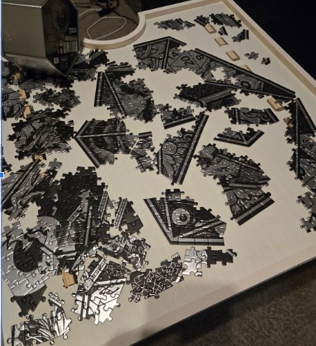
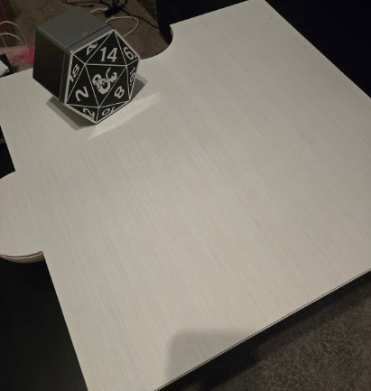
While looking at my apartment I really needed to visualize what the table would look like, where it would fit, and I really wanted something multipurposeful. I have a puzzle I started recently sitting on the living room table and it will live there until it's finished. Taking up the table isn’t ideal, but it's a good surface to work on and the lighting in the living room is really nice for puzzling.
This helped steer me in the direction of making a puzzle table, but of course I wanted something a bit more fun, so a puzzle shaped, puzzle table!
I designed the file using Fusion 360 and I had a handful of iterations before I was happy with my design. As you can see in my Fusion 360 file, I created 37 different pieces, bodies, while I was designing the table.
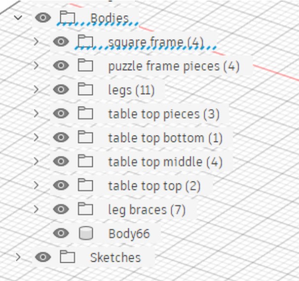
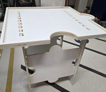
For the table there are two legs, 2 leg braces, the bottom table layer that you puzzle on, a middle rim, and a top piece that sits on the middle rim that covers the puzzle and creates an additional flat surface. The 3 part top allows me to puzzle, store and secure the puzzle, and still have a surface to use as an end table or project space when I'm not puzzling.
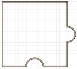
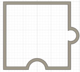
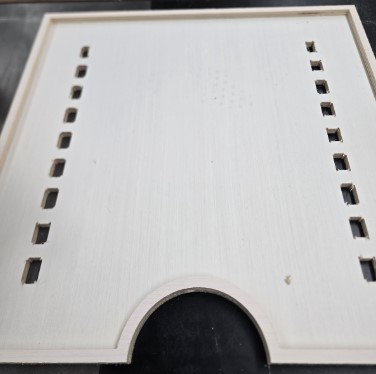
The Puzzle Top
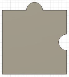
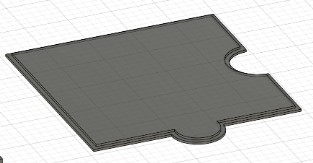
Bottom Piece
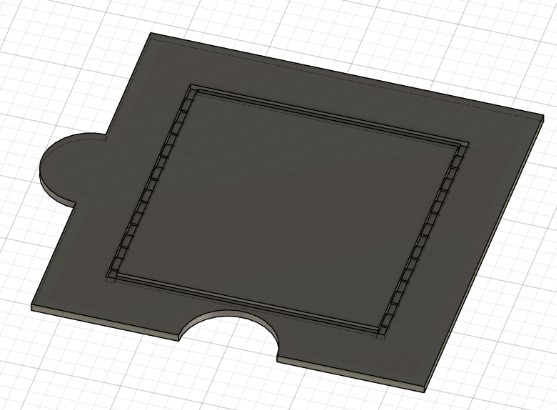
Version 1 (shown): Inset finger joints for leg attachment.
Version 2: The design I cut. I removed the inset channels and cut the finger joints all the way through.
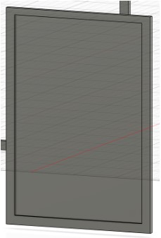
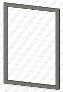
Middle Piece
Version 1: Four interlocking pieces that can easily be removed if an additional table is connected.
Version 2: The design I cut. A solid frame piece.
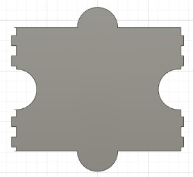
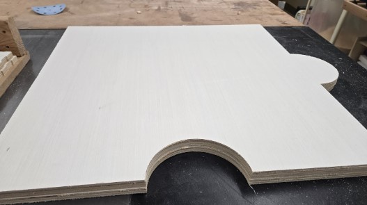
Top Piece
Version 1: A solid puzzle piece shape.
Version 2: A topper piece of a thin edge to allow for sitting on the middle rim.
The Legs
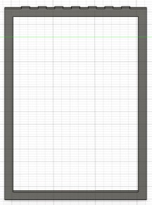
Version 1: A solid frame like design. Meant to slide into the channels on the table top. Could potentially be used as additional puzzle surfaces if disassembled.
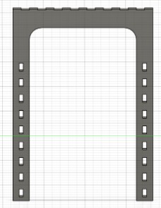
Version 2: An open frame design.
Version 3: Open frame design with finger joint connectors.
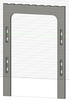
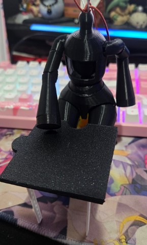
Version 4: U-shaped leg with finger joint connectors and multiple through holes spaced at 1 inch apart to connect leg braces. I 3D printed this version so I could visualize where I like the leg braces.
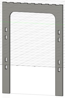
Version 5: U-shaped leg with my chosen through hole locations and channels for the brace to sit in
Version 6: This is the one I cut. U-shaped leg with my chosen through hole locations, but I removed the channels. Not pictured, I adjusted the finger joints to be half inch to match the changes I made to the table top, instead of .125in deep.
The Leg Braces
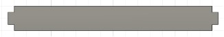
Version 1: A simple straight leg brace
Version 2: The one I cut. A puzzle piece shaped leg brace. Not pictured, I corrected the mismatched finger joint sizes.
Testing my Design before Cutting
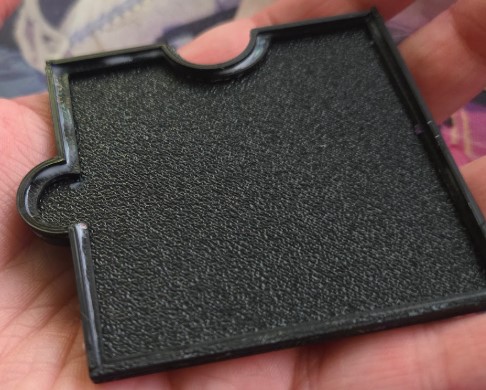
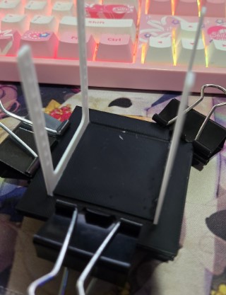
3D Printing
Since my design was made in Fusion 360, I decided to export my finished pieces as .obj files and 3D print them. I scaled the design down to 10% from the original size to quickly print my test pieces in about 30 minutes. This allowed me to visualize where I wanted the leg braces, how everything looked together, and see how the top pieces interacted.
Exporting my Design
To get my 3D model ready for aspire I needed to create a DXF file. I created components from all of the bodies I was using and created a sketch plane the size of my wood. I was suggested to use the arrange feature in the Manufacturing Workspace, but I couldn't actually find the arrange tool, so I went back to the Design Workspace. I used the Arrange tool found in Solids > Modify > Arrange. I selected my shapes and then chose my new sketch plane as my envelope.
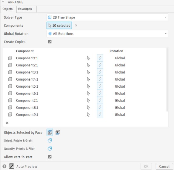
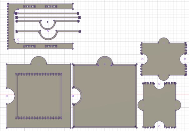
The tool arranged the pieces decently, but it put a bunch of the pieces sideways or upside down. I reoriented the pieces using the Arrange tool and got the pieces arranged how I wanted them. Next I created a new sketch and used the Project tool to create a 2D projection of all of my pieces. From here, I exported my file as a .DXF to bring into Aspire.
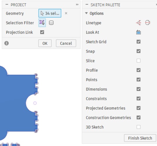
For any files or parts I changed or missed, I was able to quickly right click on the sketch for that part and choose the export as a DXF option. If there were multiple sketch items on that sketch I just deleted what I didn't need when I brought it into Aspire.
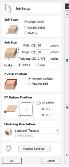
Setting Up my Design in Aspire
I started by creating a new project and setting the job size. I set the width and height to 96 x 48 which was the size of the wood I was provided and I set the thickness to 0.475 which was the average I measured from my 0.5in thick wood.
I brought in my DXF file and rearranged any pieces I wanted to add in or remove, such as removing the four interlocking pieces for the middle top part and bringing in the solid middle piece.
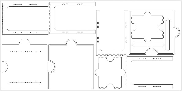
I selected each part individually and used the join tool to create a solid vector. For all my parts that have interconnecting pieces I went into the Fillet menu and added either a dogbone or a T-bone depending on what fit in the small spaces. While I was still in the 2D part of Aspire I also duplicated one of my holes to create a tester hole for fit.
I selected my pocket cut on the table top and set up a Pocket Toolpath using the Drill bit listed below. I then selected all of my outside cuts and set up a Profile Toolpath using the Drill bit listed below. I also created a test cut for my hole using the Profile Toolpath.
Bits used in my project:
Testing the Offset
The first set of cuts I made, after an air cut to test my locations, was one of the straight leg braces and a hole sample. I cut the straight leg brace and the hole using the settings in the Profile Toolpath I set up for my project. This was done to test the fit of my joints. This test was very important because I quickly learned that all of my parts and holes which were designed for 0.5in thick wood (before I had a chance to measure the wood I was given) did not fit well together. There was a lot of wiggle room in the first test.
I was suggested by Mr Dubick to add in an offset to determine the perfect fit for my pieces. I went back to my Toolpath and added in an offset of 0.005. This test still had wiggle room so I cut a new hole at 0.01.
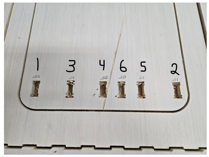
I continued to cut new holes with varying offsets until I found that 0.025 was a perfect fit.
Cutting the Pieces
The pocket cut took about 31minutes and 35 seconds which I was not expecting. This was the longest cut time of any single part in the cutting process.
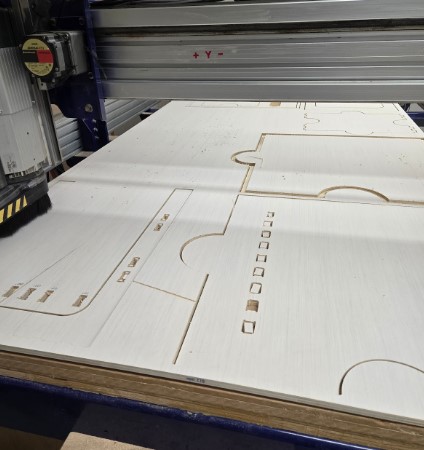
Cutting all of the remaining outside cuts of the remaining pieces took a total cut time of 39minutes and 47seconds. Due to the layout I had set, I decided to cut the two remaining pieces inside the middle puzzle frame and then cut all of the rest of the pieces. I added tabs so I think it would have been fine, but at the time, I was unsure if those pieces would potentially wiggle or move causing an issue with the rest of the cuts.
Finishing and Assembling
Week 7 Files
In my repo is a zip folder containing files for my week 7.
What files are inside my Folder:
My shopbot file for my Pocket Cut
My shopbot file for my Outside Cuts
My Aspire File for my parts
Download My Week 7 Project Files Zip Folder