Embedded Programming
This week we were tasked with an individual set of activities and group work. Working as a group, we needed to review datasheets for different microcontrollers and compare thier toolchains and development workflows. Our group each picked one board from the handful we were given in our lab to do a deep dive. For my group, I worked on finding the data for the ESP32C6. You can view our comparison chart on our Group page.
For our individual activities, we were tasked with browsing through the datasheet for a microcontroller. As stated above, I did my deep dive into the ESP32C6. I used these three sources for the ESP32C6 while working on my group and individual assignments. One interesting fact I learned about the ESP32C6 is that thier is a low powered RISC-V core which is different from the high-performance RISC-V core. After looking into what this means or what benefits this could have, I learned that the low powered core can actually run independently of the high performance core. This can be really useful for my final project because I can have features that work in low power modes!
Week 4
Check List
This week's project requirements:- Demonstrate and compare the toolchains and development workflows for available embedded architectures
- Document your group work on your labs group page and link to your individual page
- Reflect on what you learned on your individual page
Individual Assignment:
- Browse through the data sheet for a microcontroller
- Write and test a program for an embedded system using a microcontroller to interact with local input and/or output devices and communicate with remote wired or wireless connections.
Group Assignment:
Images/Files:
- Properly compress or as a zip folder if needed
- Include hero shots of your results
Extra credit:
Resources and Helpful Links
Learning Outcomes
- Implement programming protocols.
Setting up my Boards and Software
Setting up a Xiao ESP32-C6 in Arduino IDE
The first step to setting up my board was to open the Arduino IDE.
I already had Arduino on my home computer, but I needed to download it on my laptop.
Once I had the IDE installed on my laptop, I needed to add the board specific information to both my laptop and desktop.
I navigated to the Seeed Studio Wiki page for the boards I will be testing with.
About three-quarters down the page, under the Software section, there are instructions on how to update the Board Manager.
After copy and pasting the URL for the .json file, I navigated to File > Settings > Preferences in Arduino IDE.
I pasted the .json file into the Additional Boards Manager section and closed the Preferences tab.
Next I went to Tools > Board > Board Manager and installed the ESP 32 by Espressif.
Setting up MicroPython and an RP2040 Board
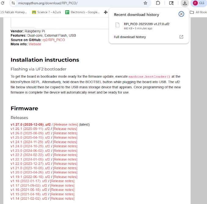
The first step to setting up the RP2040 board was to download the MicroPython firmware.
Specifically, from this page I downloaded the v1.27.0 (2025-12-09) .uf2 file.
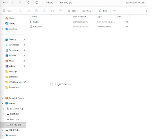
Next I set the board to Boot mode by pressing and holding the B button on the board and then plugging it into the computer. In this mode, the computer sees the board as a normal drive and I was able to drag and drop the .uf2 file onto the board. This configures the board and the board reboots automatically as a microprocessor type.
Setting up VS Code to Program boards
To use VSCode to program boards requires a few initial steps.
The first one is to create a new project folder for the board.
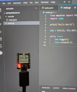
In this case, I created the folder rp2040Projects.
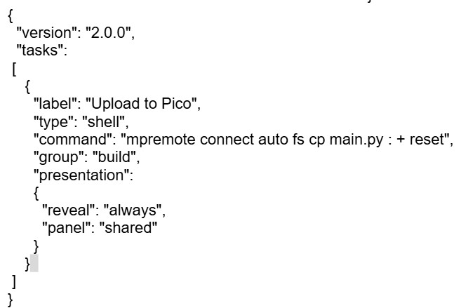
Inside that folder I created a hidden folder called .vscode.
Inside the vscode folder I created and added a file called tasks.json.
I was given the following code by Mr Dubick to add to the task file.
According to Mr Dubick, this code is designed to automate necessary steps such as finding the board no matter what port it is plugged into.
The last step to setting up VS Code for programming the board was to create a main.py file inside the project folder. When testing the automation code, I recieved an error message about the mpremote not being a recognized. I turned to ChatGPT for assistance with the error message. I followed the instructions from ChatGPT and solved one error and recieved a second one which was that mpremote could not find a device. To this error Chat had me check my bash and a few other things to ensure I had everything set up correctly, but this didn't fix the error. Chat gave me a few other suggestions, one of them being the wire as the issue. I tried another wire, and low and behold, it worked perfectly.
Blinking LED's
Blink an LED using VSCode
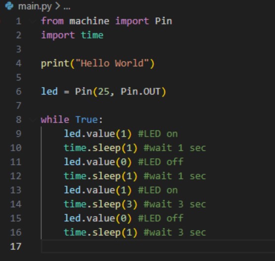
I started with using the provided blink code to test the RP2040 board connection.
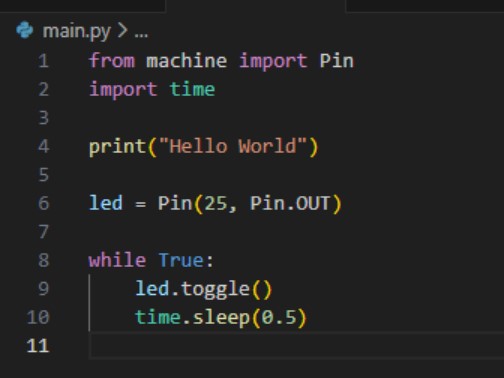
After testing the connection, I modified the given blink code to have a blink pattern.
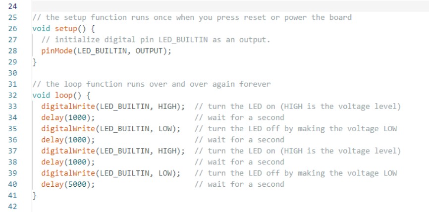
Blink an LED using Arduino IDE
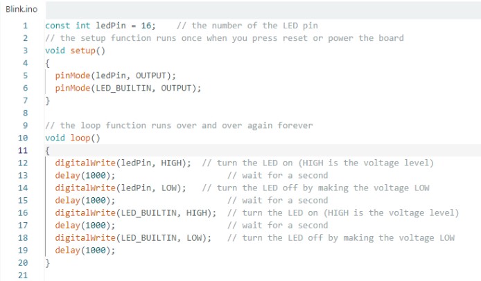
I started with using the example blink code found in the Arduino IDE to test the connection to my ESP32C6.
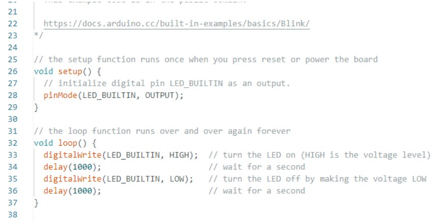
After testing the connection, I modified the given blink code to have a blink pattern.
The Next Step Further Part 1
Trying More advanced Code on my boards
I wanted to try and reuse a code that I had put together last year for an arduino project, but I had a lot of trouble with it on the ESP32.
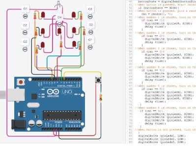
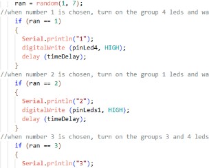
The code from my project from last year, simulates a random dice roll from 1-6 by selecting a random number and lighting up the corresponding combination of LED’s when a button is pressed.
I wanted to try and reuse this program for this week, since I felt it would help me work towards my final project.
I want to have random outputs based on specific inputs, such as a variety of emotives that can be picked from to play on the screen based on a touch sensor being pressed.
Since I had the dice code already figured out with a random generator I thought it would be a good place to start.
I opened up my TinkerCAD version of the project and used that to help me recreate the wiring and code in Wokwi.
However, moving from arduino to the esp32 was not as easy as I expected, and I really needed to backtrack to just a simple led blinking. I used the built in sample led blinking code in Wokwi and modified it to better match my pins.
Reviewing this example, I decided to add an output to the serial monitor on my dice project so I can see if the random number generator is working as expected. Specifically, I added in Serial.printIn("Dice Start") to show as a starting message and I added in the number value as an output for each roll as well.
Now that I had a basic LED blinking and I made some adjustments to my dice code, I needed to figure out why the button was being ignored by the dice code. My dice program was working in the sense that I was getting a random number and the corresponding lights. However it was completely bypassing the button and just continuously picking a number.
I went back to the basics again and added a button to my blinking LED. I struggled with this button working as well. With the help of Chat GPT, I determined that my issue with the button was that I was using the wrong pins. When I rotated the button in Wokwi, I disoriented myself and got my pins on the button mixed up. You can see my example button and LED code here
After solving the pin error and getting the button to respond, I next tried combining the two. I used the basic code that ChatGPT gave me and I tested the button and LED connection. This was finally a successful test of the LED turning on when the button is pressed. You can see my example button and LED code here
Now with a working sample of a button to LED connection, I went back to my initial LED dice program and corrected the button configuration.
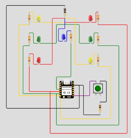
With the button fix, and the code changes, I simulated the program again. Unfortunately, the button was still being bypassed.
I messed with the button state from High to Low, similar to how it was in the simple version, and then everything broke. The LED’s were no longer doing the dice roll and lights which makes me think they are waiting for the button command, but still nothing was responding when the button was pressed. While trying to trouble shoot the issue, I noticed that I missed the int in front of buttonState so I fixed that, but it made no change. With no corrections in sight, I went back to Chat GPT one more time and asked for a suggestion based on what is happening with the button when in the Low versus High state. Chat GPT suggested that instead of using a button state I just try for an event. Based on the explanation of why I should use the event instead, I actually think that would be more beneficial to me in the long run.
How the event options works is that it stores the last button state and then only does the next action when the previous state and current state of the button are in the correct positions. I think for my robot project, that can be beneficial to ensure there are no unexpected overlaps from the triggers and output sounds/animations/ect.
However, after a lot of back and forth with ChatGPT, google searches, and more, I decided to give up on the dice program for now. I was happy with the process of trying to figure it out though, because I did figure out how to orient the button, how to set up a single LED to a button, and how to properly call the pins depending on what IDE I am using.
The Next Step Further Part 2
Building my Physical Button Circuit
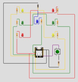
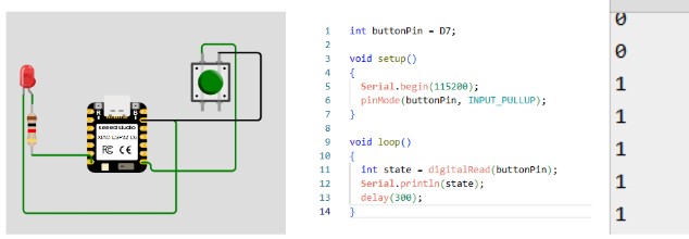
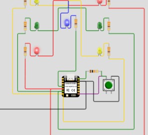
I looked at my working single LED and button simulation and built that on my breadboard.
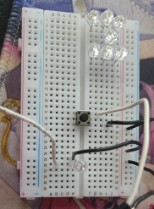
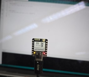
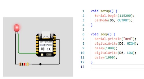
I copied the code into Arduino, uploaded the code, and once again had an issue with the button. I bypassed the button and went back to the basic blink example code in Arduino and ran that code. I made a minor tweak to include both the built in LED and the LED in pin D6. With this code, I had a successfully blinking red LED on my breadboard!
Next, I opened the example button code in arduino IDE and updated my pins to match my button and my LED. Something interesting happened with this setup. My red LED lit up any time the white wire leading out of the button was touched, and also lit up when I gently touched the button but didn’t actually press it. This led me to believe there was a loose wire somewhere along the button wires.
I reached out to my father, an Electrical Engineer, and explained the phenomenon and he said it was due to the static electricity being given off by myself. He suggested I add in a 10k resistor, which I did not have, or use the INPUT_PULLUP command for the button to use what is essentially a built in resistor.
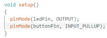
With that simple modification in my code, the button worked exactly as expected.
While I had my dad on the phone, I also asked him about my dice code and wiring. Within minutes of showing him my wiring through a video call, he knew exactly what I was missing, which was moving the resistor from between the button left pin and ground to the top right pin and 5V. You can see my working dice code here
I thanked my dad for helping fix a problem I was struggling with for the past several hours and ended the phone call. Since I had a working button and LED on my breadboard, I decided to test different button sensors in place of the push button. I was able to successfully use a reed switch in place of the button, but I was not able to get a touch sensor to work in place of the button.
This is extremely helpful for my final project since I plan to include magnets for the customization pieces. This shows me that a reed switch could be used to turn some of the cosmetic magnetic connection spots into interactive elements on the desk robot.
The Next Step Further Part 3
Adding the Serial Monitor
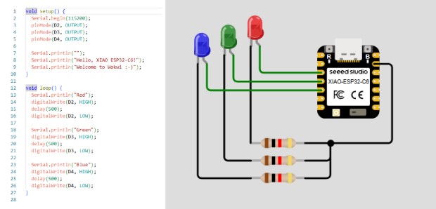
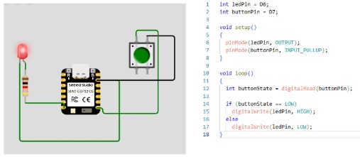
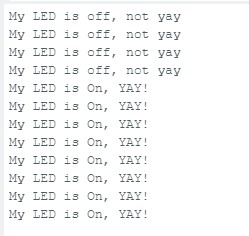
The last thing I need to complete this weeks assingment is to have some sort of communication with the microcontroller along side the input and output. For this portion, I modified my button and LED code to also include a print out on the Serial Monitor. Each time the button is pressed and the LED is turned on, the serial monitor will read out "My LED is on, YAY!." When the button is not pressed, the LED is off, and the serial monitor reads "My LED is off, not yay."
Week 4 Files
In my repo is a zip folder containing files for my week 4.