Computer Controlled Cutting
This week we were tasked with an individual set of activities and group work. Working as a group, we needed to complete our lab's safety training, explore the settings on our laser equipment, and find the Kerf value for the laser and optimal settings. For our individual activities we were tasked with creating something using a vinyl cutter, and creating a parametric construction kit.
Week 3
Check List
This week's project requirements:- Complete your lab's safety training
- Characterize your laser cutter's focus, power, speed, rate, kerf, joint clearance and types
- Document your group work on your labs group page and link to your individual page
- Reflect on what you learned on your individual page
Individual Assignment:
- Cut something on the vinylcutter
- Design a parametric construction kit
- Should be able to assembled in multiple ways
- Accounting for the laser cutter kerf
- Lasercut your parametric construction kit
- Document your parametric construction kit
- Explain how you created the parametric design
Images/Files:
- Include your original design files
- Properly compress or as a zip folder if needed
- Include hero shots of your results
Extra credit:
- Include elements that aren't flat
- Engrave as well as cut
Group Assignment:
Tools, Settings, and Software Explored
- Epilogue Laser Fusion Pro Series
- Focus
- Power
- Speed
- Kerf
- Joint Clearance
Cutter:
- I am using a Silhouette Cameo 4, the current model is up to Silhouette Cameo 5 Alpha
- I am using an origional Silhouette Portrait, the current model is up to Portrait 4
- Silhouette Studio
Parametric Design:
- Fusion 360
Laser:
Learning Outcomes
- Demonstrate and describe parametric 2D modelling processes.
- Identify and explain processes involved in using the laser cutter.
- Develop, evaluate and construct a parametric construction kit.
- Identify and explain processes involved in using the vinyl cutter.
Group Work
My Contribution to the Group Work
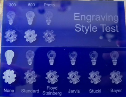
I really enjoyed this weeks group work because I already had a lot of experience and knowledge. I had a lot of opportunities to teach my group mates, some of whome had never used a shilouette machine or a laser before! I helped my group with all aspects of this group work, sharing my knowledge and helping my group mates learn the machines. And, since I already had a lot of experience I wanted to get some extra settings for the laser that wasn't required, but I thought interesting. That is why I designed and engraved the Engraving Style tester. This tester gave me a visual of each of the different dithering patterns that the laser software has built into it.
-
My Contributions to this week:
- Safety Training: I completed my labs Saftey Training as part of the labs onboarding process.
The safety training rules and requirements were reinforced during machine use in the lab environment.
Some important safety rules I followed were:
- Never leave the laser unattended while it is running <-- Most important rule!
- Always double check that settings are correct for the material being used
- Properly focus the laser before cutting - Either manually with the focusing foot or using the automatic Plunger option
- Know where the emergency stop button is in case of an emergency
- Keep the laser area clean and free of clutter to avoid fire hazards
- Ensure the material is safe to cut with a laser and doesn't release toxic fumes when cut - Do not use PVC or vinyl in the laser
- I created this Kerf calculation spreadsheet: Kerf Calculation Spreadsheet The outcome from our Kerf testing was that our Laser has a Laser Kerf of 0.025in and a Line Kerf = Kerf/2: 0.0125in.
- I Taught Camile and Kim how to use the lasers in the lab
- I set up the file in Epilogue laser software to seperate by color so we could test 25 different settings for Power vs Speed in one laser file.
You can see the visual results of that test on the group page.
But our outcome was that the optimal settings for our laser was either 1C or 2E.
- 1C: Power = 10, Speed = 60, Passes = 1
- 2E: Power = 15, Speed = 100, Passes = 1
- I created an acrylic tool to test all of the different dithering patterns
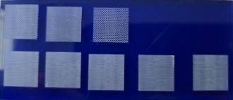
- I created an acrylic tool to test the dpi settings for engraving on our laser
What I learned:
- Kerf must be measured per material and cannot be assumed
- Power vs speed relationships directly affect engraving quality
- Batch testing (multi-setting files) dramatically improves workflow efficiency
- Teaching others reinforces machine understanding more than solo use
Automated Cutting
My Background with Automated Cutting Machines
My experience with automated cutting machines goes back over a decade to the first Cricut machine.
Alongside my mom and sister, I would create scrapbook pages and handmade cards using premade designs on cartridges made for the Cricut.
With the expansive properties of the Cricut Gypsy my mom, sister, and I were able to get more creative by making custom designs and text without the need for specific cartridges.
We then slowly migrated over to the Silhouette brand cutting machines.
Coming from a system of expensive cartridges to the ability to create and cut any design made my creativity soar!
I created elaborate scrapbook layouts and expressive cards to give to family and friends for holidays and birthdays.
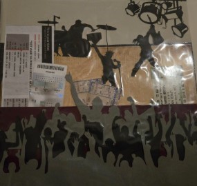
One of my favorite scrapbook page examples was cutting out layers of concert crowd cliparts to create an exciting way to keep and display some of my first concert tickets!
Automated Cutting
Sticker Projects Intro
Over the years I've had the opportunity to work with a variety of different Cutting machines from the first Silhouette and Cricut machines to the current models, and a variety of specialty machines in between.
In more recent years, I've worked with the original Silhouette Curio to do stippling projects and work with thicker materials, the Heidi Swapp Minc Machine to add custom foiling effects to my paper cut projects, the Silhouette Portrait for smaller projects, and the Silhouette Cameo for larger scale paper and vinyl projects.
With years of experience doing decorative vinyl cuttings and paper crafting I wanted to really challenge myself for this week's fab project. I wanted to try creating some new and unique projects, try different techniques, and work with interesting materials on the die cutting machines.
Automated Cutting
Sticker Projects 1 and 2
For this week, I want to showcase two projects I made this year alongside the project I made specifically for this week.
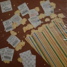
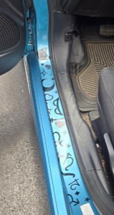
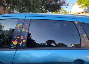
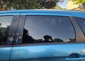
The first project I created over the summer, and it was a set of Sailor Moon themed vinyl stickers to decorate my car.
These were designed in long strips to be applied as one piece.
For this project I used a new material which was a reflective vinyl and I cut these decals using my Silhouette Portrait.
This vinyl gives a very cool effect in different lightings going from a muted gray tone to vibrant colors when the right lighting hits the stickers.
Automated Cutting
Vinyl Sticker Project
The second project I created at the beginning of the school year as a way to try new techniques combining CorelDraw features and vinyl sticker making.
For this project, I used a few of the image editing tools in CorelDraw to create a stylized photo then turned that stylized photo into a vinyl sticker. There was some trial and error in the process of getting the settings correct, but the steps below outline the basic process of creating your own!
- Open your image in CorelDraw
- With your image selected go to Transform > Posterize
- When using Posterize, a setting of 2 should bring your image down to about 4 colors.
Now you will create each color layer - Click on your posterized image and make a copy for each color.
- Starting with the base color, choose all pieces and combine them into a solid. In my example, white was my base color.
- For the next color, remove all previous colors. Based on my example, yellow was my next color. So I removed all of the white pieces and kept the yellow, red, and blue pieces.
- For the next color, remove all previous colors. Based on my example, yellow was my next color. So I removed all of the white pieces and kept the yellow, red, and blue pieces. Combine the remaining pieces to create the layer.
- Continue the process of removing the previous layers colors to create each color layer.
Send to Shilouette - You can bring the file into silhouette in one of two ways.
- If you have a pro account for Silhouette, you can export the CorelDraw file as an svg to bring into silhouette.
- If you do not have a pro account for Silhouette you can bring the file in as an image and trace each layer to create your cut lines.
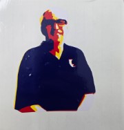
Poster Portrait Sticker Steps
This project works best with images broken down into 4 or fewer colorsAutomated Cutting
This Weeks Project
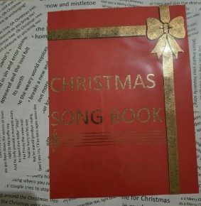
For this week's project, our lab requires us to create a 3 or more color vinyl sticker. This is a tradition for our lab, and each Fab Academy student gets to add their sticker to the window in the lab. Since I have a lot of experience with vinyl cutting, I wanted to try something different than just a basic multi color sticker.
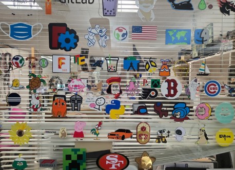
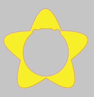
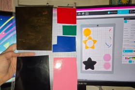
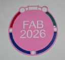
For my sticker I created a star shaped locket, with a center portion that can open to reveal Fab 2026. I designed the file in Silhouette Studio and cut the vinyl using a Silhouette Cameo 4. Below outlines the steps I took to create the sticker design.
-
Design Steps
- Find the Star Locket reference image online.
- Open the Star Locket image in Silhouette Studio.
- Use the trace tool to trace the main features of the Star Locket.
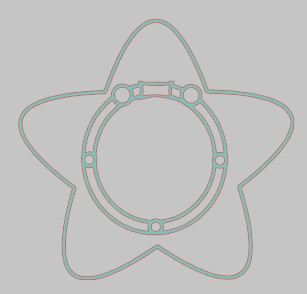
- Click on the Traced locket image and Right Click > Release Compound Path to separate all pieces.
- Create a copy of the traced image.
- On one copy, create the main star piece and the black outline by deleting the inside pieces.
- On the second copy, create the center piece of the locket by deleting the star and outline pieces.
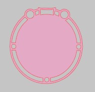
- Make a copy of the center locket piece and use that to cut the center from the star using Modify > Subtract.
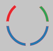
- From the subtraction, take the circle edges to create the red, blue, and green strips. Delete everything else inside the cut out.
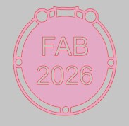
- Use the text tool to create the Fab 2026.
- Use Modify > Subtract to cut the text out of the center circle.
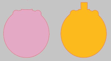
- Create the locket flap by making a copy of the center circle and deleting all of the inside pieces.
- Make two of the flap piece, but add a rectangle to one of the pieces using Modify > Weld
Cut on Silhouette using the correct Vinyl Settings for your vinyl in Shilouette Studio
I initially tried to use the vinyl glossy setting built into Shilouette Studio.These standard vinyl settings didn't cut properly the first time, so I created a test of square cuts with different minor setting changes to find the proper cut settings for my vinyl.- Force = 10
- Speed = 5
- Passes = 1
- Blade Depth = 1
After testing a variety of changes to force and speed, I created a custom Vinyl setting for the material I was using. These new settings were:I think my blade on my portrait may be dull which is why I needed a much deeper blade depth on my portrait than I did when cutting the same vinyl with the Cameo 4.- Force = 10
- Speed = 5
- Passes = 1
- Blade Depth = 5
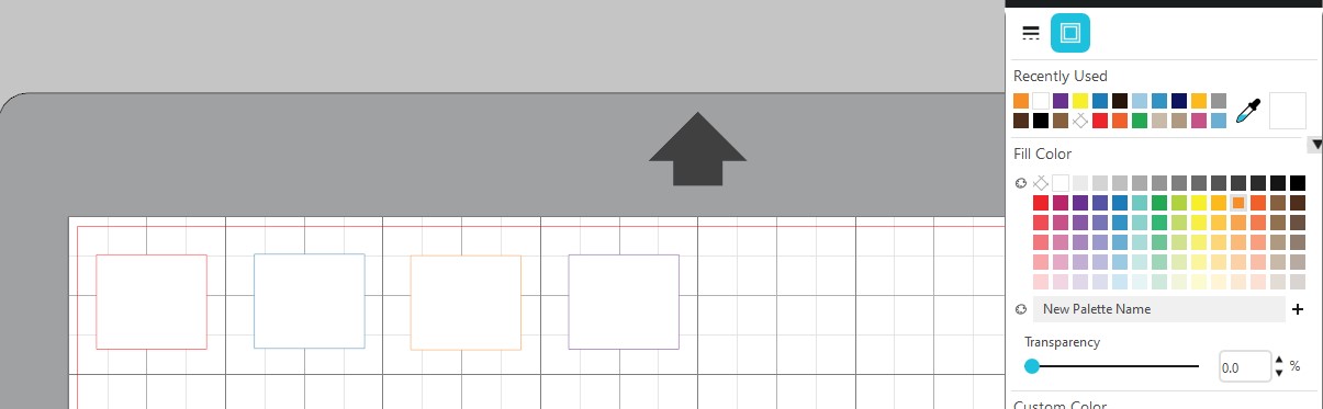
With the correct settings in place, I loaded up my vinyl onto my cutting mat with each color in its own corner or section of the mat. This allows me to cut mutliple pieces in different colors all at once instead of having to do each color individually. With this method, it is important that the mat is loaded with my vinyl in the same way that the screen is set up. Turning on the grid on the screen in Shilouette Studio is helpful for this! Once my vinyl was ready, I lined my mat up with the arrow on the machine and hit the arrow to load it in. Finally I hit the big blue SEND button in Shilouette Studio to begin my cuts.
Sticker Assembly
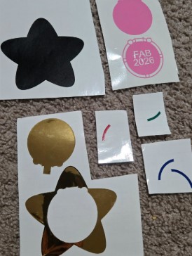
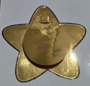
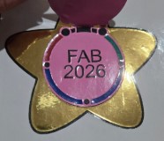
To assemble the sticker, I placed the gold locket on top of the black base.
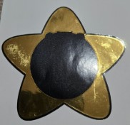
Then I stuck the sticky side of the pink flap to the sticky side of the gold flap, so only the rectangle on the gold flap had usable adhesive. I lined up the flap piece above the yellow star and gently tucked the rectangle piece under the star. I used transfer tape to neatly assemble the inside pieces of the locket.
Finally, I transferred the inside part to the center of the star underneath the flap.
Lasers
Laser Safety and Settings
Our lab has a variety of safety procedures, workflows, and lessons that were shared with us. As a teacher in the lab, I also have an opportunity to remind myself each year of the safety procedures as I teach them to my students. For more detailed information about our Labs safety procedures see our Group Site where the procedures and workflows are available for viewing.
Parametric Construction Kit
Setup in Fusion 360
For this project, I used Fusion 360 to create my parametric construction kit which is engraved and can be assembled in multiple ways.
My construction kit also has a second use, which is being a puzzle when not in use as a building toy.
During the process of creating my kit, I actually designed more than one construction kit.
I started simple with basic shapes like a rectangle, then a square, and then a hexagon.
The goal was to set up my parameter table and test it on the different shapes to see how they all respond.
After finding our laser kerf value in the group assignment, which was 0.025in, I updated the parametric table and tested the square shape again.
To design the shapes and the interlocking tabs in the shapes, I used the following tools in Fusion 360:
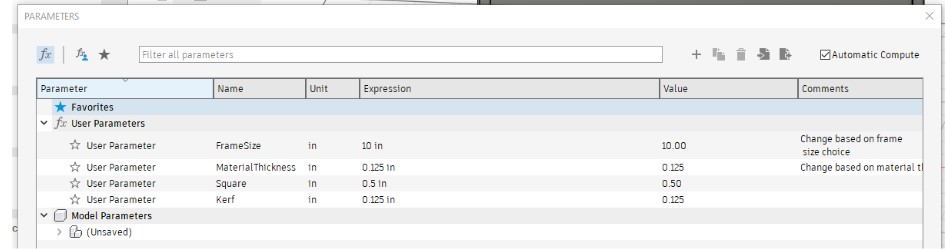
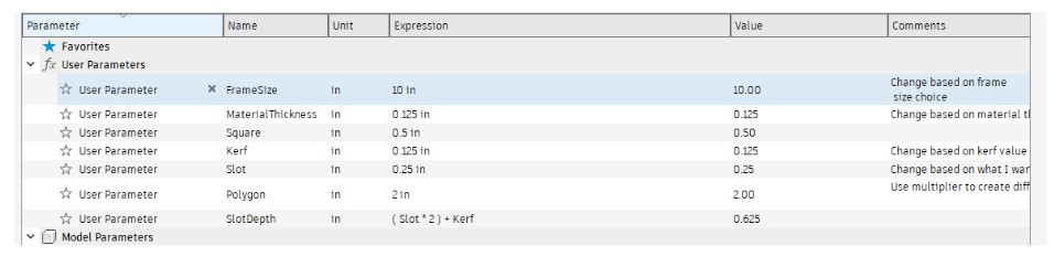
I started with creating my parameter table with the following parameters:
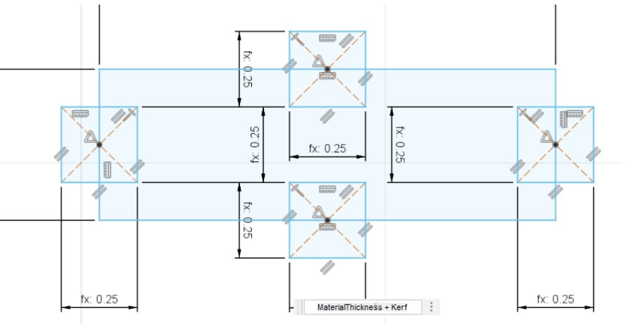
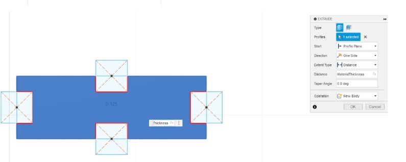
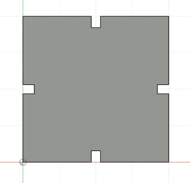
My plan for the shape as I worked with it was to create a sort of puzzle. With that in mind, I created the puzzle board using the FrameSize variable to create the base and extruded it using the MaterialThickness variable. I then created a .25in frame rim around the base that was extruded using the MaterialThicness variable.
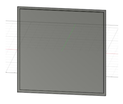
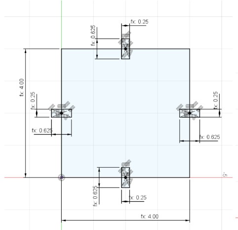
I didn't love the basic shape of the rectangle once it had the tabs cut out, so I played around with the sizes of the tab and the variables. In the end, I decided to change the shape to a square. This was really easy, and quick, to do since I had my parameter table set up. It took about 3 minutes to set up my new square shape which had dimensions Square times 8 or 4in all around. I extruded it using the MaterialThickness variable, and the tabs were created using MaterialThickness + Kerf and (Slot*2) + Kerf.
With how easy and quick it was to create the square, I decided to also go ahead and make a size sided polygon version as well. I used the same variables as the square for the basic shape, but I needed to use move/copy to get the slots at the correct angles around the shape.
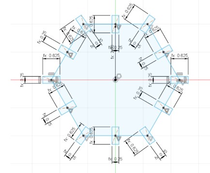
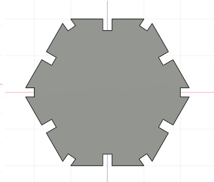
At this point I wanted to play around with the slot depths, and after changing a few by hand, I decided to add SlotDepth as a variable in my parametric table to make future changes quicker.
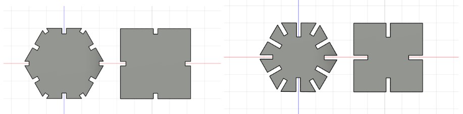
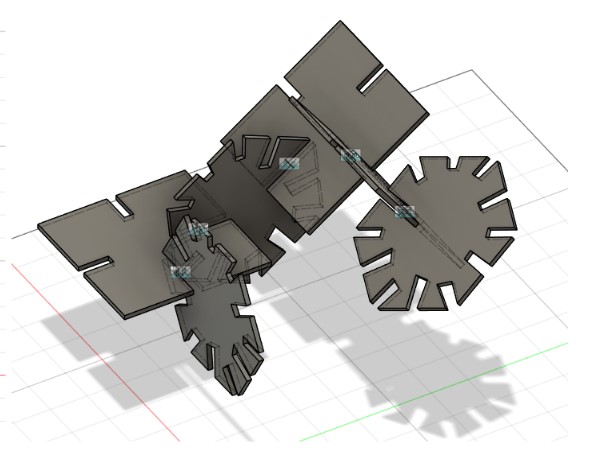
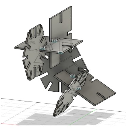
I played with the assembly feature in Fusion 360 to visualize how the slots interacted and used that as a way to make adjustments to my variables.
Parametric Construction Kit
Creating my Puzzle Construction Kit
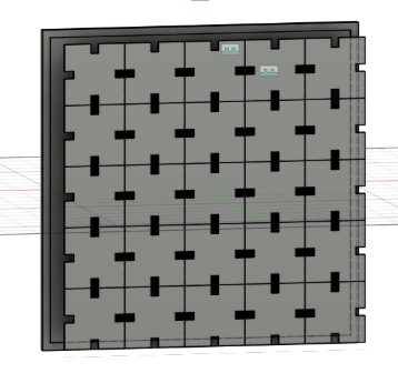
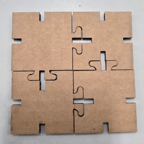
After creating and playing with my basic shapes in the assembly, I started to set up my squares for my puzzle frame.
I went back to my sketch, and I created a 2in by 2in square using the Square parameter times 4.
This size allowed me to fit a 5x5 array of pieces on the frame I designed, which I felt was a great size for a puzzle and enough pieces for building with as well.
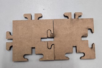
After designing the square puzzle version, I wanted to get a little more creative and make more puzzle like shapes for my puzzle frame. Squares, rectangles, hexagons are all common shapes to find in these types of construction sets, but I hadn't seen a more unique shape like a puzzle piece in these kits.
To help design my puzzle piece, I looked to the art and design world (and math world!) for the design concept of Tesselations. A tessellation is a shape that can be repeated and arranged over and over without gaps or overlaps. This seemed like a viable option for creating my unique shaped construction set. The idea of creating your own tessellation is that whatever shape you add to one side, you remove the same shape from the opposite side. I used this concept to create the pegs and slots for my puzzle piece design.
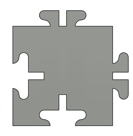
Like all of the other designs before it, I used the MaterialThickness to extrude it, I used the MaterialThickness + Kerf for the width of the slots, and for the depth of the slots I measured the height of the puzzle pegs which was 0.313in. To set up my file for cutting, I used the Project tool to create a linked sketch of my puzzle shape so that I could create a .DXF file of the shape.
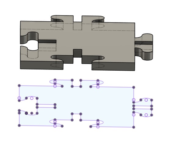
With my .DXF ready, I brought my file into CorelDraw and prepared it for cutting. I converted all lines I wanted cut out to Hairline and then did File > Print which opens up the printer menu. In the printer Menu I clicked Print which opens the file up in Epilogue.
I test cut my first sample on the Epilogue Fusion Pro laser in our lab, and realized I had the old (temporary) Kerf value of 0.125in in my parameter table which was meant to be a placeholder until our group calculated the Kerf value in the group assignment. I fixed the value in the table, updated my design in CorelDraw again, sent it to the Epilogue software, and recut 2 pieces as my sample.
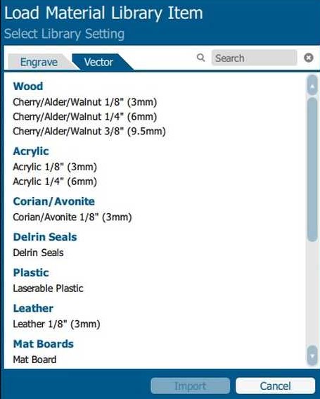
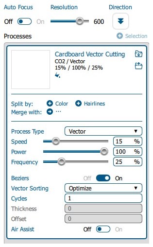
Our lab has a material library set up with settings we use for common materials. The library settings are ones that our lab refined after testing to ensure high quality cuts on each material. We had an issue with our cardboard this year, so we actually have two versions of the cardboard settings depending on how warped or bent the cardboard sheet is. Since the sheet I grabbed was not warped or bent, I was able to use our standard cardboard setting.
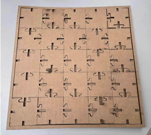
At this point, I looked at my design and decided I wanted to create edge pieces, instead of every piece being exactly the same. For the edge pieces, I simply removed the peg or peg hole against the wall on each piece and added in a simple slot so it could still be assembled on the flat side. I was really happy with my new shapes and the fit of the two sample pieces, so I cut out my 10in base, the frame, and 25 cardboard puzzle pieces.
Parametric Construction Kit
Taking it One Step Further
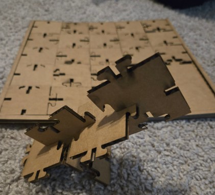
Since my design of the puzzle pieces can be placed in the frame in multiple ways and still build the puzzle, I decided I wanted to also make a pattern that can connect no matter what order the pieces are placed in.
After some research online, I learned about Truchet Tiles which is a tile pattern type first talked about by Sébastien Truchet in 1704.
These tiles are designed to always connect no matter how they are oriented.
This felt like the perfect design style to replicate for my puzzle pieces.
The concept is to keep a consistent location for all points to end/start on the tile.
For my design I planned all locations to end/start in the center of each side of the puzzle pieces.
What happens in the middle of the tiles aren’t as important as those touch points on the edges so I was able to create a different pattern for each tile.
This allows them to be oriented in many ways and create a new geometric pattern every time you rebuild the puzzle.
Week 3 Files
In my repo is a zip folder containing files for my week 3.