Week 16
Check List
This week's project requirements:-
- Design and document the system integration for your final project
- Make a plan for system integration for your final project
- Documented your plan with CAD and/or sketches for system integration
- Implemented methods of packaging
- Designed final project to look like a finished product
- Documented system integration of your final project
- Linked to systems integration documentaiton in your final project page
Images/Files:
- Include your original design files
- Properly compress or use a zip folder if needed
- Include hero shots of your results
Individual Assignment:
Resources and Helpful Links
Learning Outcomes
- Define and apply system integration to your final project
Introduction
My final project combines embedded electronics, interactive sensors, animated displays, laser cutting, pogo style connectors, 3D printing, and physical fabrication to turn a traditional artist style Ball Jointed Doll into an interactive desk companion. This week I focused on making a game plan for finishing my project and planning how all my things will come together to create a functional and emotive friend.
Main Systems in My Final Project
-
- 3D printed body design
- Fully strung and articulated doll parts with standing, sitting, and pose holding capabilities
- Magnetic access panel in the head for easy access to electronics
- Embedded magnets in hand and feet for standing assistance and swappable hand and feet attachments
- Laser cut wooden chair with Pogo style connectors for charging and data transfer
- Embedded magnets in bottom to ensure proper alignment and connection to the chair for charging and data transfer
- Wiring channels and compartments embedded in the head of the doll
Electronics Systems
-
- ESP32-C6 "Brain" board to receive signals from imput sensors and control/manage doll interactivity
- ESP32-S3 Emotion/Screen Controller board (Built into screen module) to display animated facial expressions and control the screen
- Input sensors such as push button and touch sensor to trigger different interactions and emotional responses from the doll
- Pogo power and data transfer system for easy charging and programming access
Software Systems
-
- Processing IDE emotion and face animation design and project simulation
- Animation engine that controls different facial expressions and animations based on inputs from the brain board
- Serial communication between the brain board and the screen controller board to send signals and data back and forth to control the animations and interactivity of the doll
- Custom wakeword and voice recognition to trigger different interactions and emotional responses from the doll based on voice commands and sounds
- UI logic to control the different modes and states of the doll based on inputs and interactions
Communication Systems
-
- Wired board to board communication between the brain board and the screen controller board
- Serial communication between the brain board and a computer for programming and debugging
- Serial communication between the brain board and a computer to listen for voice commands/wakeup word
User Interaction Systems
-
- Touch interaction using a touch sensor on the top of the doll head to simulate petting the doll and trigger a unique face animation and interaction
- Custom wakeword to wake up the doll and trigger a unique face animation and interaction
- Emotional feedback system to provide emotional responses and interactions based on the different inputs and interactions with the doll
- Charging animation that triggers when the doll is connected to the chair to provide visual confirmaiton of successful connection and charging
- Push button interaction on left and right side of head to trigger different face animations and interactions depdning on how and when the buttons are pressed
Physical Systems
Physical Systems
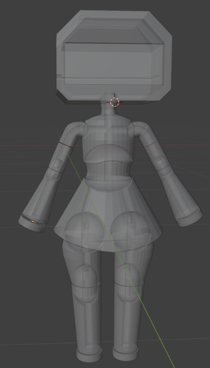
3D Printed Ball Jointed Body Design
The body is designed based off of traditional ball jointed dolls. This design allows for a wide range of motion and poseability, as well as the ability to stand and sit unassisted.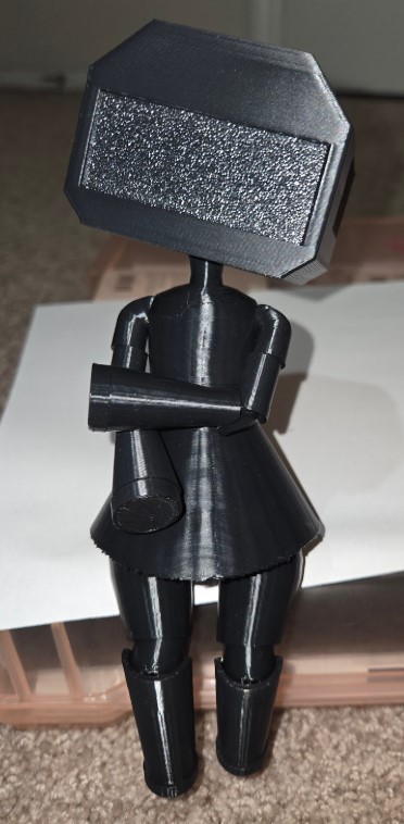
Their is an internal channel system designed into the body pieces to allow for elastic string to be threaded through the body. The elastic string holds the joints together, provides tension on the parts, and allows for pose holding. Their are also internal compartments designed into the head of the doll to hold the electronics and wiring in place.

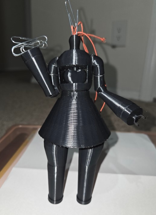
Their are magnets embedded into the hands and feet of the doll to allow for swappable attachments. Their is a hinge and a magnet set into the front and back of the head of the doll that allows for easy access to the electronics, charging ports, and stringing system. Their are magnets set into the bottom of the doll to align the doll with the chair for charging and data transfer.
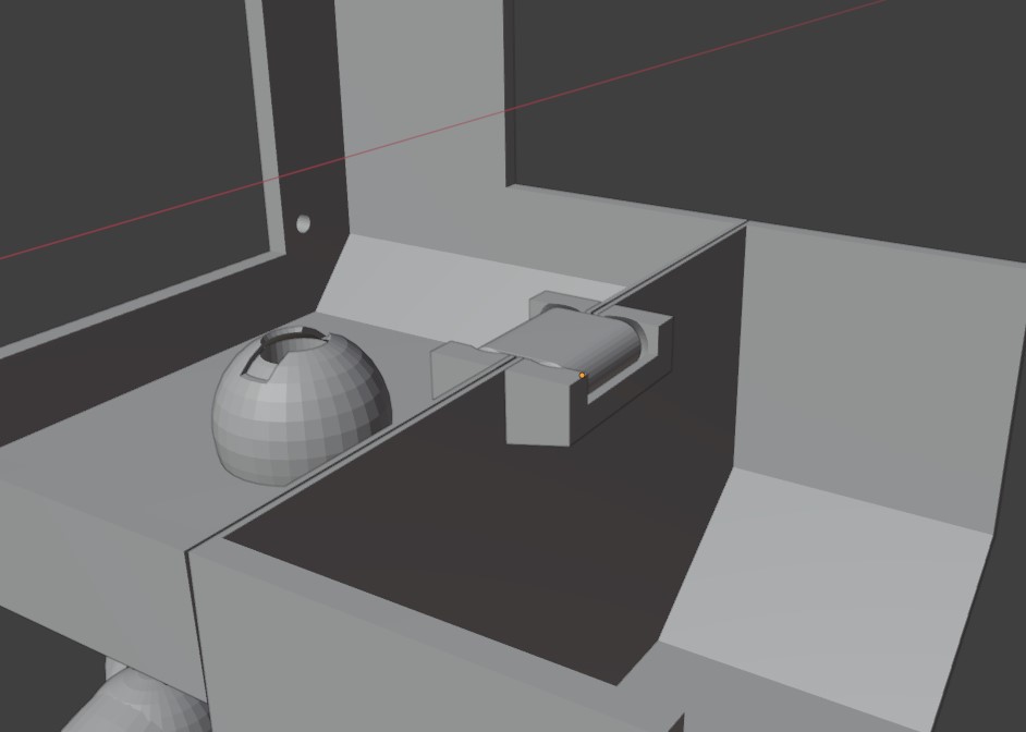

Finally, thier is a laser cut wooden chair that astecially hides the charging wires and charging system.

Electronics Systems
This is my KiCAD schematic for my "Brain" Board which controls the input and output sensors and tells the screenboard what emotions or animations to display.

This is my KiCAD schematic for my Sensor Boards. Each sensor is built onto its own breakout board which can be plugged into the screw terminals on the Brain board. This system allows for future additions to the project or to easily test out, or change, to different sensors and inputs.

Software Systems
Processing Simulation Example of the emotions and interactions I hope to implement into to my final project.
This is a test of my custom wakeword and voice recognition system that I plan to implement into my final project. The video shows the system recognizing the wakeword "Hi Triss." Normal static or noise sits around 0.6, but when the wakeword is spoken the score drops to between 0.2 and 0.3.