2. Computer Aided Design
This week I worked on designing the 3D model of the robotic arm lamp using both Fusion 360 and Onshape, exploring parametric CAD modeling and assembly workflows.
Assignment checklist
- Modeled an object in 2D and 3D using CAD software
- Used parametric design in Fusion 360 and Onshape
- Documented the CAD modeling and assembly workflow
- Included design files
- Included hero shot(s) of the model
Evaluate and Select 2D Software
Before starting my design work, I compared two popular 2D vector design tools to determine the best fit for this project.
| Feature | Adobe Illustrator | Affinity Designer |
|---|---|---|
| Pricing | Subscription (Adobe Creative Cloud) — school license available | Free (acquired by Canva in 2024, now free for all users) |
| Industry Standard | Yes — widely used in professional environments | Growing adoption, but less prevalent |
| Ecosystem Integration | Seamless with Photoshop, InDesign, Adobe suite | Integrates within Affinity suite only |
| File Format Support | AI, SVG, EPS, PDF, DXF, and more | SVG, PDF, EPS, AI (limited), Affinity native |
| Learning Resources | Extensive tutorials, community, and official support | Good documentation, smaller community |
| Performance | Resource-intensive on older hardware | Lightweight and fast |
| Advanced Features | Variable fonts, generative AI tools, live trace, scripting | Non-destructive editing, pixel-perfect design mode |
My Choice: Adobe Illustrator
I chose Adobe Illustrator because the school provides a license at no personal cost, so it is fully accessible. It is the industry standard, with strong file-format support (especially SVG and DXF for laser cutting and fabrication), a large community, and smooth integration with the rest of the Adobe suite. Although Affinity Designer is now free after its acquisition by Canva, Illustrator’s broader ecosystem and fabrication-ready export options make it the better fit for this course.
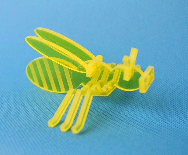
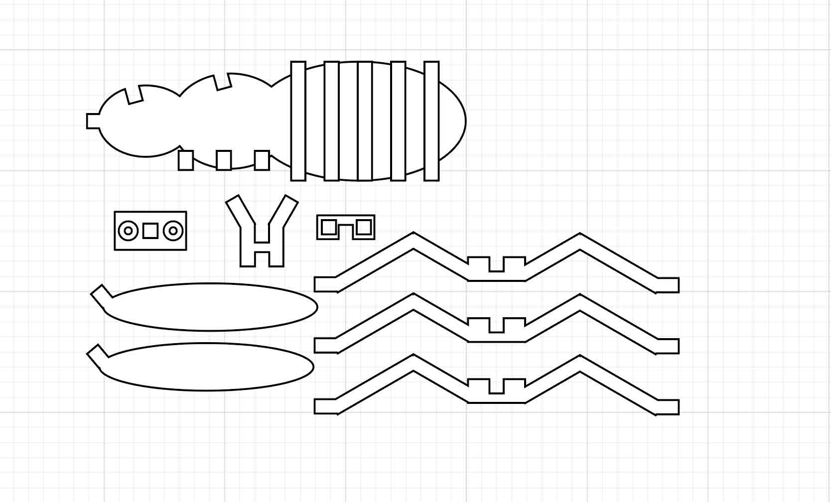
I used Illustrator to draw the 2D vector artwork for laser cutting: flat parts that assemble into a three-dimensional Bumblebee-style model(大黄蜂的立体模型).
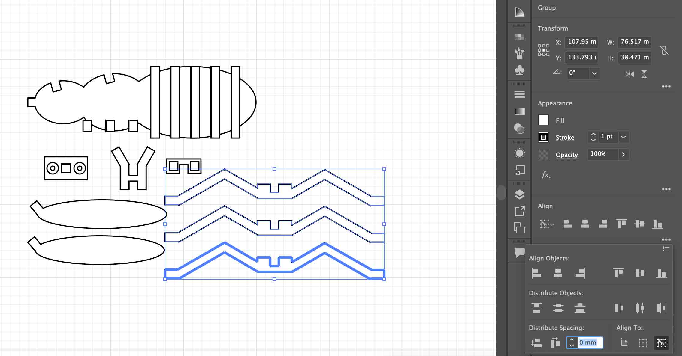
I also practiced aligning and spacing multiple objects to exact distances. In the Align panel, choose Align to Key Object, select the key object, then use Distribute Spacing (horizontal or vertical) to set the gap between that object and the others.
Evaluate and Select 3D Software
I also compared several 3D design tools to find the right fit for parametric modeling and fabrication tasks in this course.
| Feature | Onshape | Fusion 360 | Blender | Rhino |
|---|---|---|---|---|
| Pricing | Free (education/public), paid plans | Free for personal use, paid for commercial | Free and open-source | One-time license (~$995) |
| Platform | Browser-based (cloud), no install needed | Desktop (Windows/Mac), cloud sync | Desktop (cross-platform) | Desktop (Windows/Mac) |
| Modeling Type | Parametric CAD | Parametric CAD + CAM | Polygon / sculpt / procedural | NURBS surface modeling |
| Collaboration | Real-time multi-user collaboration | Cloud-based sharing | File-based, no native cloud collab | File-based |
| CAM / Fabrication | Basic export (STEP, STL, DXF) | Built-in CAM for CNC and 3D printing | STL/OBJ export, no native CAM | Export to STEP, STL; plugins for CAM |
| Learning Curve | Moderate — intuitive browser UI | Moderate — feature-rich interface | Steep — complex for engineering use | Steep — NURBS workflow differs from CAD |
| Best For | Team-based mechanical design | Integrated design-to-fabrication workflow | Visual/artistic 3D, animation, rendering | Architecture, complex surfaces, jewelry |
I selected both Onshape and Fusion 360 as my primary 3D tools. Onshape is ideal for collaborative parametric modeling with no installation required — perfect for working across devices. Fusion 360 complements it with its built-in CAM capabilities, making it well-suited for preparing models for CNC machining and 3D printing directly within the design workflow.
Demonstrate Image and Video Compression
For web documentation, keeping file sizes small is essential for fast page loading and staying within GitLab repository limits. Below are the workflows I used to compress images and videos.
Image Compression — Photoshop Export for Web
I used Adobe Photoshop's Export As Web feature to compress images before adding them to the site. Here are the steps:
- Open the image in Adobe Photoshop.
- Go to File → Export → Export As… (or use the legacy File → Export → Save for Web (Legacy)… for more fine-grained control).
- In the Export As dialog, set the Format to
JPEGfor photos orPNGfor images with transparency. - For JPEG, drag the Quality slider down — a value between 60–80% is a good balance between quality and file size.
- Resize the image under Image Size — for documentation purposes, a width of 1200px or less is usually sufficient.
- Check the estimated file size shown in the bottom-left corner of the preview. Aim for under 100 KB per image.
- Click Export All and save the compressed file to your images folder.
Video Compression — HandBrake
I recommend HandBrake for video compression — it is free, open-source, and available on Windows, Mac, and Linux. It can significantly reduce video file sizes while maintaining good visual quality.
- Download and open HandBrake.
- Click Open Source and select your video file.
- Under Presets, choose Web → Vimeo YouTube HQ 1080p30 (or 720p if smaller size is preferred).
- Set the Format to
MP4and the Video Codec toH.264. - Under the Video tab, set Constant Quality (RF) — use RF 22–26 for a good size/quality balance (higher RF = smaller file but lower quality).
- Set the Framerate to 30 fps (or match your source).
- Under the Dimensions tab, set the resolution to 1280×720 or 1920×1080 as needed.
- Click Browse to set the output destination, then click Start Encode.
- Once done, verify the output file size — for documentation videos, aim for under 50 MB.
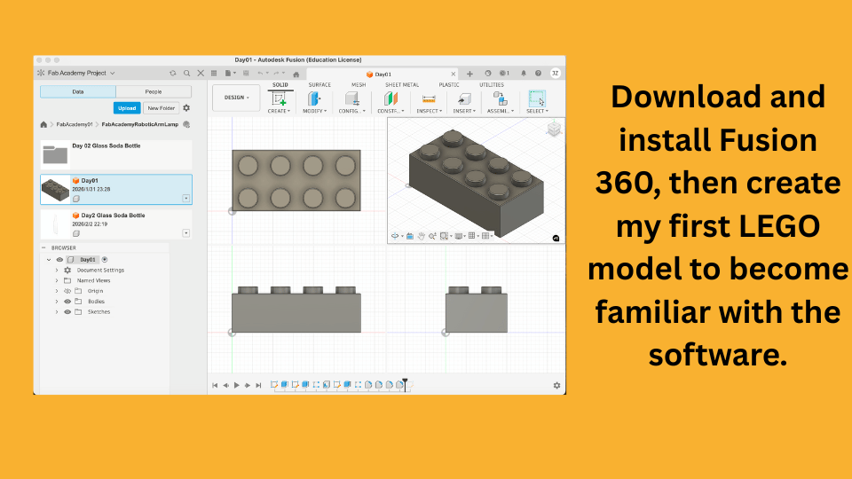
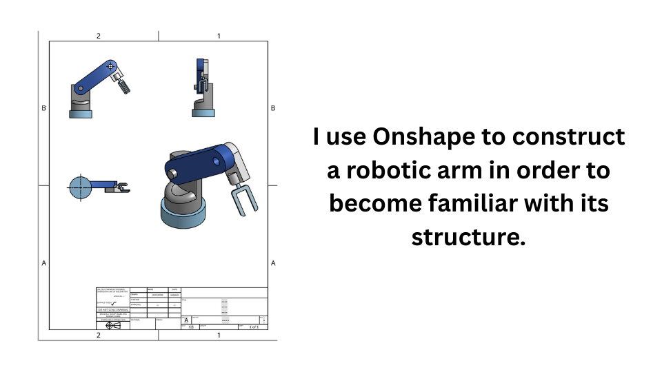
Fusion 360 Design
I started to design the 3D model of the robotic arm lamp using Fusion 360.
Onshape Design — Robotic Arm Step-by-Step
I also designed the 3D model of the robotic arm lamp using Onshape, following a structured parametric workflow. Below are the full steps I followed.
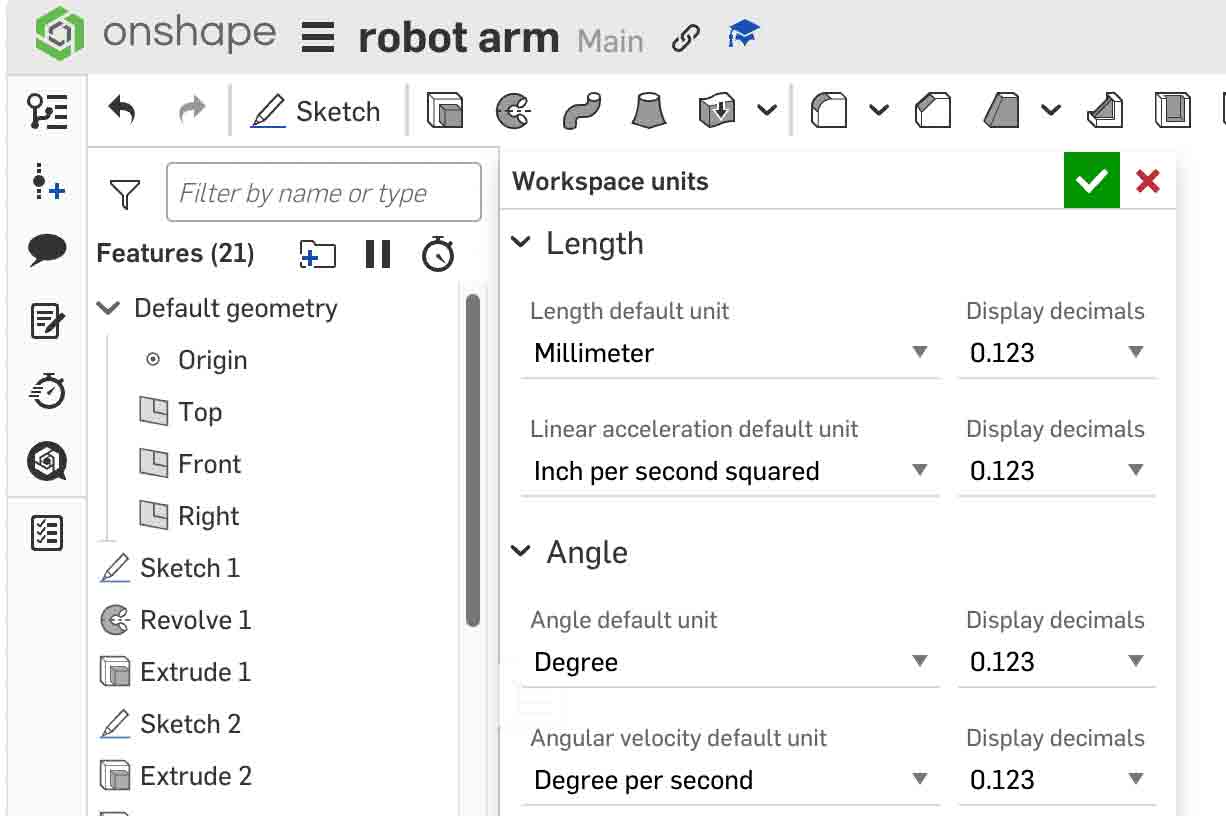
Step 1 — New Document & Set Units to mm
Go to onshape.com and click Create → Document. Name the document (e.g. Robotic Arm). Once inside the Part Studio, open File → Units and set all units to millimeters (mm). This ensures all dimensions remain consistent throughout the model.
Step 2 — Create a Layout Sketch
Before modeling any solid geometry, create a Layout Sketch on the Top Plane. This master sketch defines all critical dimensions — joint positions, arm lengths, and rotation centers. Use construction geometry (dashed lines) for reference lines so they do not generate solid faces.
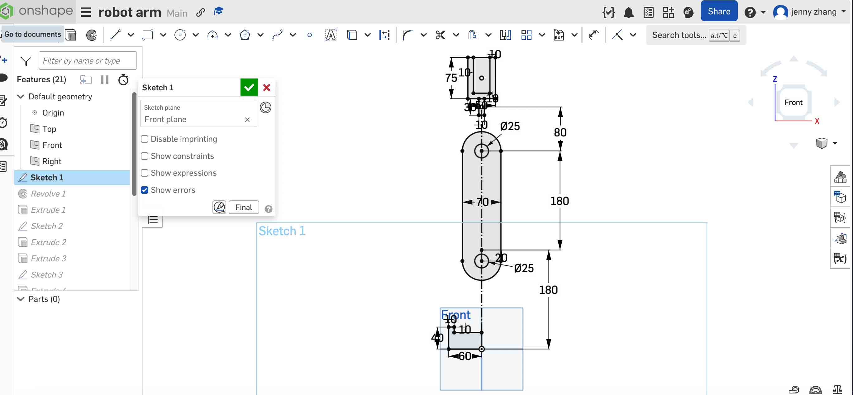
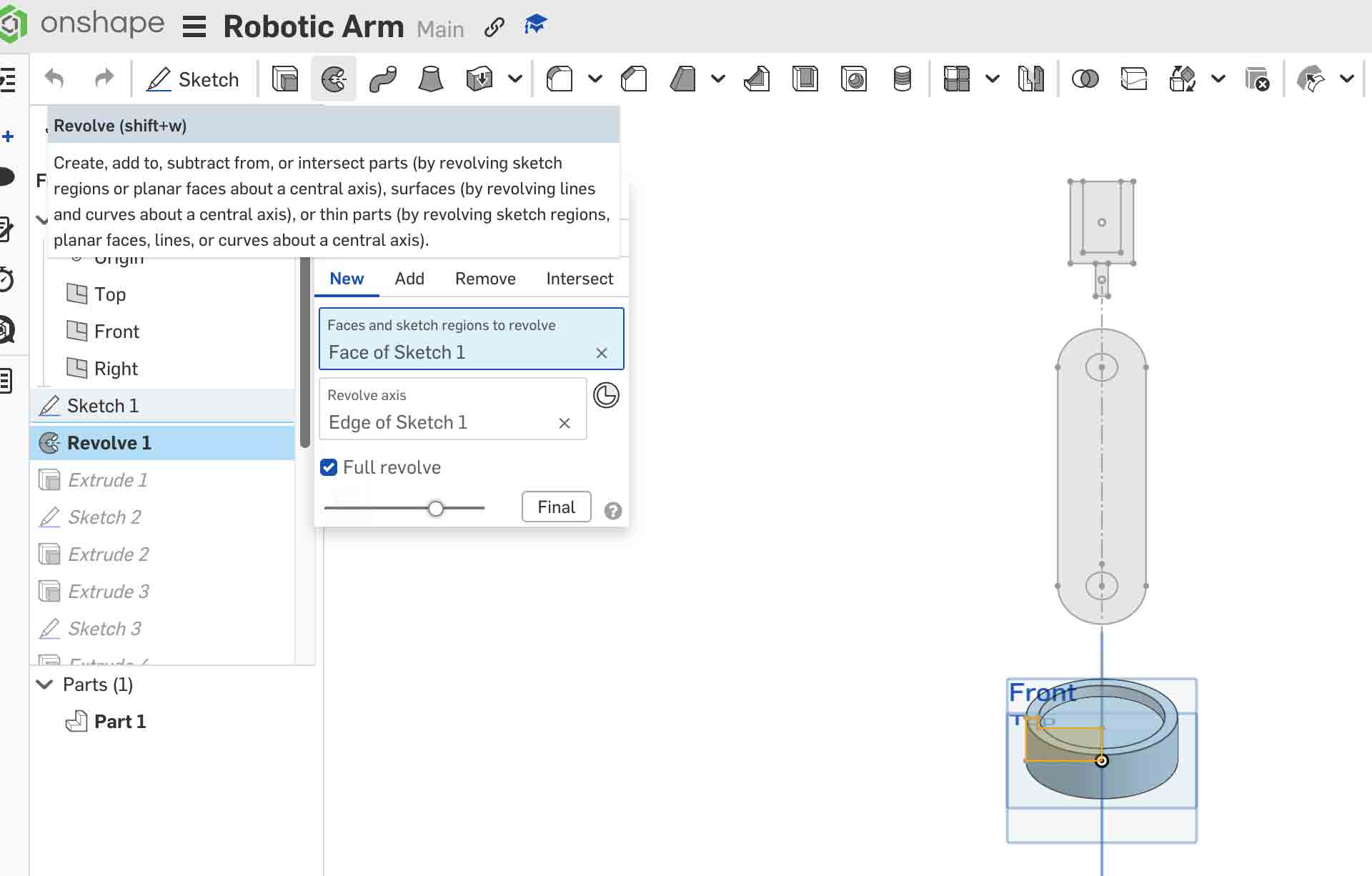
Step 3 — Light Blue Base (Revolve Feature)
Select the Front Plane and create a new sketch. Draw an L-shaped cross-section profile representing half of the base. Then apply Revolve → Full (360°) around the vertical centerline to produce a symmetrical cylindrical base.
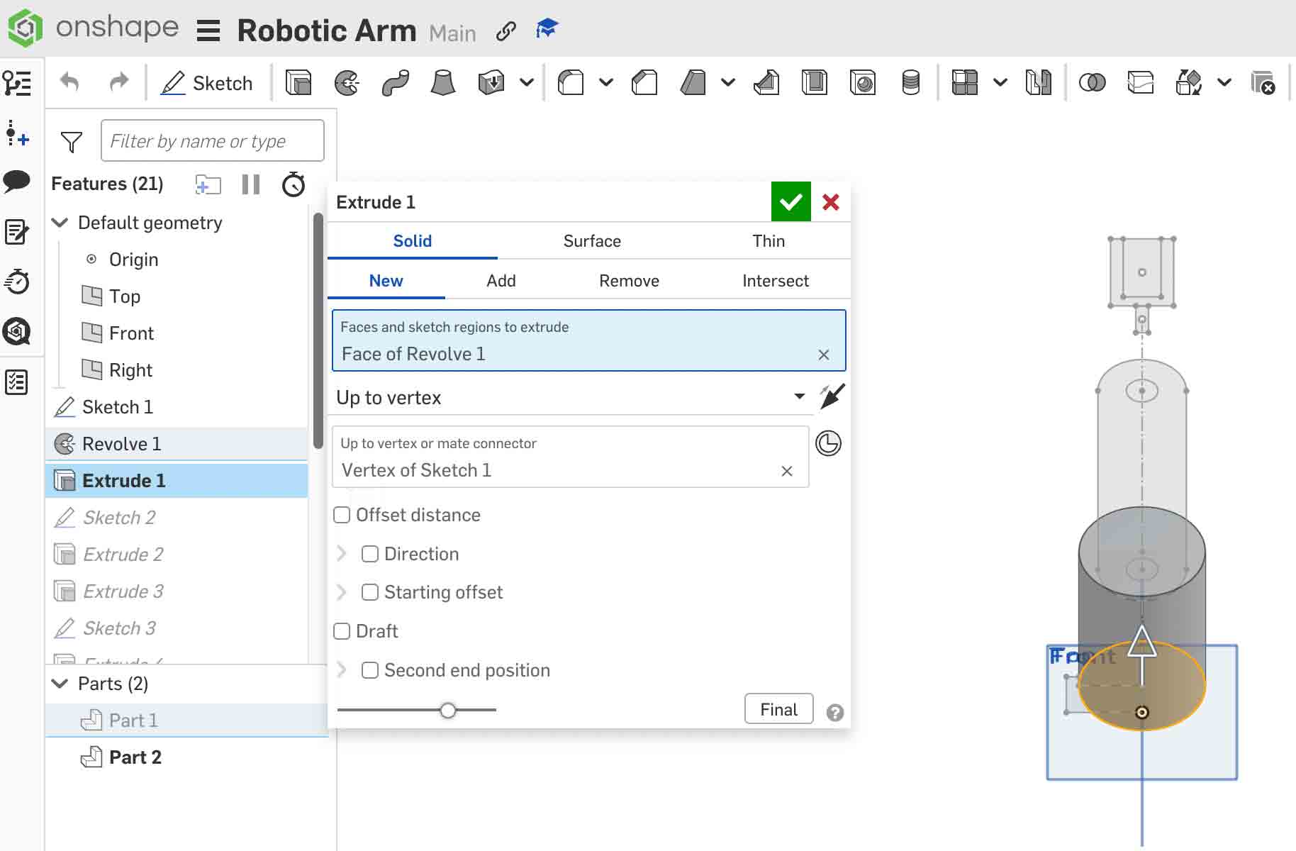
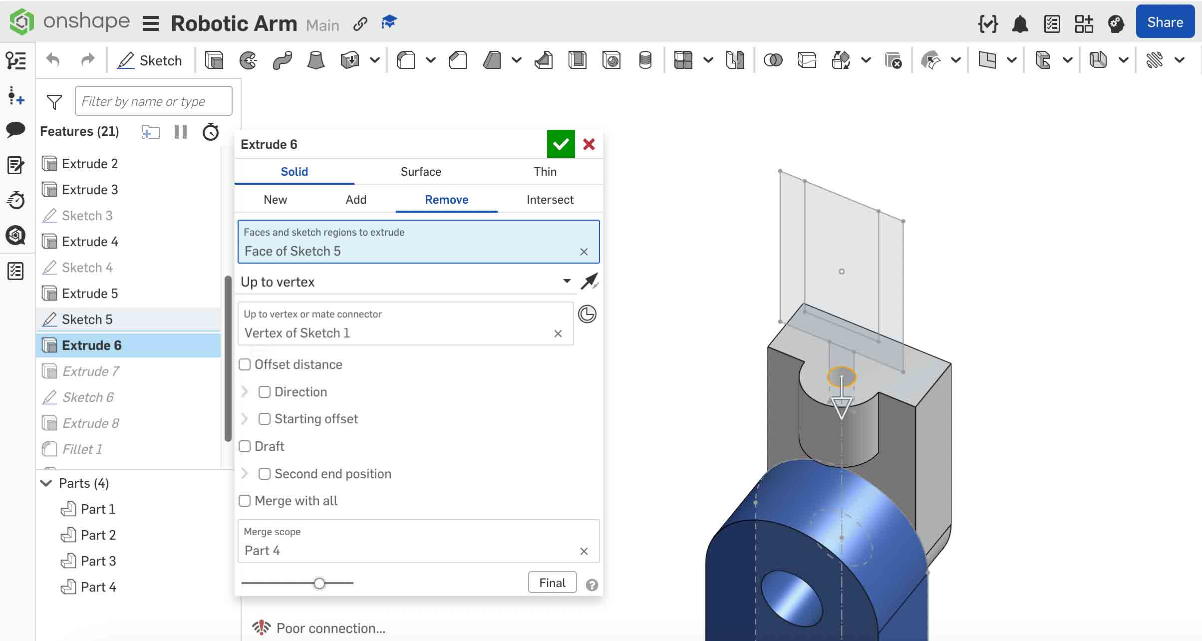
Step 4 — Dark Gray Arm (Extrude Up to Vertex)
Sketch the pill-shaped arm link profile on a face of the base. When extruding, instead of entering a fixed distance, change the End Type to Up to Vertex and click the target vertex from the layout sketch. This ties the arm's height directly to the layout — if the layout changes, the arm updates automatically.
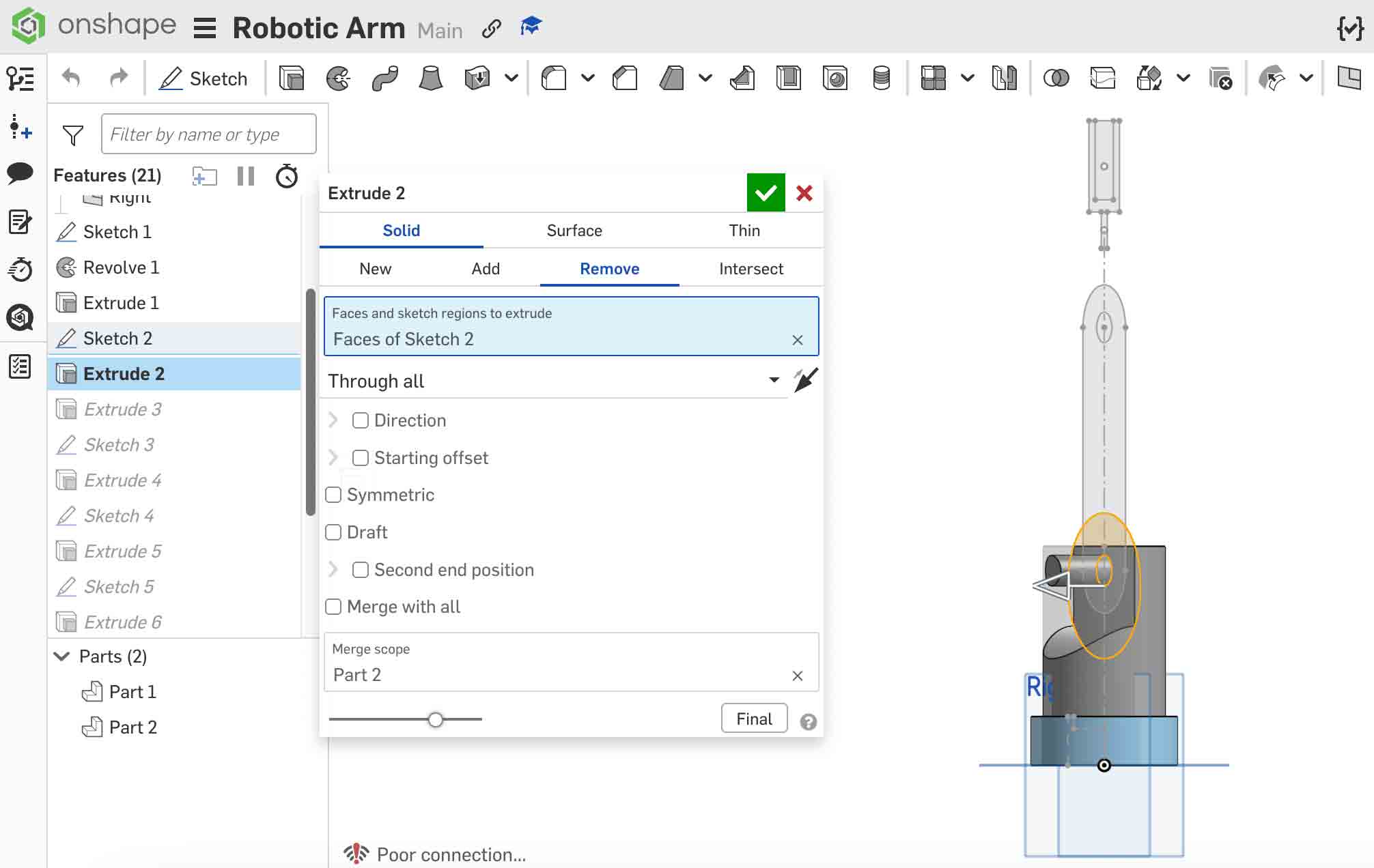
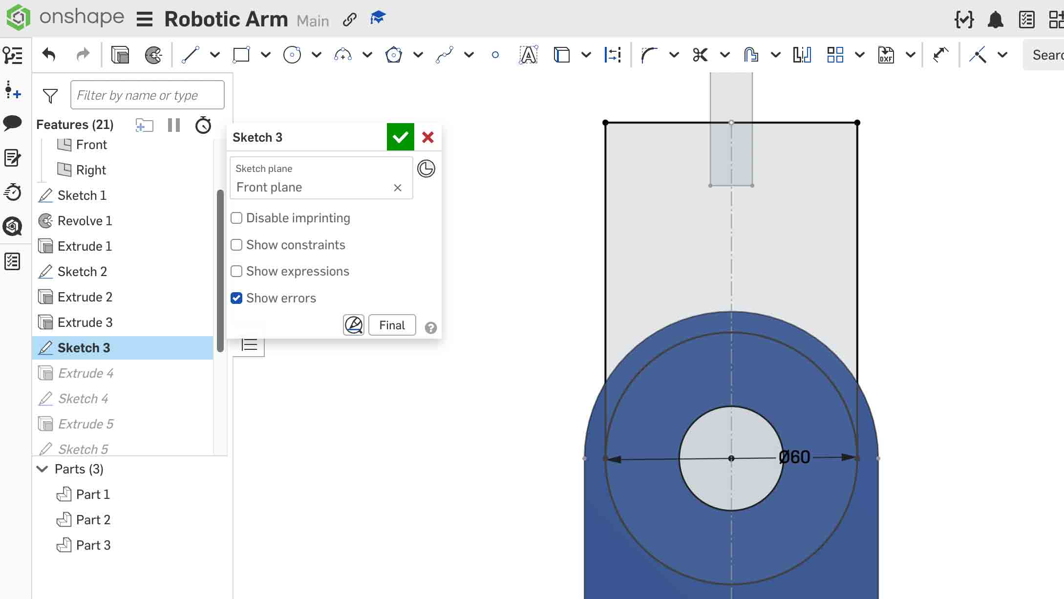
Draw a circle on the Front Plane and use Extrude → Remove to cut away a portion of the gray arm geometry, creating the joint opening.
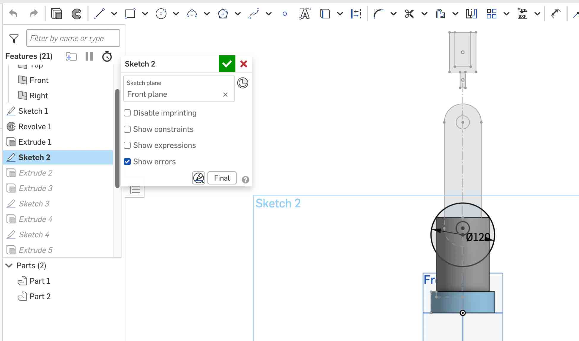
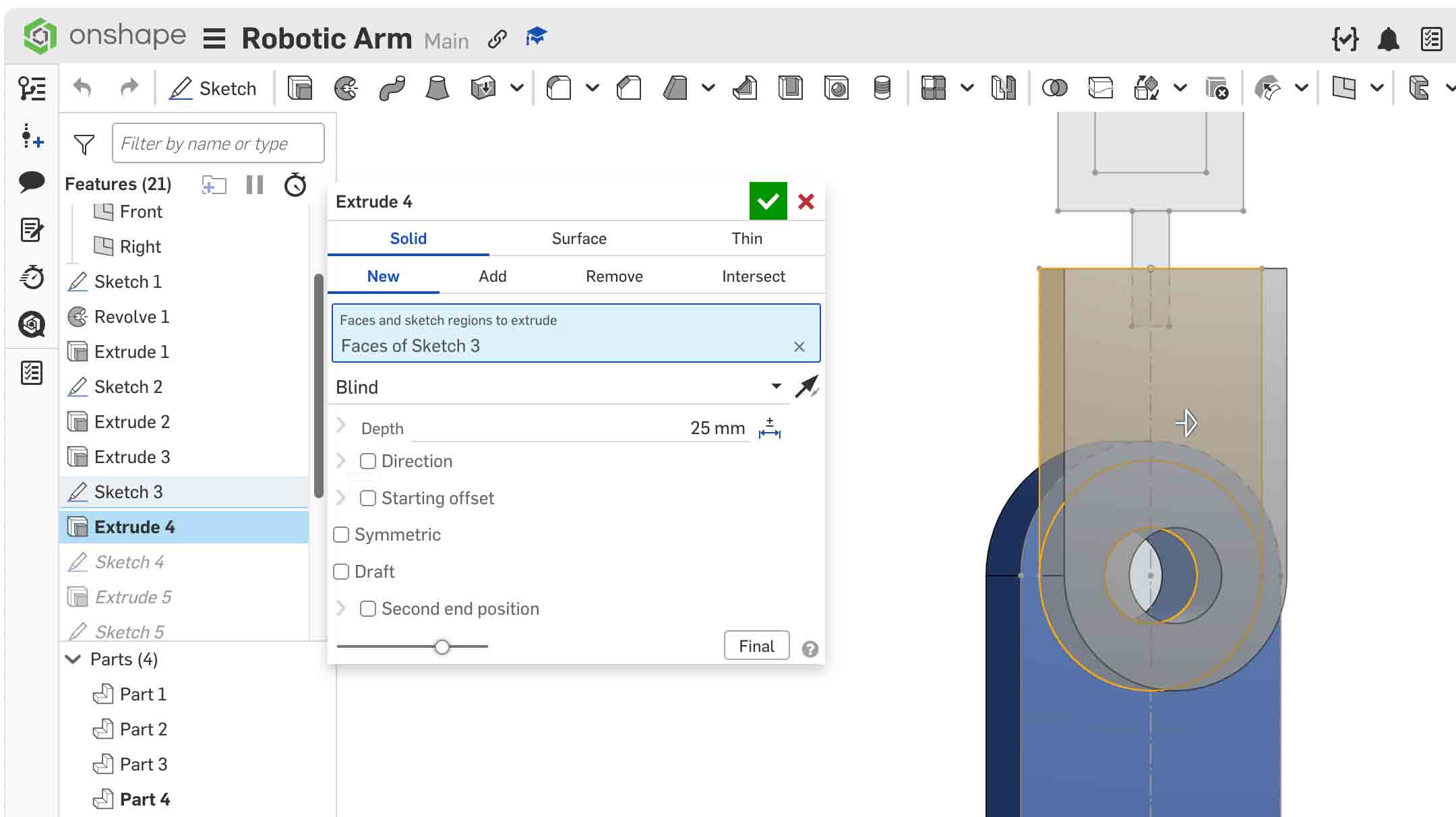
Step 5 — Dark Blue Link (Multiple Components in One Part Studio)
Sketch the link profile on an existing face, then use Extrude → New to create it as a separate part. Extrude to the required thickness to produce the Dark Blue Link component.
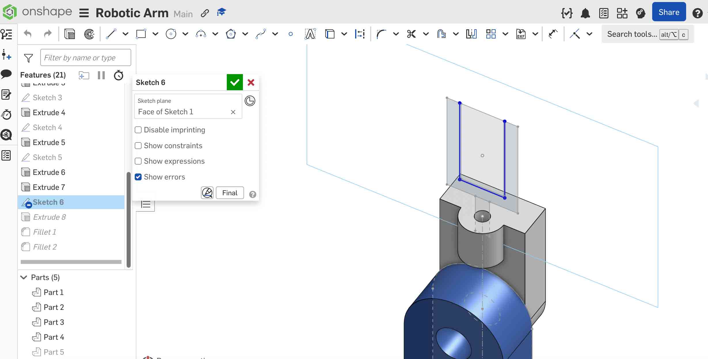
Step 6 — White Clamp Coupling (Referencing the Layout Sketch)
Create the clamp coupling by referencing geometry from the layout sketch. Use Use (Project) to bring layout sketch lines into the current sketch as references — this ensures the coupling stays aligned with the arm even if dimensions change. Extrude the profile to the required thickness.
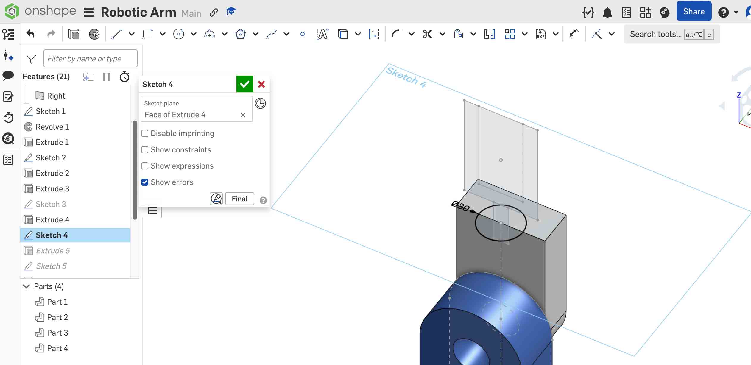
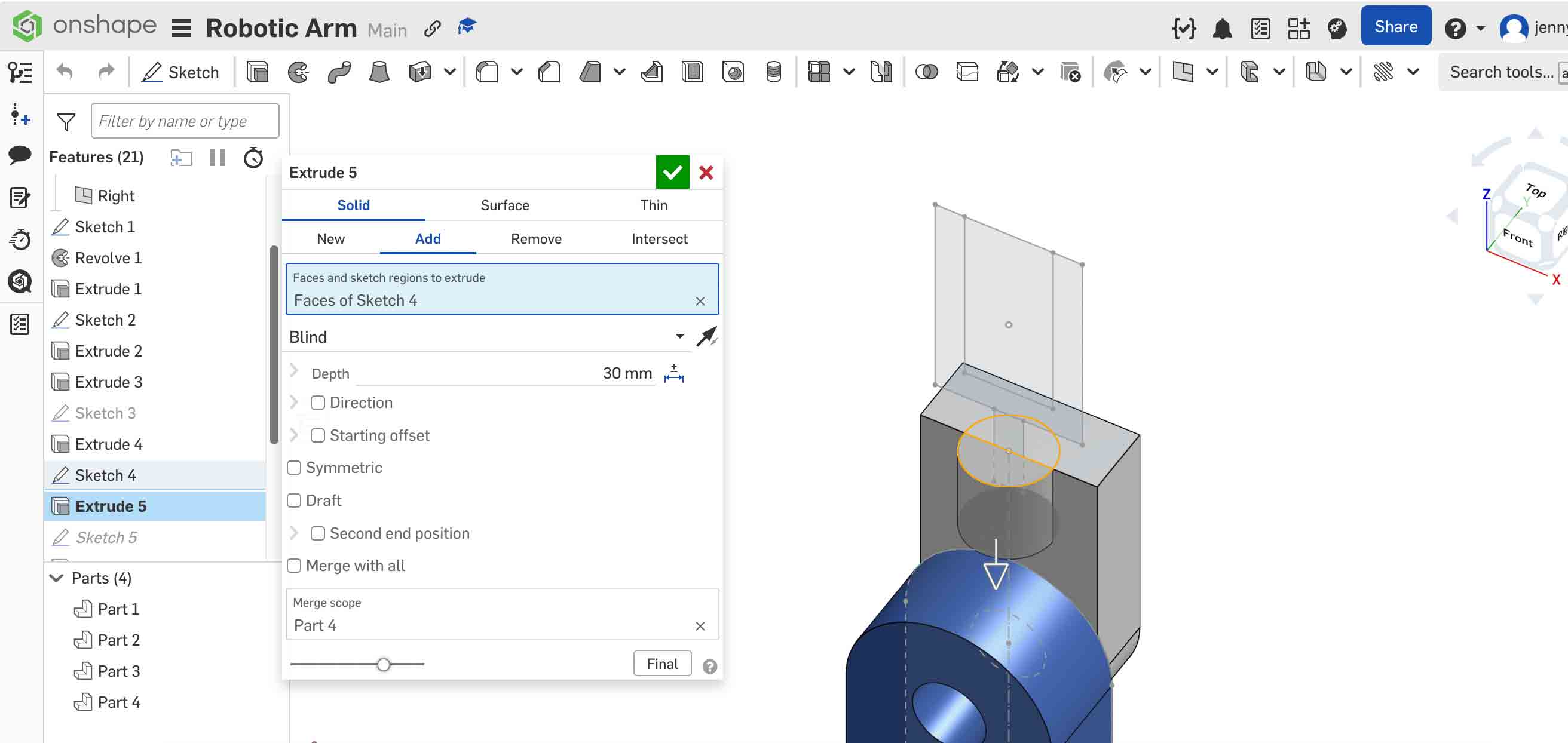
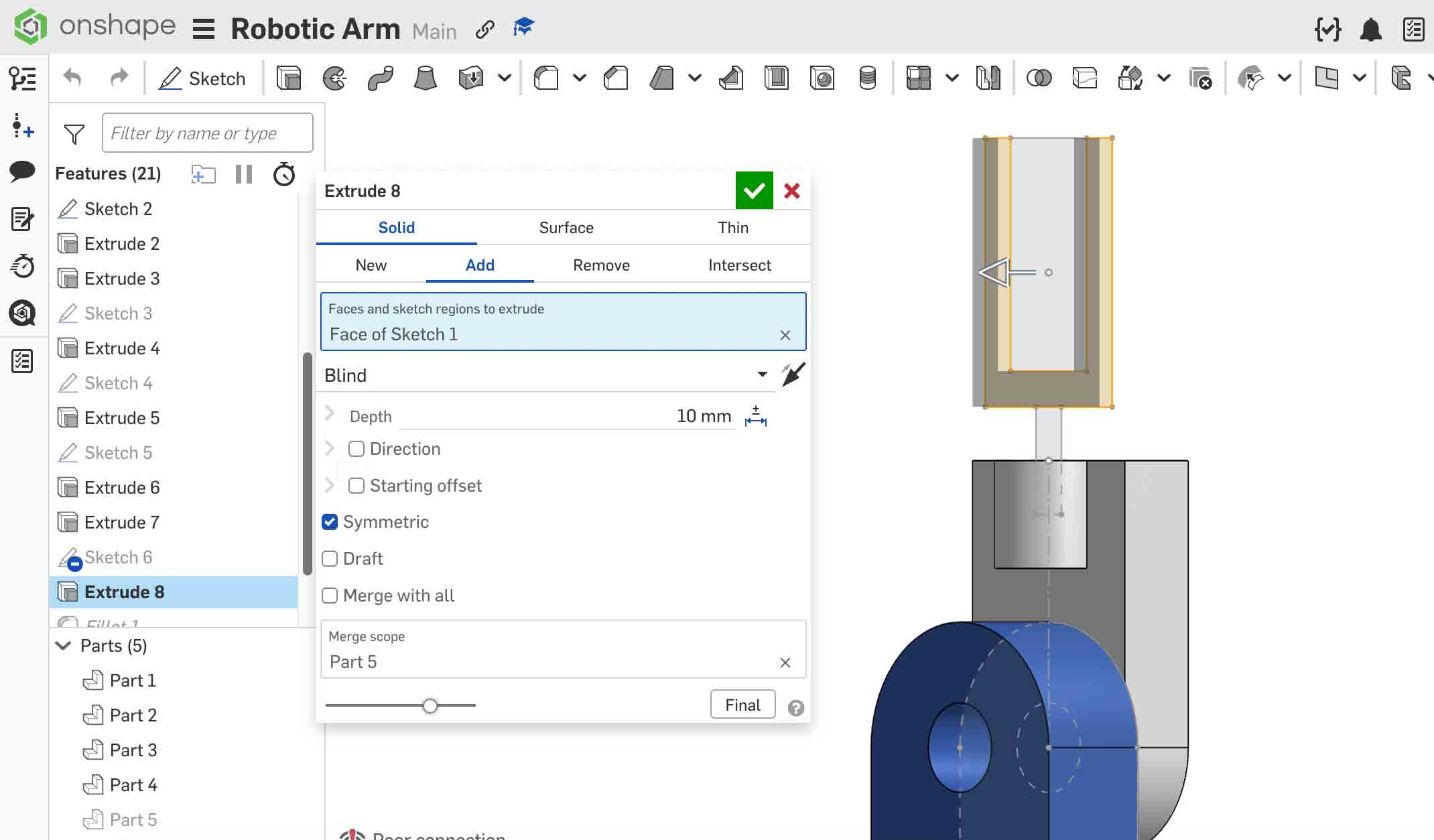
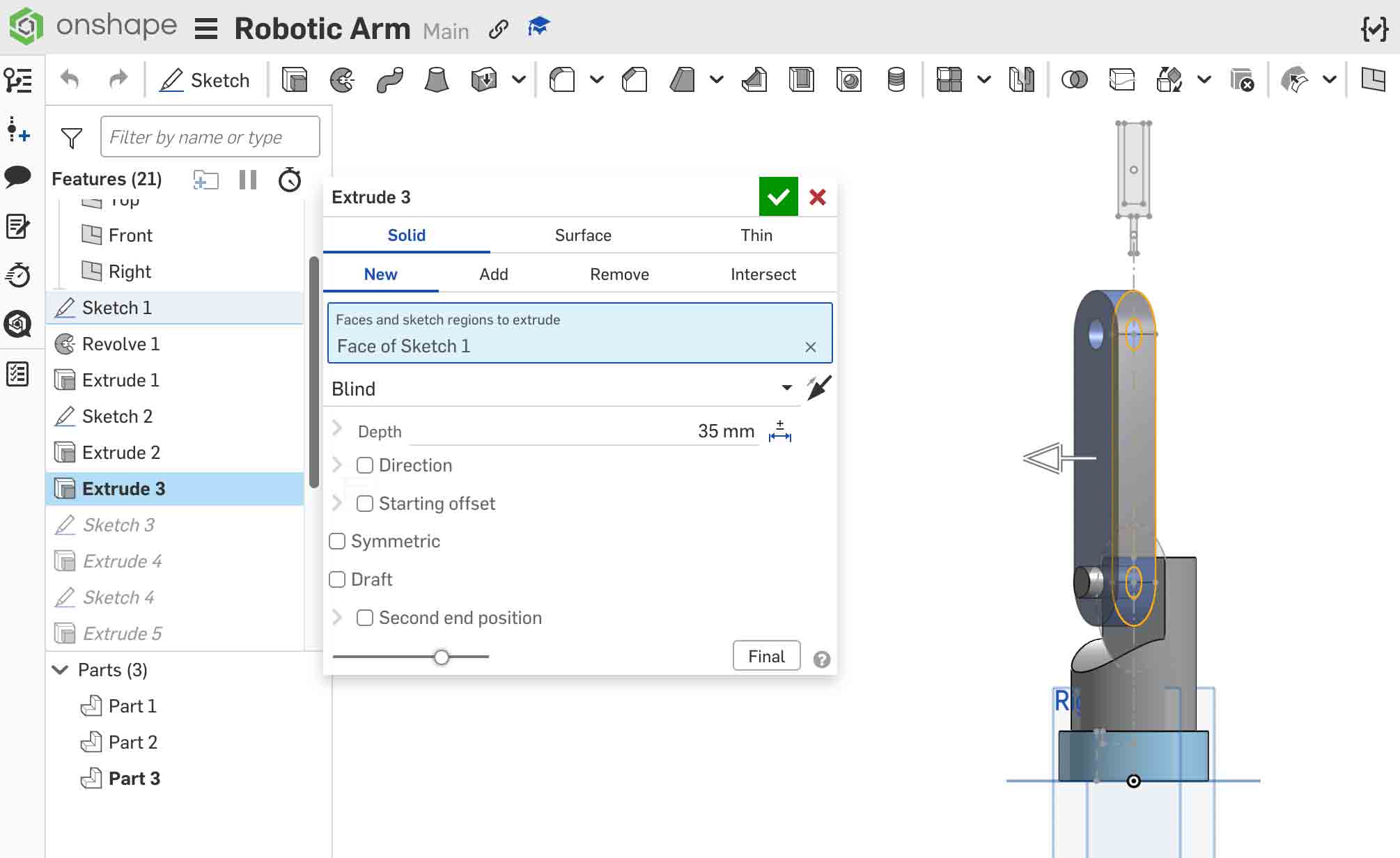
Step 7 — Clamp Part (Extrude Directly from a Face)
Rather than creating a sketch on a default plane, select an existing angled or offset face of the coupling as the sketch plane. Sketch the clamp jaw profile and extrude it to the required thickness. This technique avoids the need to manually offset planes and keeps all geometry anchored to the physical model.
- Click an existing part face to activate it as a sketch plane.
- Sketch the clamp jaw shape.
- Use Extrude → New to create it as a separate part.