Week 11:Networking and Communications
Assignments
Group Work : Send a message between two projects Document your work to the group work page and reflect on your individual page what you learned
individual assignments:design, build and connect wired or wireless node(s) with network or bus addresses and a local input and/or output device(s)
Group Work Assignment Reflection
Basics of hardware communications
Core Concepts: Parallel vs. Serial核心概念:并行 vs. 串行
Hardware communication is divided into two main categories based on the number of data lines:
| Type | Principle | Characteristics | Examples |
|---|---|---|---|
| Parallel Communication | Transmits multiple bits simultaneously using multiple data lines (e.g., 8 lines to transmit 1 byte at once) | Fast, but consumes many pins; crosstalk between lines worsens as frequency increases; unsuitable for long distances | Legacy printer parallel port (IEEE 1284), 8080 bus, NOR Flash parallel interface |
| Serial Communication | Transmits data bit by bit using one or two data lines | Fewer pins, lower cost, better noise immunity, easier to increase clock frequency; currently the mainstream approach | UART, I²C, SPI, USB, CAN, Ethernet |
Common Serial Hardware Communication Protocols
| Protocol | Number of Signal Lines | Synchronization | Direction | Typical Bit Rate | Network Topology | Typical Distance |
|---|---|---|---|---|---|---|
| UART | 2 (TX, RX) | Asynchronous | Full-duplex | 9600~115200 bps (up to several Mbps) | Point-to-point | Several meters (RS-232) ~ kilometers (RS-485) |
| I²C | 2 (SDA, SCL) | Synchronous | Half-duplex | 100k, 400k, 3.4M bps | Multi-master, multi-slave (address-addressed) | Tens of centimeters (on-board) |
| SPI | 4 (SCLK, MOSI, MISO, CS) | Synchronous | Full-duplex | 10~100 MHz (i.e., tens of Mbps) | Single-master, multi-slave (chip select) | On-board (< 30 cm) |
| 1-Wire | 1 (data line + ground) | Asynchronous (UART-like timing) | Half-duplex | 16.3 kbps (standard) | Single-master, multi-slave (unique ID) | Several meters (parasitic power) |
| CAN | 2 (CAN_H, CAN_L) differential | Synchronous (bit arbitration) | Half-duplex | 125k ~ 1 Mbps | Multi-master, multi-slave (priority arbitration) | Tens of meters to kilometers |
| USB | 4 (D+, D-, VBUS, GND) | Synchronous (NRZI encoding + clock recovery) | Half-duplex (Low/Full speed) or dual-simplex (High speed) | 1.5 Mbps ~ 20 Gbps | Host-device (star) | Several meters (standard cable) |
Classification Dimensions of Communication Methods
By Clock Synchronization: Synchronous vs. Asynchronous 按时钟同步方式:同步 vs. 异步
| Synchronous Communication | Asynchronous Communication | |
|---|---|---|
| Clock Signal | Has a dedicated clock line (SCLK); both sides sample data using the same clock | No clock line; both sides must agree on the same baud rate, and each byte has start/stop bits |
| Data Alignment | Hardware clock ensures bit synchronization | Aligned by the start bit; allows a certain clock error (typically <3%) |
| Communication Efficiency | High (no extra overhead bits) | Relatively low (2~3 overhead bits per byte) |
| Distance | Short (clock signal is susceptible to interference) | Longer (only data lines, suitable for several to tens of meters) |
| Examples | I²C, SPI, USART (synchronous mode) | UART (RS-232, RS-485), MIDI |
Individual Assignments
Communication Protocol Comparison
Before choosing a protocol, I compared the main options available on the ESP32 platform. The table below summarises the key characteristics of each method and explains why I selected ESP-NOW for this project.
| Method | Common Pins | Wired / Wireless | Typical Use | Speed | Range | Good For | Main Limitation |
|---|---|---|---|---|---|---|---|
| UART / Serial | TX, RX | Wired | Board-to-board, PC debugging, modules like GPS / DFPlayer | Medium | Short | Simple communication between two devices | Usually one-to-one |
| I²C | SDA, SCL | Wired | Sensors, OLEDs, RTC, multiple devices | Medium | Short | Many devices on just 2 signal wires | Short distance, address conflicts possible |
| SPI | MOSI, MISO, SCK, CS | Wired | Displays, SD cards, fast sensors, radio modules | Fast | Short | High-speed communication | Uses more pins |
| Wi-Fi | Built into ESP32 / ESP8266 | Wireless | IoT, web server, remote control, sending data online | Fast | Medium | Internet, phone / web dashboard | Higher power use |
| Bluetooth / BLE | Built into ESP32 | Wireless | Phone control, apps, nearby device connection | Medium | Short | Easy phone-to-board communication | Shorter range than Wi-Fi |
| Radio (RF) | Often via SPI modules | Wireless | Remote control, board-to-board wireless | Varies | Medium to long | No Wi-Fi needed | Needs extra module |
| CAN Bus | CAN TX/RX + transceiver | Wired | Automotive, robotics, robust multi-device systems | Medium | Long | Reliable in noisy environments | Extra hardware needed |
| ESP-NOW ✓ | ESP32 / ESP8266 wireless | Wireless | Direct ESP-to-ESP communication | Fast | Medium | No router needed, low latency | Mostly for ESP family only |
Why I chose ESP-NOW — and ruled out the alternatives
My project needs two ESP32 boards to communicate in real time: a button press on Board A must move the servo on Board B with no noticeable delay. Here is why I rejected each alternative:
- No router, no internet, no pairing.
- Very low latency and low power.
- Works over 200‑500 meters in open space.
- Perfect for remote sensors, wireless switches, or direct device‑to‑device control.
ESP-NOW wins because: both boards are already ESP32s (no extra hardware), the latency is less than 5 ms (servo feels instant), no router or infrastructure is needed, and the API is straightforward — register a peer by MAC address and call esp_now_send().
How ESP‑NOW Works
24:0A:C4:...)What is the first principle behind ESP-NOW?
At the most fundamental level, ESP-NOW works because two ESP32 boards use their built-in 2.4 GHz Wi-Fi radio hardware to send and receive specially formatted wireless frames directly, without needing a router or a normal Wi-Fi network connection.
So the core idea is:
ESP-NOW is not a completely different radio system.
It uses the same Wi-Fi hardware inside the ESP32, but instead of connecting to a router and using TCP/IP, it sends small direct packets from one ESP32 to another.
First-principles view: what is wireless communication?
- One device converts digital data (0s and 1s) into electromagnetic signals.
- Those signals are transmitted through the air using a radio frequency.
- Another device listening on the same frequency receives the signal.
- It converts the signal back into digital data.
For ESP32, this happens using its 2.4 GHz Wi-Fi radio. So when two ESP32 boards communicate with ESP-NOW, they are really doing this:
one ESP32 uses its antenna and Wi-Fi hardware to radiate a signal the other ESP32 listens for that signal if the message format matches ESP-NOW and the address matches, it accepts the data
Note: With normal Wi-Fi, you will need to use a router, connecting to a network, an IP address, and a full network protocol stack.
With ESP-NOW, you can just send short data directly.
How do two ESP32 boards communicate without a router
Normally, Wi-Fi communication looks like this:
Device → Router → Network → Another device
But ESP-NOW skips the router. Instead, it works more like this:
ESP32 A → direct wireless packet through the air → ESP32 B
So ESP-NOW is a peer-to-peer communication method. That is why it is fast and lightweight.
- Direct Peer‑to‑Peer Each ESP32 has a unique MAC address. One board adds the other’s MAC address as a “peer” – no access point or router is needed.
- No Handshake Unlike Wi‑Fi or Bluetooth, ESP‑NOW does not establish a connection. It simply sends small data packets (up to 250 bytes) directly to the target MAC address. This makes communication extremely fast (latency 1‑10 ms).
- How to set it up?
- Enable ESP‑NOW in the board’s code.
- Register the other board’s MAC address as a peer.
- Send data using
esp_now_send(). - Receive data using
esp_now_recv().
Circuit Design
Board A — Button Sender
A momentary push-button is wired between GPIO 4 and GND. GPIO 4 is configured with the ESP32's internal pull-up resistor, so it reads HIGH at rest and LOW when pressed. The built-in LED (GPIO 2) blinks to confirm each transmission.
Board B — Servo Receiver
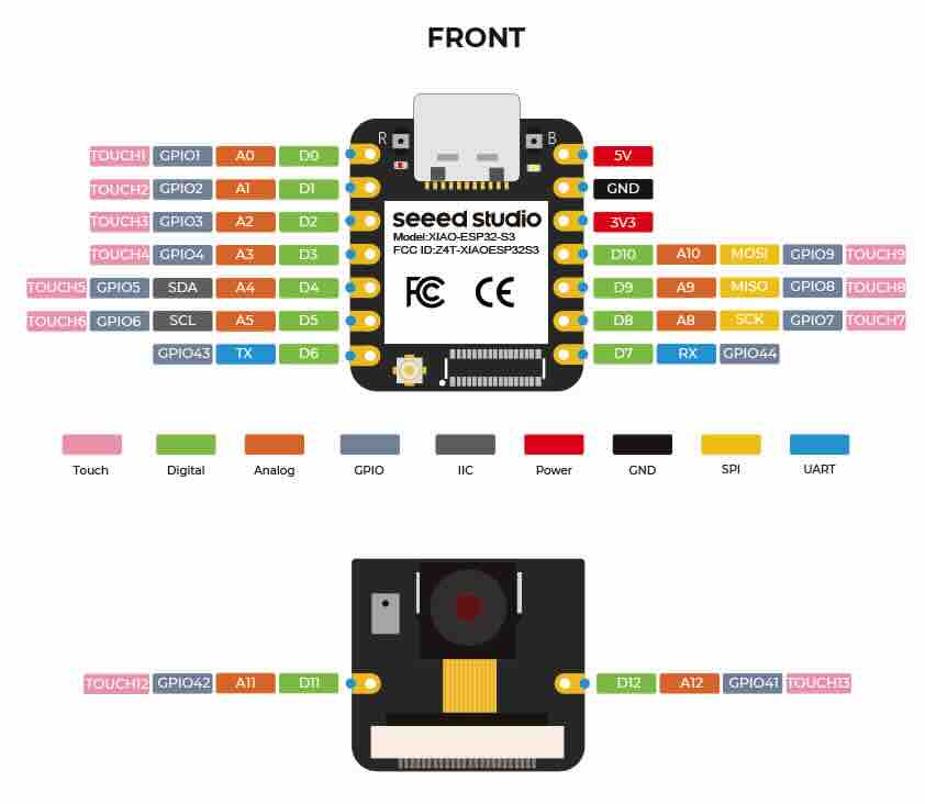
The SG90 servo signal wire is connected to GPIO 18, which supports LEDC PWM on the ESP32. The servo is powered from the board's 5 V pin (USB-sourced), with a 100 µF capacitor across the supply to absorb the inrush current when the servo stalls.
Step by Step
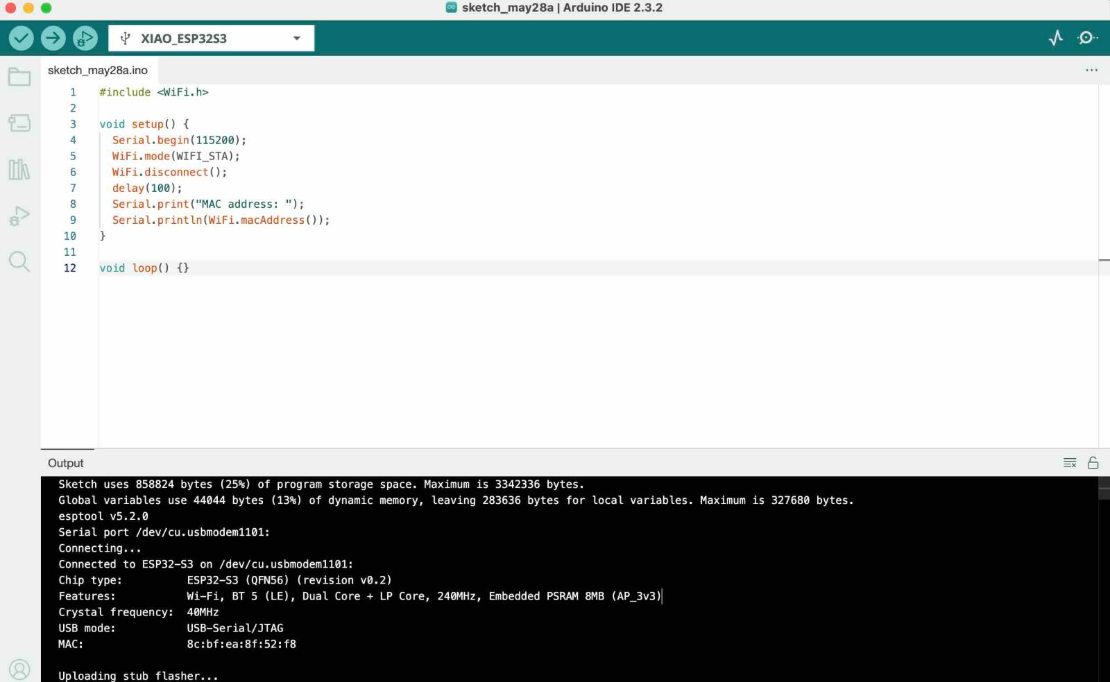
Before writing the code, you need to obtain the MAC addresses of the two ESP32 boards. Open one of the ESP32 boards in the Arduino IDE, enter the following code, run it, and note down the MAC address printed in the Serial Monitor.
                    #include

                        void setup() {
                          Serial.begin(115200);
                          WiFi.mode(WIFI_STA);
                          WiFi.disconnect();
                          delay(100);
                          Serial.print("MAC address: ");
                          Serial.println(WiFi.macAddress());
                        }

                        void loop() {}

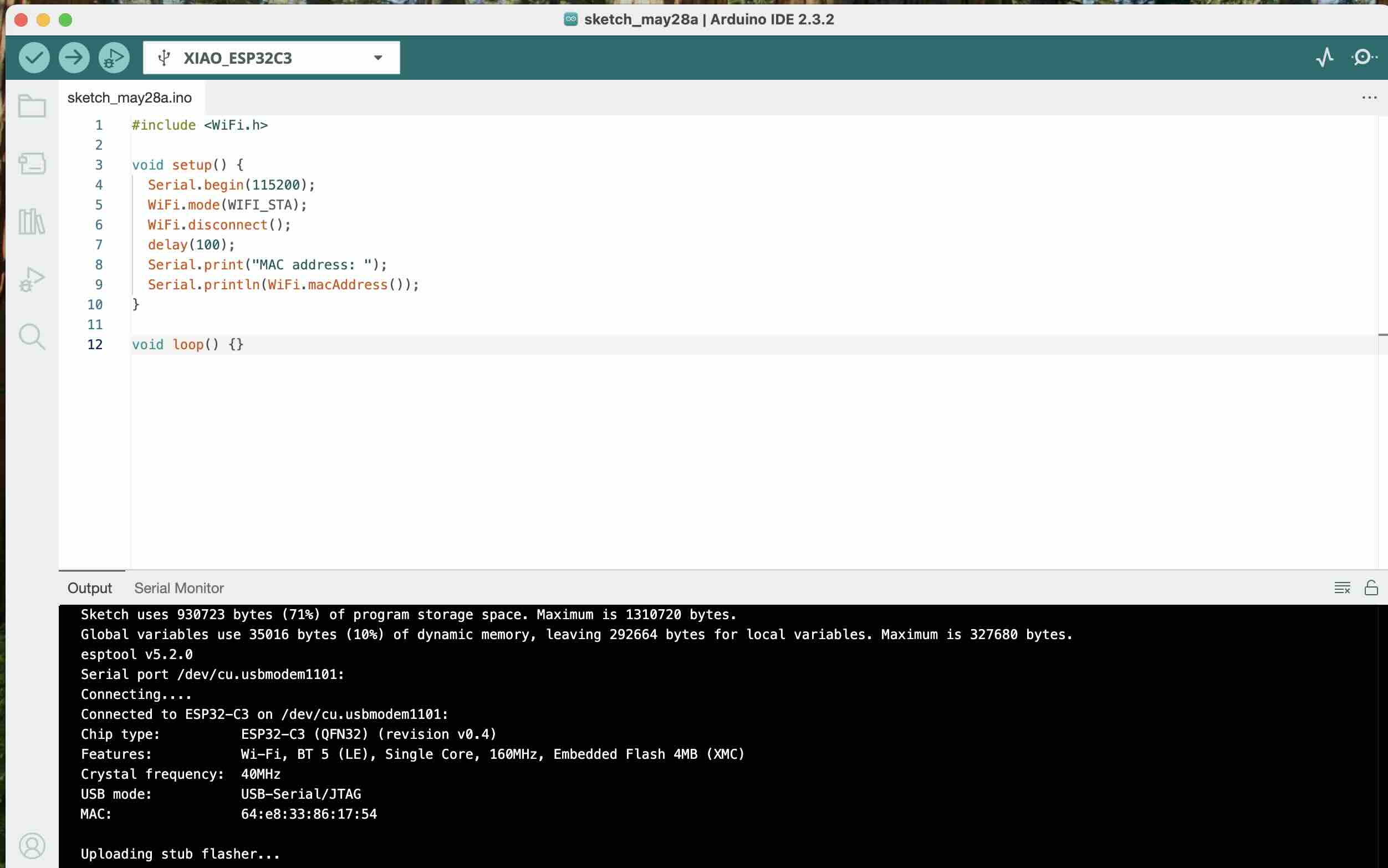
Sender's MAC address: 8c:bf:ea:8f:52:f8
Receiver's MAC address: 64:e8:33:86:17:54
Hardware Connection Quick Reference
Sender (XIAO ESP32-S3)
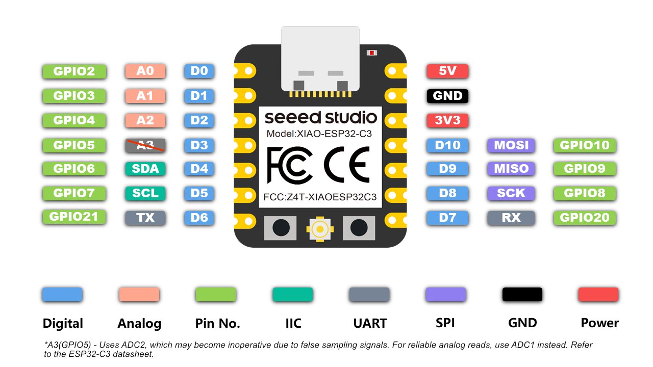
Button: one side connected to GND, the other side connected to GPIO 5.
Receiver (ESP32-C3)
Servo:
- Orange (signal wire) → GPIO 3 (supports PWM)
- Red (VCC) → External 5V power positive terminal
- Brown (GND) → External power GND (must be connected together with the GND of the ESP32-C3)
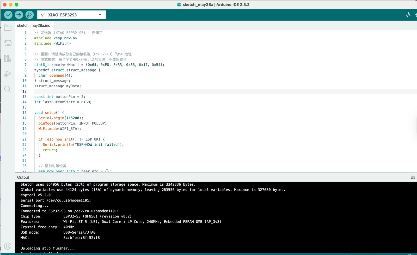
Sender's code:
Sender's MAC address: 8c:bf:ea:8f:52:f8
Button pin: GPIO 5 — connected with internal pull-up; already correctly configured.
Data structure:
The command field in the struct_message is responsible for passing the string commands "on" or "off" between the sender and the receiver.
// 发送端 (XIAO ESP32-S3) - 已修正
#include
#include
// 重要:请替换成你自己的接收端(ESP32-C3)的MAC地址
// 注意格式:每个字节用0x开头,逗号分隔,不要用冒号
uint8_t receiverMac[] = {0x64, 0xE8, 0x33, 0x86, 0x17, 0x54};
typedef struct struct_message {
char command[4];
} struct_message;
struct_message myData;
const int buttonPin = 5;
int lastButtonState = HIGH;
void setup() {
Serial.begin(115200);
pinMode(buttonPin, INPUT_PULLUP);
WiFi.mode(WIFI_STA);
if (esp_now_init() != ESP_OK) {
Serial.println("ESP-NOW init failed");
return;
}
// 添加对等设备
esp_now_peer_info_t peerInfo = {};
memcpy(peerInfo.peer_addr, receiverMac, 6);
peerInfo.channel = 0;
peerInfo.encrypt = false;
if (esp_now_add_peer(&peerInfo) != ESP_OK) {
Serial.println("Failed to add peer");
return;
}
Serial.println("XIAO ESP32-S3 Sender Ready");
}
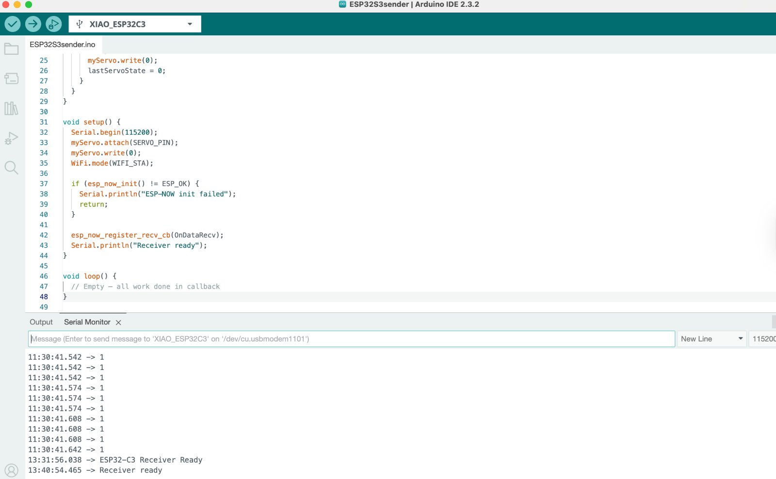
void loop() {
int currentButtonState = digitalRead(buttonPin);
if (currentButtonState != lastButtonState) {
delay(50);
if (currentButtonState == LOW) {
Serial.println("Button pressed");
strcpy(myData.command, "on");
esp_err_t result = esp_now_send(receiverMac, (uint8_t *)&myData, sizeof(myData));
if (result == ESP_OK) {
Serial.println("Command sent");
} else {
Serial.println("Error sending command");
}
}
lastButtonState = currentButtonState;
}
delay(10);
}
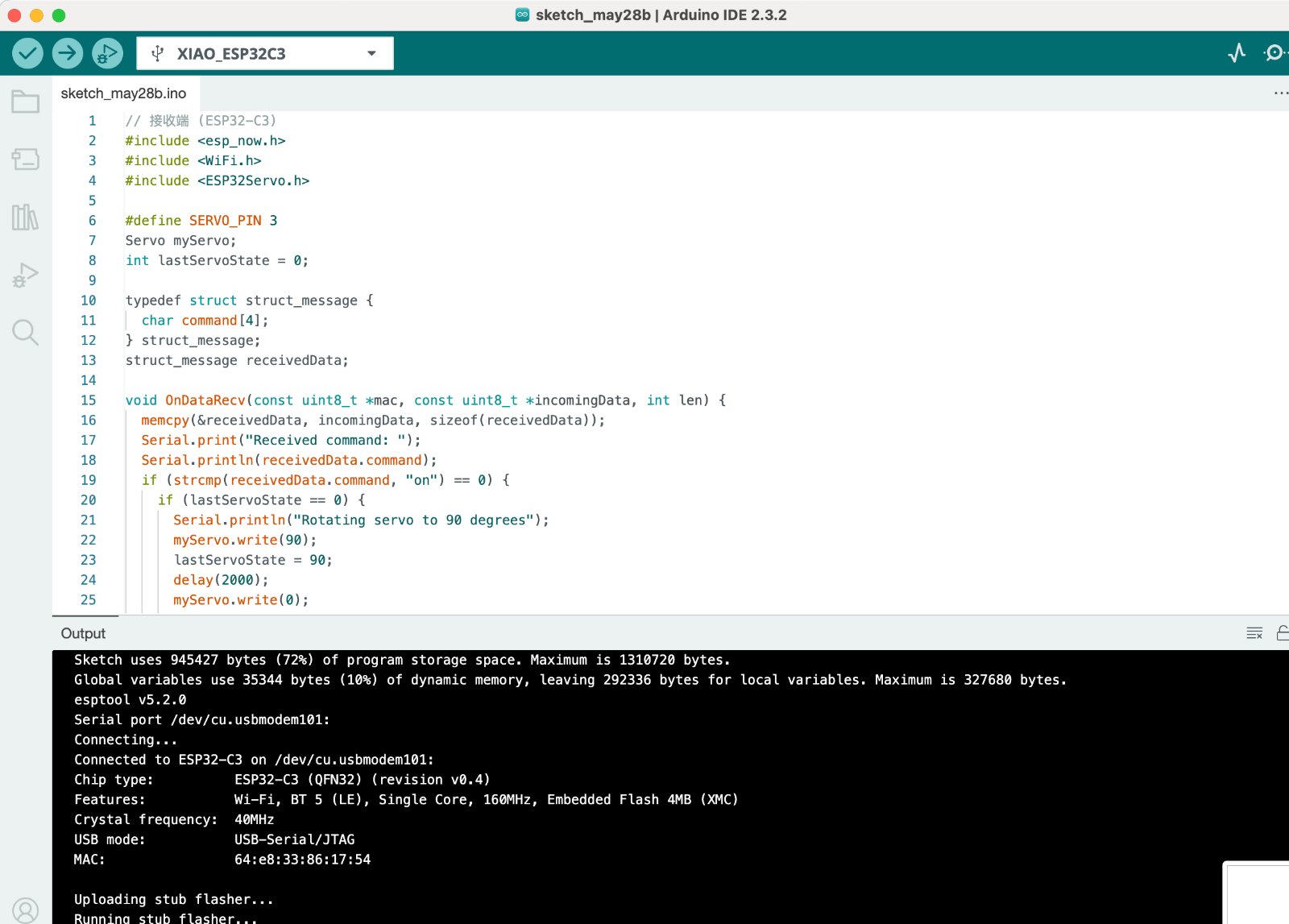
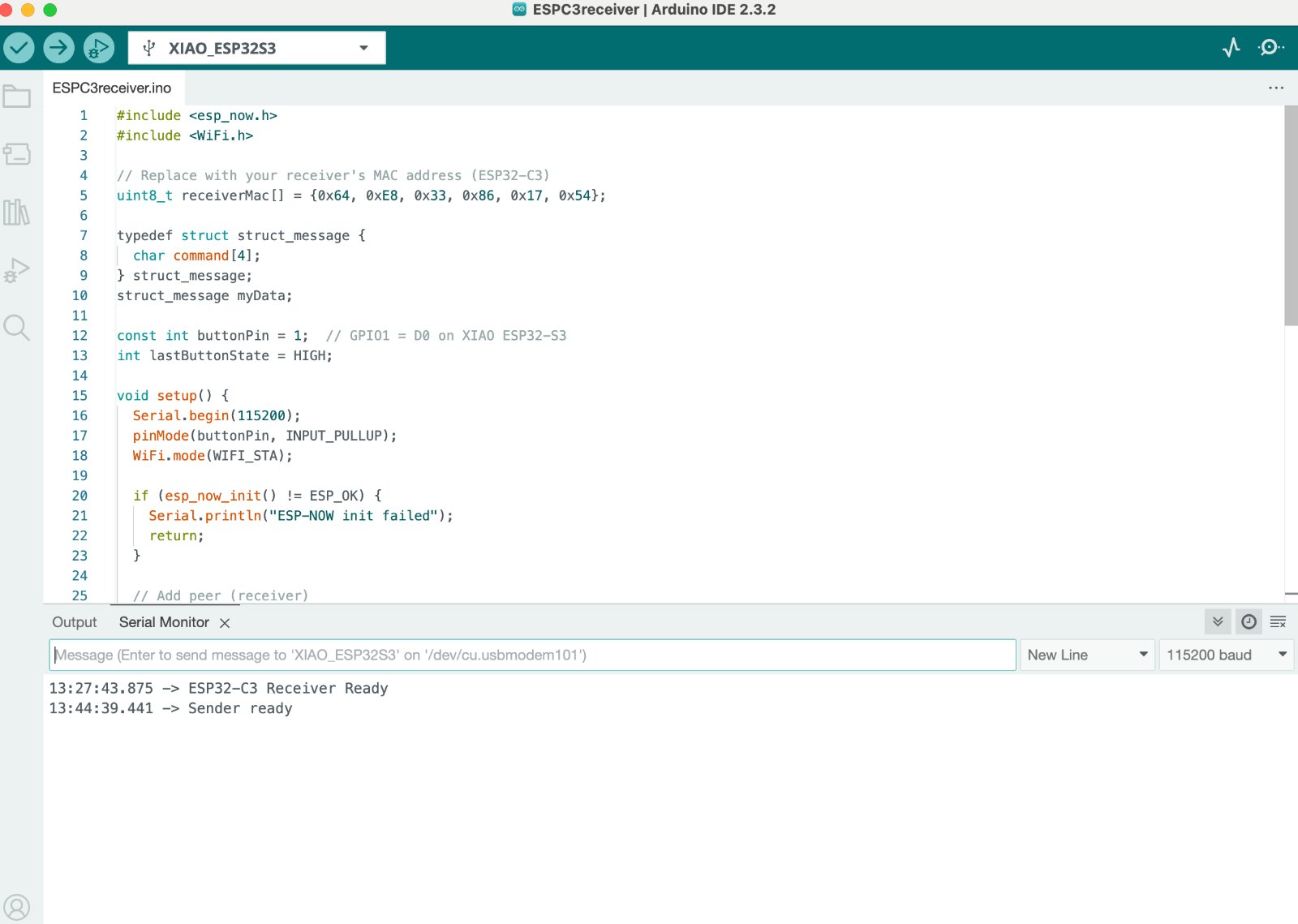
Receiver's code:
// 接收端 (ESP32-C3)
#include
#include
#include
#define SERVO_PIN 3
Servo myServo;
int lastServoState = 0;
typedef struct struct_message {
char command[4];
} struct_message;
struct_message receivedData;
void OnDataRecv(const uint8_t *mac, const uint8_t *incomingData, int len) {
memcpy(&receivedData, incomingData, sizeof(receivedData));
Serial.print("Received command: ");
Serial.println(receivedData.command);
if (strcmp(receivedData.command, "on") == 0) {
if (lastServoState == 0) {
Serial.println("Rotating servo to 90 degrees");
myServo.write(90);
lastServoState = 90;
delay(2000);
myServo.write(0);
lastServoState = 0;
}
}
}
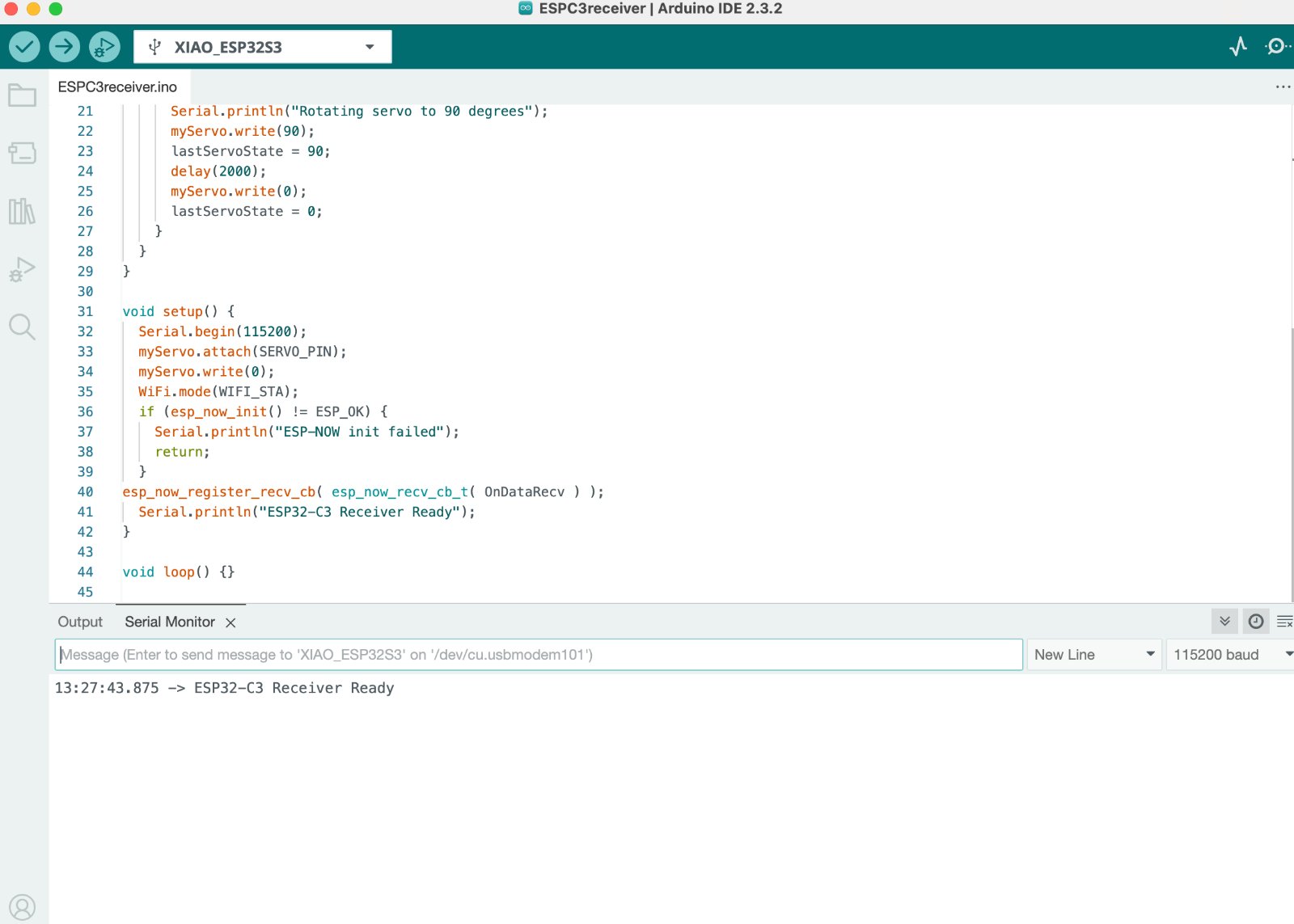
void setup() {
Serial.begin(115200);
myServo.attach(SERVO_PIN);
myServo.write(0);
WiFi.mode(WIFI_STA);
if (esp_now_init() != ESP_OK) {
Serial.println("ESP-NOW init failed");
return;
}
esp_now_register_recv_cb( esp_now_recv_cb_t( OnDataRecv ) );
Serial.println("ESP32-C3 Receiver Ready");
}
void loop() {}
Gallery
Also I tried to connect the ESP 32 C3 built in Wi-Fi capability to communicate wirelessly with smartphone.The Access Point Mode (AP) is a mode that allows the ESP32 creates it's own Wi-Fi network.
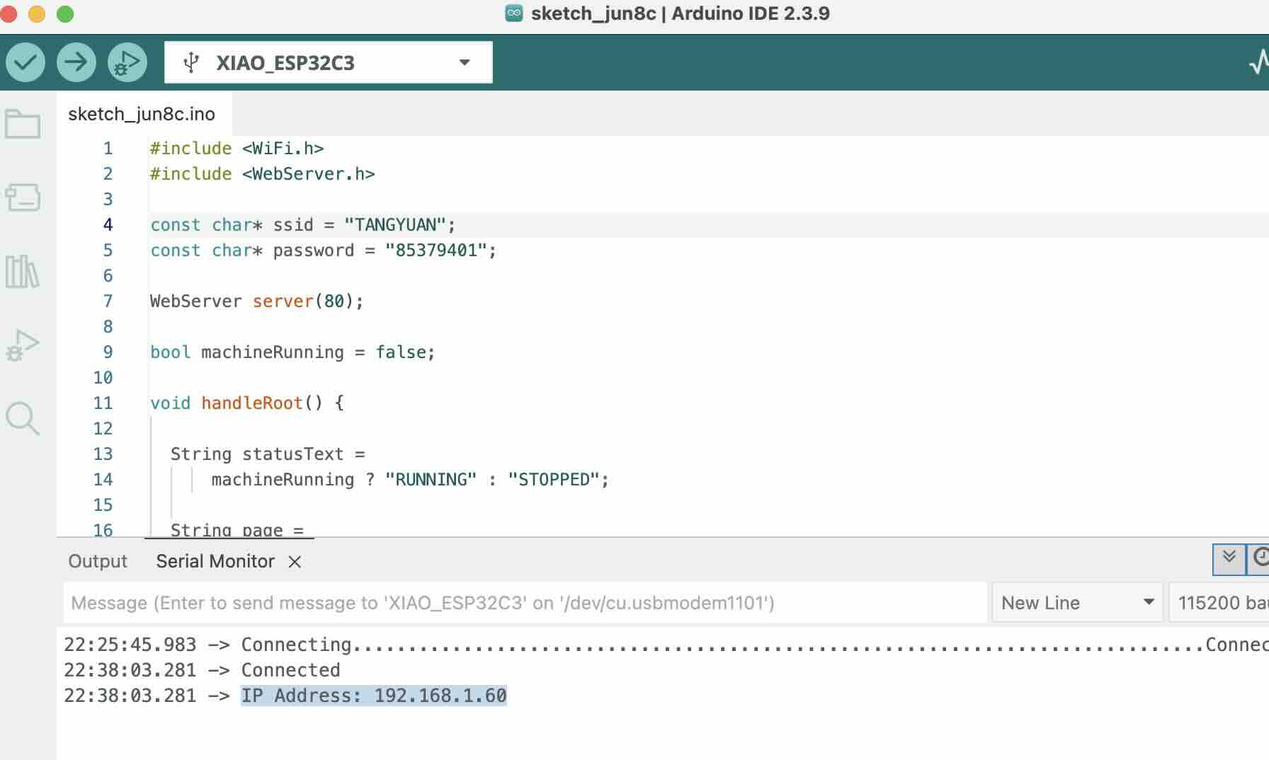
Step 1:Connect the ESP32 to a Wi-Fi Network,after that, you can check the IP address of the ESP32 C3 in the serial monitor and see if it is connected to the internet:
Step 2: Coding the AP mode,In AP mode, the ESP32 creates its own Wi-Fi network.
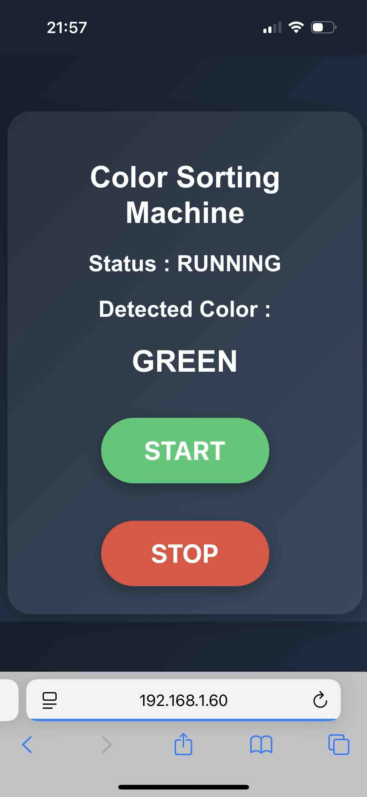
Step3: The ESP32 can host a web page and receive commands from a smartphone.
                    #include

                        #include
                            #include
                            #include
                            #include
                            #include

                            //================ WiFi ==================
                            const char* ssid = "TANGYUAN";
                            const char* password = "12345678";

                            WebServer server(80);

                            bool machineRunning = false;
                            String currentColor = "NONE";

                            //================ Servo ==================
                            #define SERVO1_PIN 2
                            #define SERVO2_PIN 3

                            Servo servo1;
                            Servo servo2;

                            //================ TCS34725 ==============
                            Adafruit_TCS34725 tcs =
                                Adafruit_TCS34725(
                                    TCS34725_INTEGRATIONTIME_50MS,
                                    TCS34725_GAIN_4X);

                            //========================================
                            // 颜色识别
                            //========================================
                            String detectColor()
                            {
                                uint16_t r, g, b, c;

                                tcs.getRawData(&r, &g, &b, &c);

                                if (c < 100)
                                    return "NONE";

                                float rf = (float)r / c;
                                float gf = (float)g / c;
                                float bf = (float)b / c;

                                if (rf > 0.45 && rf > gf && rf > bf)
                                    return "RED";

                                if (gf > 0.40 && gf > rf && gf > bf)
                                    return "GREEN";

                                if (rf > 0.30 && gf > 0.30 && bf < 0.20)
                                    return "YELLOW";

                                return "UNKNOWN";
                            }

                            //========================================
                            // Servo2 分类
                            // RED -> 30°
                            // GREEN -> 60°
                            // YELLOW -> 90°
                            //========================================
                            void sortBean(String color)
                            {
                                if (color == "RED")
                                {
                                    servo2.write(30);
                                }
                                else if (color == "GREEN")
                                {
                                    servo2.write(60);
                                }
                                else if (color == "YELLOW")
                                {
                                    servo2.write(90);
                                }
                                else
                                {
                                    return;
                                }

                                delay(500);

                                Serial.print("Sorted: ");
                                Serial.println(color);
                            }

                            //========================================
                            // Servo1送料
                            // 0° → 180° → 0°
                            //========================================
                            void feedBean()
                            {
                                // 正转
                                for (int pos = 0; pos <= 180; pos++)
                                {
                                    servo1.write(pos);
                                    delay(10);
                                }

                                delay(500);

                                // 回位
                                for (int pos = 180; pos >= 0; pos--)
                                {
                                    servo1.write(pos);
                                    delay(10);
                                }

                                delay(500);
                            }
Check the IP address of the ESP32 C3 in the serial monitor and see if it is connected to the internet and press the button to control the servo:
Note: when you connect the Wif-fi, you should keep the iphone and the ESP32 C3 in the same room, otherwise, the connection will be lost.And the wifi should be connected to the 2.4 GHz not the 5 GHz.
Problems Encountered and How They Were Fixed
- ESP32 could not connect to Wi-Fi the connection was lost. I found that the wifi should be connected to the 2.4 GHz not the 5 GHz.and the iphone and the ESP32 C3 should be in the same room.
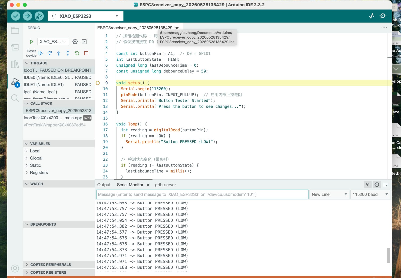
- When I pressed the button, the servo did not move. I found that the button was not connected to the ESP32 C3 correctly.
- Color sensor sometimes failed to recognize colors, Adjusted the RGB threshold values and added delays to stabilize the sensor readings.