Software & Tools
Adobe Illustrator
Vector Illustration, Layout, Typography
Version 30.1
Adobe Creative Cloud Subscription


Houdini
Procedural Modeling, Simulation, Rendering
Build 21.0.440
Houdini Apprentice

Gallery
Overhead Test
Final Result
Press-Fit Joint
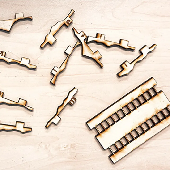
Puzzle Parts with Order Engraving
How to: Houdini Parametric Design
Step 1
Press Tab and search for Box. Now you can see the Box parameters like size, rotation, and scale. We want the Box to always sit on the ground plane, so we need to move it upward by half its size. Create a Transform node, which allows us to move the object. Right-click the Box’s Y Scale and choose Copy Parameter, then go to the Transform Y Position, right-click, and select Paste Relative References. This turns the field into an expression, which lets you enter code and channel references (you can see that via the green highlight). Since the Box should move up by half its Y Size, add /2 after the channel reference. This takes the Y Size of the Box and calculates half of it.
Step 2
Now we want to control another object with our Box’s Y Size. Add a Line and take the Box’s Y Scale reference and put it into the Line’s Length. You can still change any other parameter that isn’t referenced on your geometry. For example, you’re free to move the Line a little to the right.
Step 3
Next, we add a referenced number of copies based on how big our cube is. Take another Line, set its Direction to -X, and set the length to the desired size. Add a Copy Transform node, which lets you copy any object and transform it in the same step. For example, you can say that every clone should be placed 1 unit above the previous one. Instead of a fixed amount, we can use references. We can dynamically set both the distance between objects and the number of objects copied. Set the amount to the Box’s Y Size reference and divide it by the desired gap between the individual lines. Since we always have one line anyway, add +1 to the calculated amount. And because we want the line to be created only when the size is reached, add a floor() function so the calculation doesn’t round up. The full formula should look like this: floor(ch("../SETTINGS/height") / ch("ty") + 1).
Step 4
You can also drive strings or text with expressions. To explore that, add a Font node. Instead of writing text manually, we want to insert the dynamic height of our cube. Right-click on the text field and choose Relative References. Houdini will automatically add backticks, which tell the program that the text field contains an expression. After the backticks end, you can continue with normal text. For example, add “m” and you’ll have a dynamic measurement for your scene.
Done
This is how you can easily work with parameters and references in Houdini. You can collect all these parameters in a null and control your complete object from a single point. Of course, relative references can be used far beyond that. You can build fully functional tools based on each step and create long chains that generate your desired object in no time—and in any variation you want it to be. A bigger example follows in the next section. Well done!
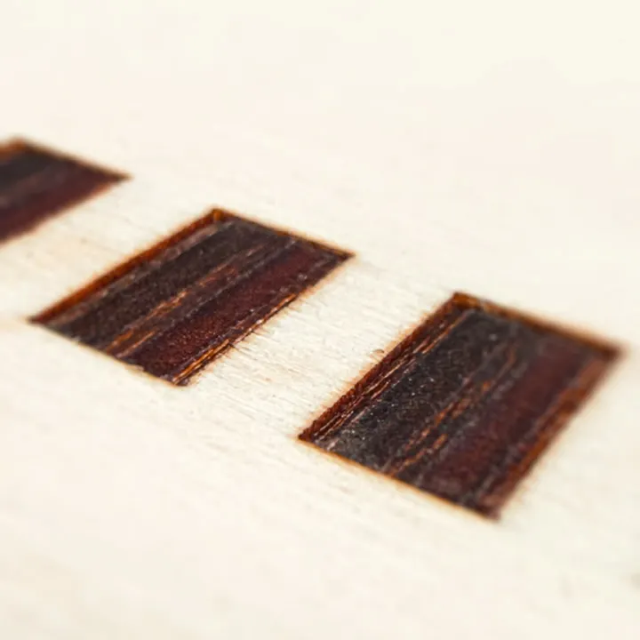
Accounting for Kerf
The kerf refers to the amount of material that is removed during the cutting process by the laser, and it represents the width of the laser beam. Even though the laser may appear to be very thin, it still has a measurable width, which is the kerf. The width can vary depending on factors such as laser power, material type, and settings like speed and focus. It’s important to account for the kerf when designing parts that need to fit together precisely. Typically, the kerf offset is half of the total kerf, as only one half of the kerf (from the cut edge) is relevant to the final fit. Designers often adjust their CAD files by either expanding or shrinking the dimensions of the parts to compensate for this offset, ensuring proper fit and functionality.


You can find the detailed kerf test on our Group Page.
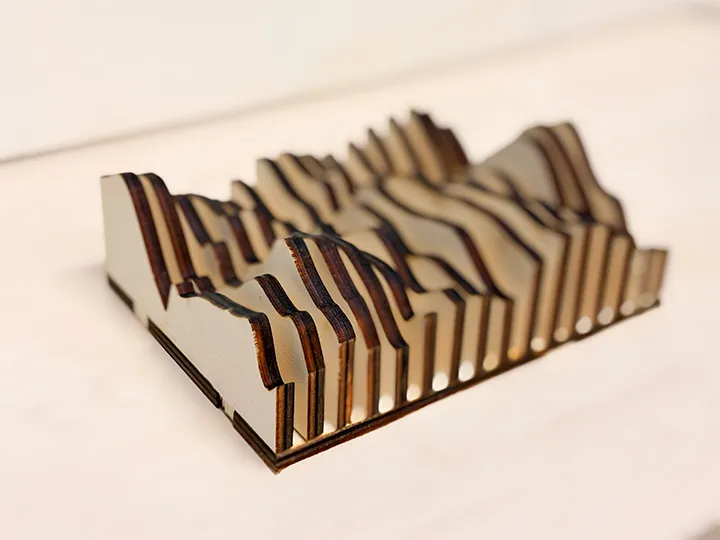
Parametric Construction Kit
Wall Panel Creator
For my major assignment for this week, I decided to create a Wooden Wall Panel with a noise-like design, or rather—since it needs to be parametric—I will create wall panels with any design imaginable. In simple terms, my weekly task is to build a tool that allows the user to input dimensions for a wall panel, creates a shape of the desired size, specifies the laser cutter's working area and material, and voilà, the finished SVG files are immediately available in the project folder.
For this, I used Houdini. Above, you can see the basic structure of the parametric workflow in Houdini. To create the Wall Panel Maker, of course, I needed a few more parameters. To give you an idea of the "behind the scenes" of the project, here's a breakdown of how I set it up.
Available Parameters:
- Wall Panel Size [mm]: X and Z dimensions of the panel.
- Shape Resolution: Resolution of the projected design.
- Feet Width [mm]: Width of the joint connection for fitting pieces together.
- Cut Operation:
- By Count: Define how many shapes will be placed on the wall panel.
- By Gap [mm]: Define the gap between the shapes on the panel.
- Material Thickness [mm]: The thickness of the material to be used.
- Cutting Board Size [mm]: The size of the material on which the cut will be divided.
- Kerf [mm]: The width of the kerf to be accounted for when creating the files.
- Shape Piece Padding [mm]: Distance between the individual elements when exporting.
Custom Shapes
In addition to these settings, there is, of course, the option to modify the noise pattern itself and thus change the design. Houdini already has built-in functionality to create and control noise through the UI, but in addition to the noise pattern, the shape of the wall panel can be modified in any way. To make changes to the shape, simply double-click on the Wall Panel node (the Wall Panel Tool) and you can adjust any part of the shape that will be exported.
Here’s an example of what’s possible and how the changes were made.
Exporting
For exporting as an SVG, I created a few smaller tools in Houdini. Although the direct export to SVG was significantly modified, it was based on a tutorial from Entagma, a Houdini—and now also Blender—tutorial channel, which I highly recommend for their high-quality videos. The tutorials are very clear and perfect for anyone wanting to work with more technical aspects.
Cut & Done
The next step is the actual cut. Everything is already prepared, and the SVG just needs to be opened in the cutter software of your choice. From there, you can set engraving and cutting settings based on the material you're using.

As learned during the safety training, fire extinguishers are located at most of the pillars around the lab. Before using machines like the laser cutter, it's essential to familiarize yourself with the emergency exits and the locations of fire extinguishers. This ensures that you're prepared in case of an emergency and can respond quickly and safely.
Laser Settings5mm Multiplex
- Power 50%
- Speed 100%
- Focus 0mm (set up on cutter itself)
- Power 82%
- Speed 48%
- Focus 0mm (set up on cutter itself)
- Frequency 500 Hz
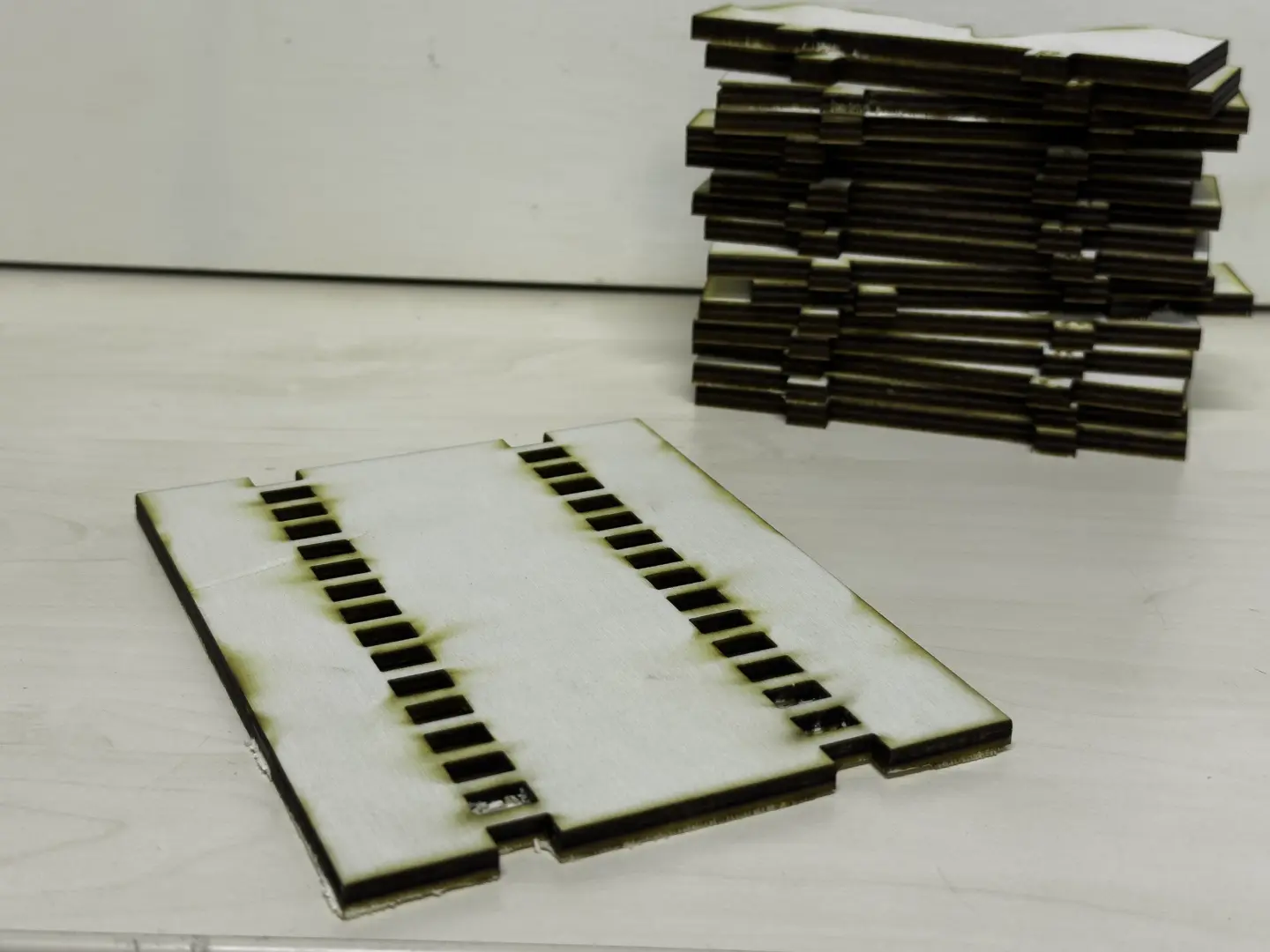
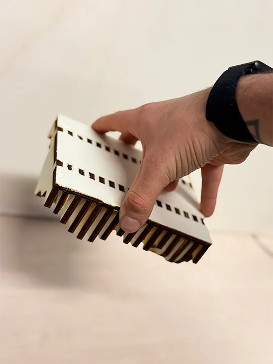
After the cut, everything is ready. Thanks to the labeling system (using letters), the pieces can be easily press-fit together.
Due to material constraints, I haven’t cut a larger object yet. However, I plan to buy a nice piece of wood soon and use it to create a new wall panel to decorate my office in our apartment.
The Houdini work file is available in the project files section. I think you can now see why I love Houdini so much—and maybe I’ll even convince some of you to give it a try. Let’s see if I’ll eventually hit the limits of Houdini during the Fab Academy and have to switch to SolidWorks.

To use the Wall Panel Creator, install my Operator Type Library (OTL) files via Assets > Install Asset Library in Houdini (Wall Panel Tool and SVG Coloring Tool).
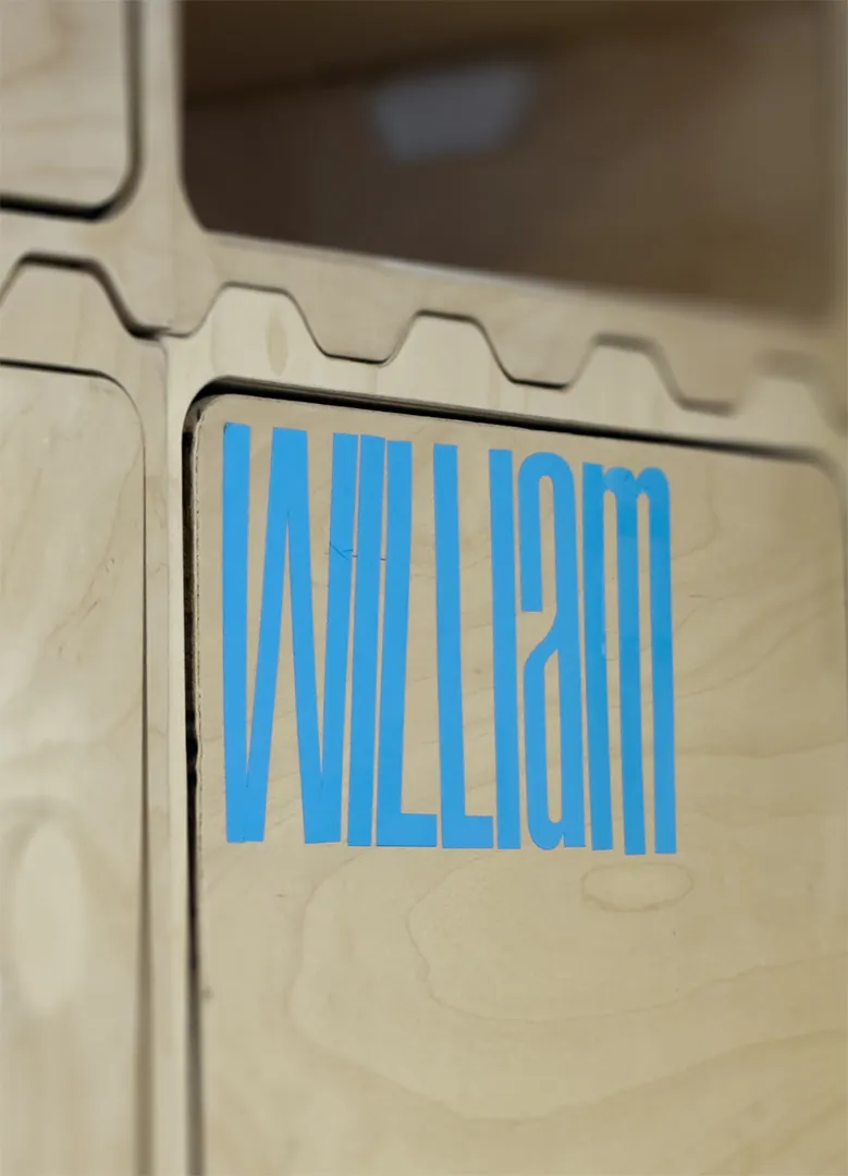
Vinyl Cutting
Vinyl Cutting
For vinyl cutting, I created a simple name tag. Since I need to store a lot of items during the Fab Academy in our laboratory, I thought it would be a smart idea to have a shelf dedicated to my things. To label it, I needed a name tag, and what could be better than a freshly vinyl-cut name tag?
The workflow is quite simple:
- Create a design you like, save it as an SVG file (although pixel-based designs are supported, they may cause issues during cutting), and then load it into the Cricut software.
- Next, position your design at the top corner and click Make It. From there, you can adjust the cut settings. There are several pre-made settings to choose from, and for standard vinyl, the Adhesive Vinyl setting works really well.
- You can also adjust the pressure at this stage. This is useful depending on your blade's condition—if it's new, you might need less pressure to get a clean cut, or if it’s getting dull, you can increase the pressure to ensure the blade cuts through the material properly.
- Once everything is set up, simply press the blinking button on the Cricut, and it will start cutting your design. Happy cutting!