This week I worked with five different inputs: a custom mutual capacitance proximity detector, a velostat pressure sensor, a KY-040 rotary encoder, the BNO085 IMU as an accelerometer for yaw sensing, and the BNO085 magnetometer as a magnetic rotary encoder. I didn't have a dedicated encoder IC like an AS5600 on hand, so I used the magnetometer directly with a small cube magnet.
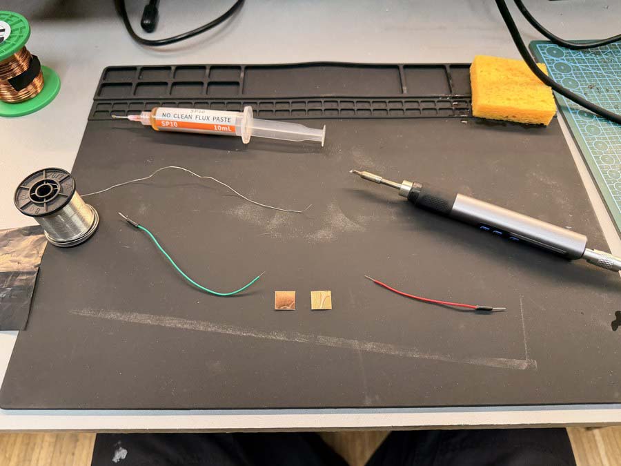
I wanted to make a sensor that could detect proximity, not just touch. Mutual capacitance works by transmitting a charge on one electrode and measuring how much coupling makes it across to the receiving electrode, a nearby hand disturbs that coupling in a measurable way.
My starting point was the Arduino Starter Kit's "Touch Sensor Lamp" example, which uses the CapacitiveSensor library on two pins. I shared it with Claude and asked about getting it running on the Barduino 4.0.2.
Download capacitive-sensor-library-example.ino
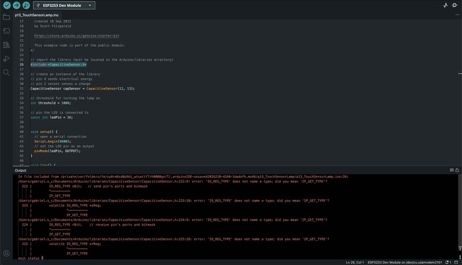
The CapacitiveSensor library only works on AVR boards, not the ESP32. I asked Claude:
"Yes but I'd like to try mutual capacitance using 2 pins. Ideally I want to sense proximity as well as direct touch. Or for it to work through plastic for example."
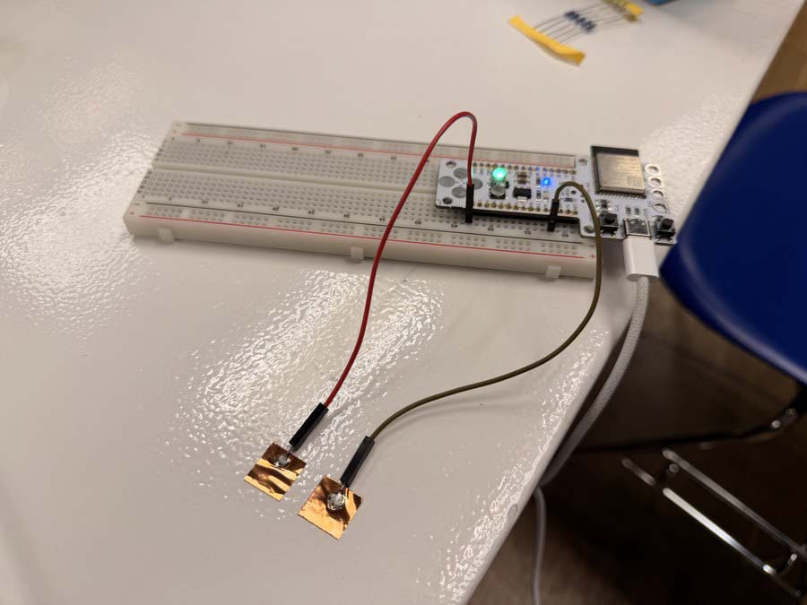
Claude wrote a charge-transfer sketch that drives a TX pad and times how long it takes the charge to couple across to an RX pad. This was the first version that actually ran, values sitting around 22 at rest and spiking to about 195 on direct pad touch.
Download mutual-cap-test-01.ino
I reported back: "Ok I used a 1M resistor and the reading seems to sit at around 21-22 when left alone. It goes to around 22-23 when I place my finger about 1 cm above the two copper pads. And it goes to 0 when I touch both. It shows 20000 and TOUCH when I touch the one connected to RX_PIN (13)". Claude switched to an analogRead approach with a brief charge window to simplify things. The readings came out completely inverted, the sensor was reading TOUCH at rest and dropping when I actually touched the pad.
Download mutual-cap-test-02.ino
I told Claude: "It's constantly reading 4000 something and saying TOUCH when untouched and it's reading 2000 something and saying PROXIMITY when I touch one of the pads. Nothing changes when my finger approaches though." To try to fix the inverted readings, Claude added a startup baseline calibration and more averaging. The delta values stayed at 0–2 regardless of where my hand was. analogRead just wasn't working.
Download mutual-cap-test-03.ino
After I said "Ok touch works when I touch the RX_PIN (13) but nothing happens when I approach the pads", Claude offered a few honest fallback options (built-in ESP32 touch hardware, bigger pads, or accepting touch-only). I pushed back: "No, I want to create a mutual capacitance sensor to place into a pomodoro timer watch I'm designing. I want this to work." Claude had me strip everything back to bare analogRead with no averaging to rule out any software artifacts. The output was completely flat at around 3750, zero response to hand proximity. The ESP32-S3 ADC is just too noisy for this.
Download mutual-cap-test-04.ino
I told Claude that nothing was changing no matter how close I got, but the very first version had shown some change, so something must have broken along the way. Claude went back to the charge-counting approach with a much lower timeout ceiling. I went back and got real proximity data, delta 1 at 9cm, delta 2 at 3cm, delta 3 at 1cm. The signal was there but weak.
Download mutual-cap-test-05.ino
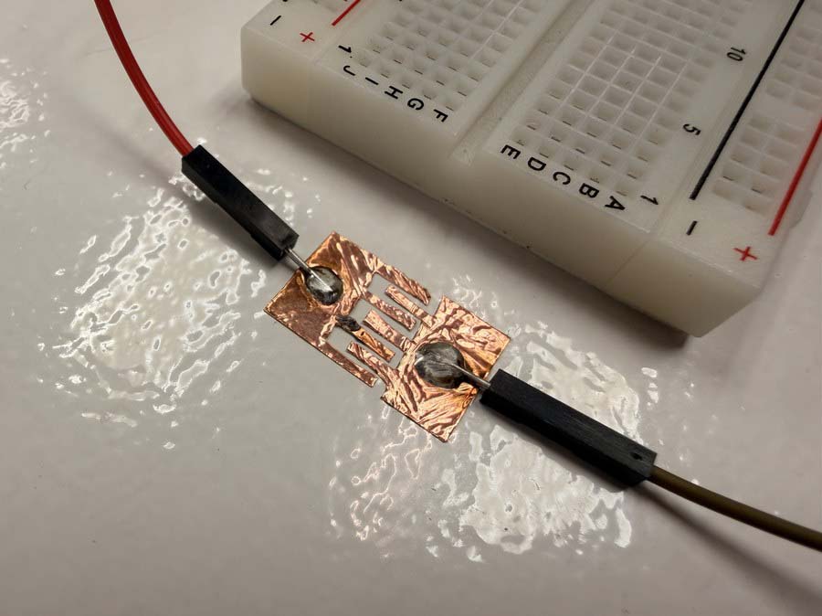
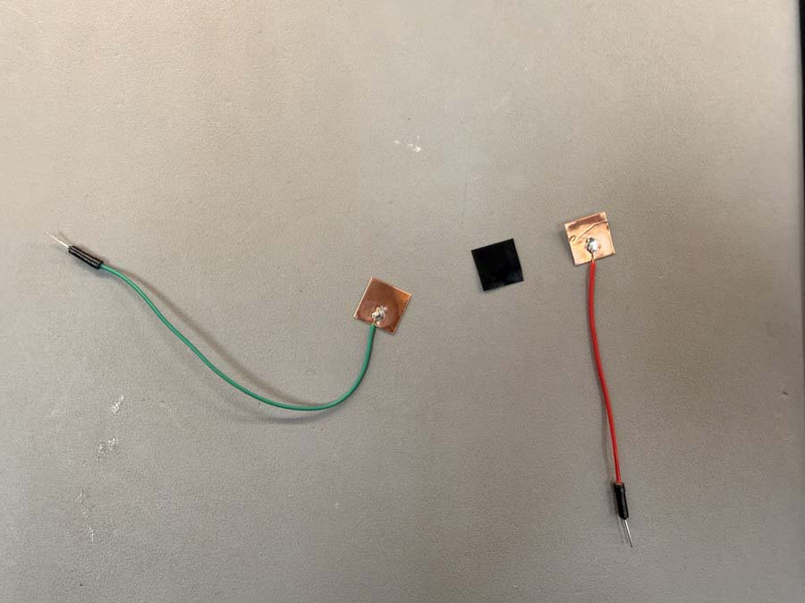
I reported the readings back to Claude, and it cranked SAMPLES up to 2000 to try to average out the noise, but the response barely moved. Claude pointed out that the pad geometry itself was the bottleneck, two small squares sitting side by side don't have enough shared edge to build up a meaningful signal. I mentioned the pads were about 12x12mm and 7mm apart, sized to fit inside my pomodoro watch, and Claude suggested switching to an interdigitated comb pattern to massively increase the shared edge between TX and RX.
Download mutual-cap-test-06.ino
This demo was still running mutual-cap-test-06.ino, with the original simple side-by-side copper pads, just before I switched over to interdigitated pads.
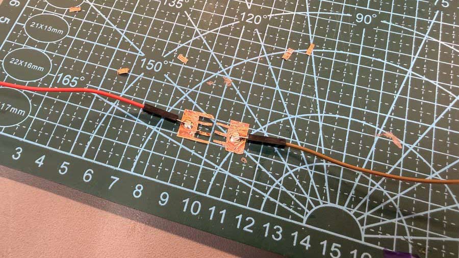
At this point I cut an interdigitated electrode pattern with a utility knife. The comb geometry puts much more shared edge between the TX and RX pads, which dramatically increases the coupling area.
I found this fanatastic document on capactive touch sensor design: Capacitive Touch Sensor Design Guide
This next recording is from the same mutual-cap-test-06.ino code (linked above), now running with the new interdigitated pads.
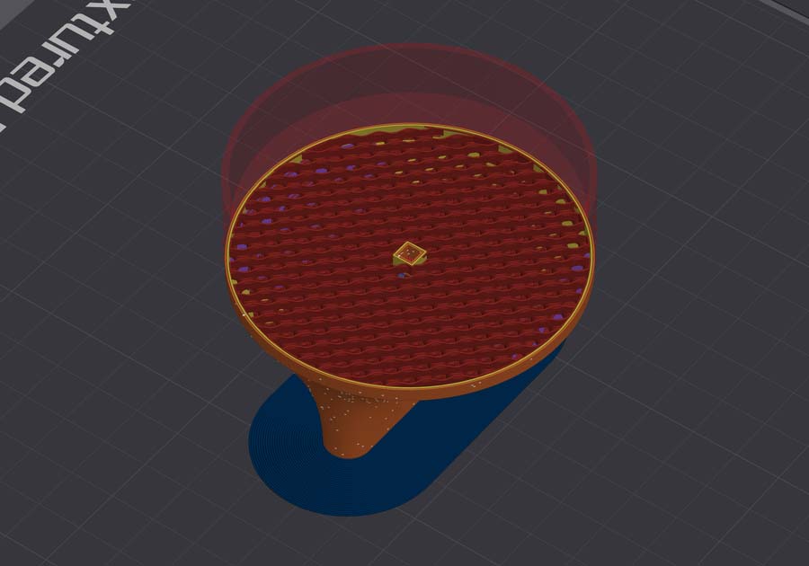
I also tested the sensor through a piece of 2mm thick PLA from a test print that was laying around and it was able to detect proximity as well as touch, still running the same mutual-cap-test-06.ino code.
I then made my own pressure sensor from copper tape and velostat, a carbon-black film that gets more conductive when you compress it. The plan was to eventually replace the tactile button for my custom pomodoro timer watch board. I wired it as a voltage divider with a 3.3K resistor and connected it to GPIO 12 on the Barduino.
The pressure sensor readout worked well in the serial monitor, from 0-4095 depending on how much force I used.
Download velostat-pressure-sensor-test-01.ino
I then mapped the pressure input reading to control the brightness of the NeoPixel on the Barduino.
Download velostat-pressure-sensor-test-02-LED.ino
The KY-040 was straightforward to wire up, CLK on GPIO 13, DT on GPIO 14, SW on GPIO 15, but had a lot of bounce. I fixed that with the ESP32Encoder library. Once it was reading cleanly I mapped the position to NeoPixel brightness, then to colour temperature.
Download rotary-encoder-test-02.ino
Download rotary-encoder-LED-dim.ino
Download rotary-encoder-LED-colourTemp.ino
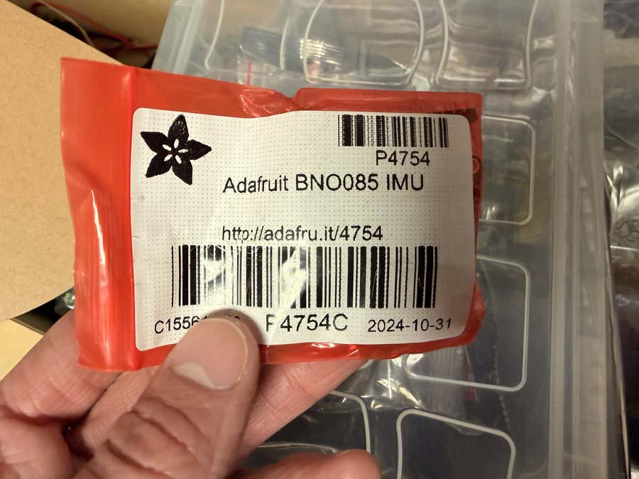
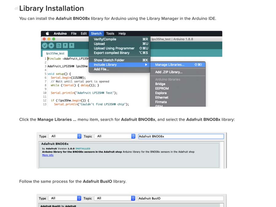
I wanted to explore using the BNO085 as a more interesting input. It's a 9-DOF IMU with an accelerometer, gyroscope, and magnetometer all in one. I asked Claude:
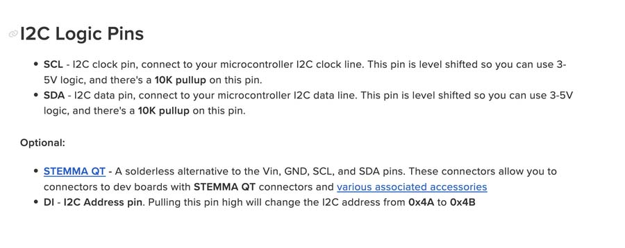
"I'd like to play around with an accelerometer, specifically the Adafruit BNO085 board. I don't have a dedicated magnetic encoder like the AS5600 on hand, so I'd like to use the BNO085 as if it were a rotary encoder, having it rotate on a knob to tell the position of the knob. I'm using my XIAO ESP32-S3 Sense board connected via STEMMA QT."
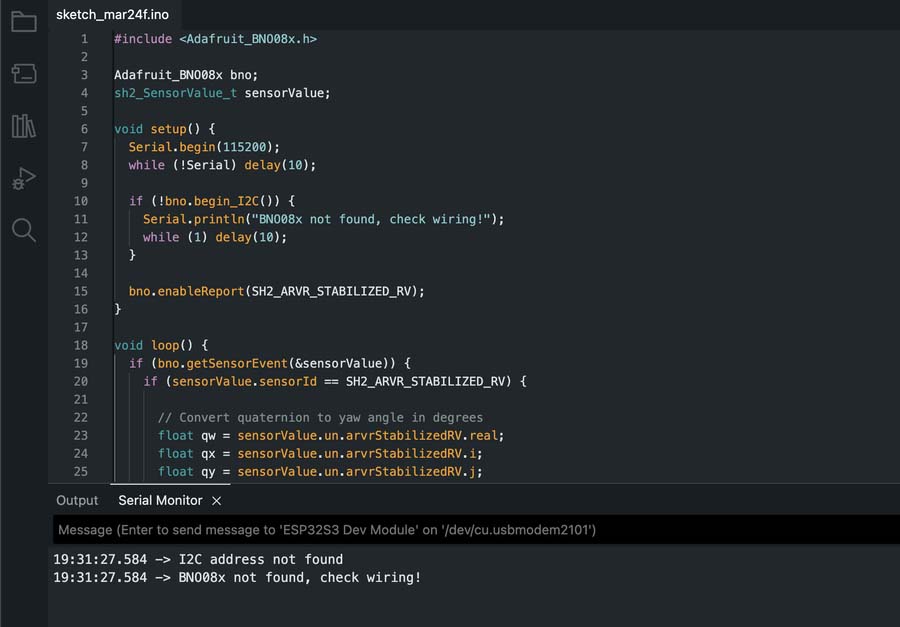
Claude suggested starting with reading orientation as a stand-in rotary encoder, since it would be faster to get working than the magnetometer approach, and we could try that second.
cpp#include
void setup() {
Serial.begin(115200);
while (!Serial) delay(10);
Wire.begin();
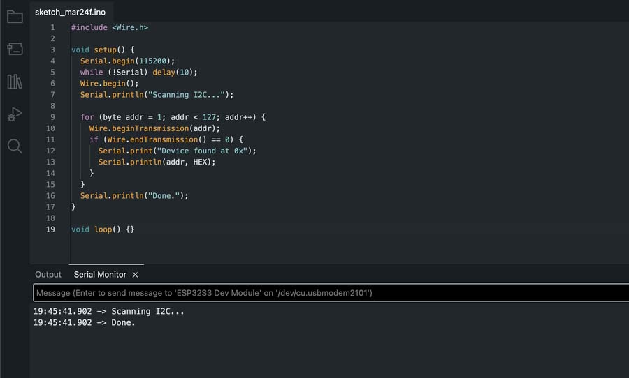
Serial.println("Scanning I2C...");
for (byte addr = 1; addr < 127; addr++) {
Wire.beginTransmission(addr);
if (Wire.endTransmission() == 0) {
Serial.print("Device found at 0x");
Serial.println(addr, HEX);
}
}
Serial.println("Done.");
}
void loop() {}
#include
void setup() {
Serial.begin(115200);
while (!Serial) delay(10);
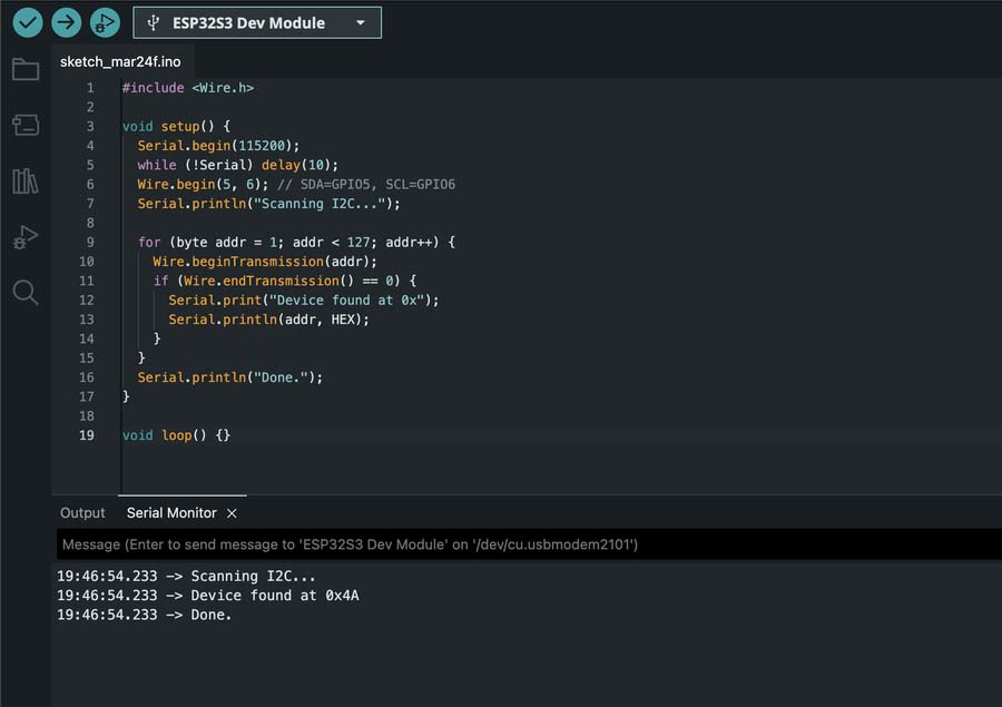
Wire.begin(5, 6); // SDA=GPIO5, SCL=GPIO6
Serial.println("Scanning I2C...");
for (byte addr = 1; addr < 127; addr++) {
Wire.beginTransmission(addr);
if (Wire.endTransmission() == 0) {
Serial.print("Device found at 0x");
Serial.println(addr, HEX);
}
}
Serial.println("Done.");
}
void loop() {}
The yaw data readout was very precise and quite stable.
Download BNO085-accel-test-01.ino
Since I didn't have an AS5600 or similar dedicated magnetic encoder IC on hand, I asked Claude:
"I want to try using the BNO085's magnetometer as an encoder. Please tell me how I should proceed and which chip on the board is responsible for it."
Claude explained the magnetometer is built into the BNO085 itself, not a separate chip, and that holding a diametrically magnetized magnet above it and computing atan2(y, x) on the X/Y readings gives an absolute angle, the same principle dedicated chips like the AS5600 use in hardware. After a couple of compile errors, the correct constant turned out to be SH2_MAGNETIC_FIELD_CALIBRATED, not SH2_MAGNETIC_FIELD, I had a working raw output.
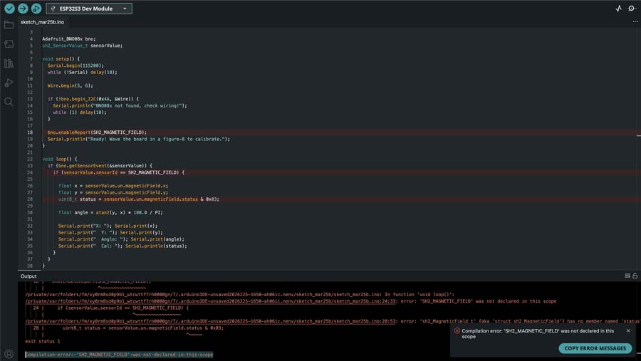
Download BNO085-magneto-test-01.ino
Getting the readings into the Serial Plotter took one more fix, comma-separated Label:value pairs instead of plain text, since that's the format the plotter expects.
Download BNO085-magneto-test-02.ino
The angle was working but quite jittery. Claude suggested a few fixes and recommended starting with a simple rolling average since I was already set up for it, so I asked it to add that.
Download BNO085-magneto-test-03-smooth.ino
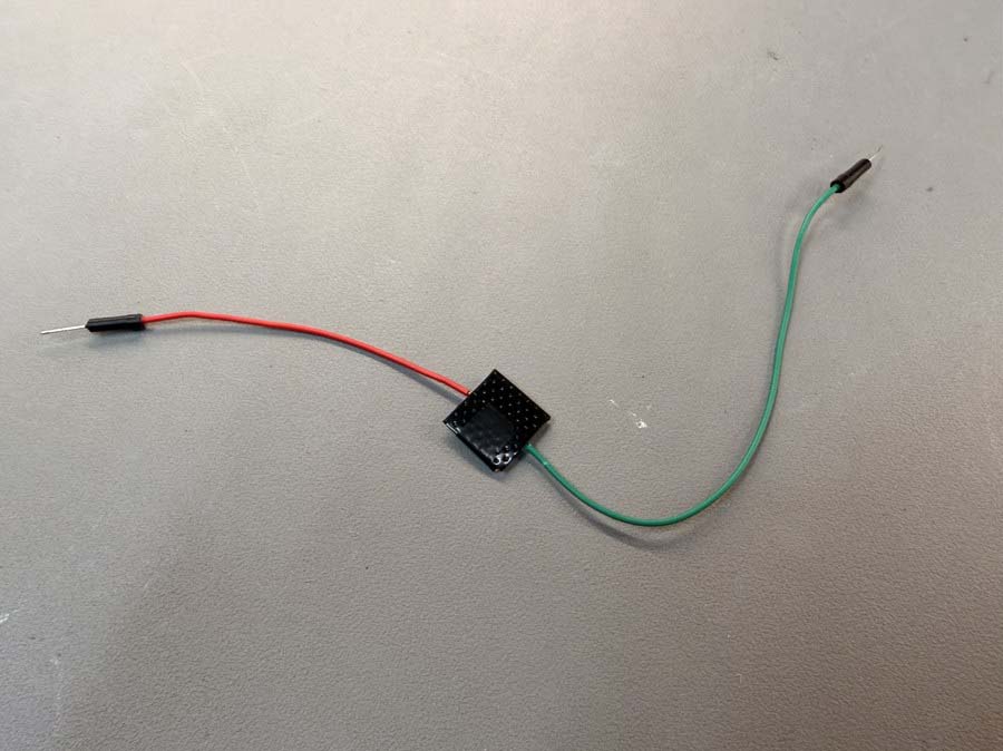
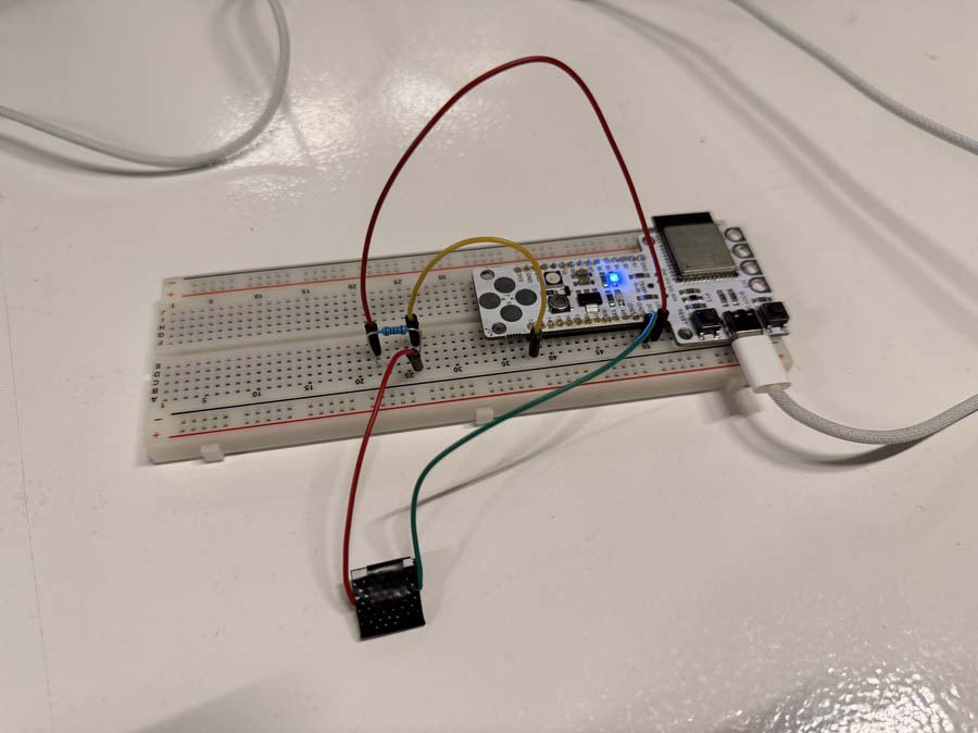
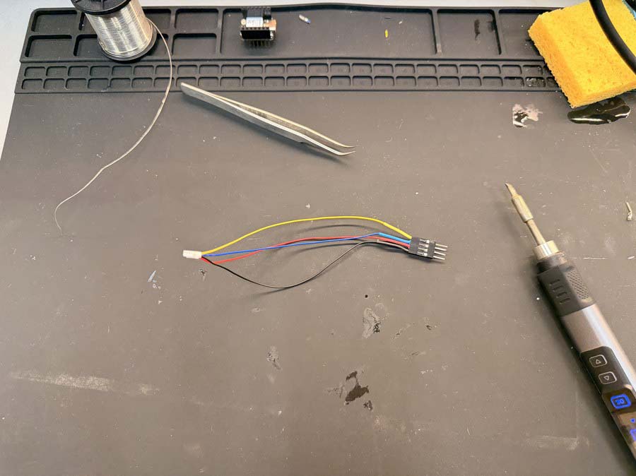
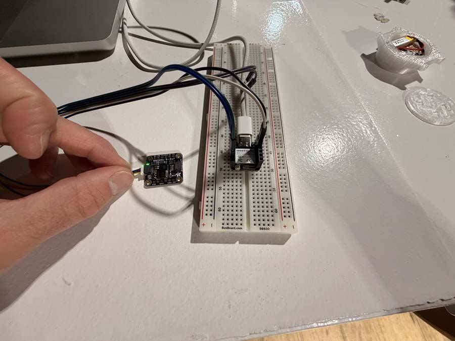
I threw together a quick proof of concept from parts I had lying around to validate the BNO085 + rotating magnet approach. I also tried soldering wires directly to a NeoPixel to use as an output indicator, but held the iron on it for too long and fried it.
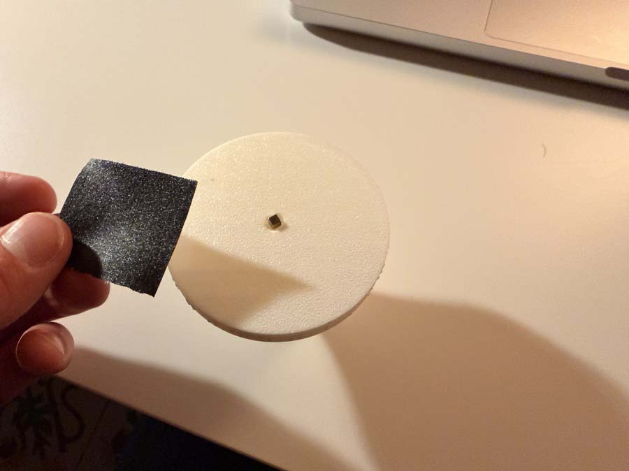
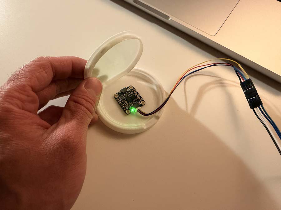
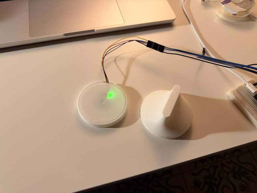
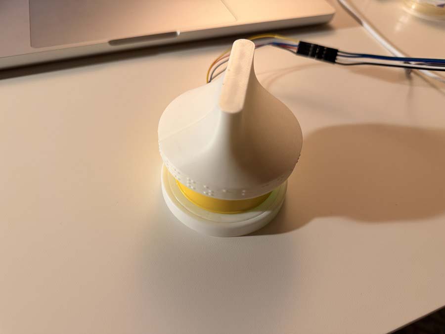
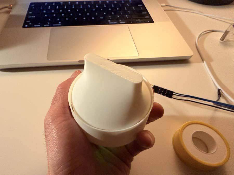
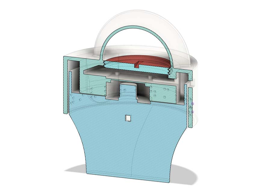
I decided to modify my week 02 braille learning device to accomodate the BNO085 and a magnet to be able to read the position of the knob. The magnet would be embedded in the knob print. I created a pocket for affixing the BNO085 with a threaded hatch for access to the board and a hole for the wires to go to my XIAO. This was only a concept that would be used for testing purposes as I continue to iterate on this design.
On one of my boards I used a tactile-switch as input to change between various states of my alarm clock and pomodoro timer.
idle state: toggles alarm on or offpomodoro running state: pauses the pomodoro timerpomodoro paused state: resumes the pomodoro timerpomodoro active state: resets to idle
        Button behaviour (meaning depends on current state):
          Short press
            idle              show alarm time for 3s
            pomodoro running   pause
            pomodoro paused     resume
            alarm firing       dismiss (also turns alarm off)
          Hold 2s
            pomodoro active (any)   reset to idle
            idle                    toggle alarm on/off
The button is wired with an external 10kΩ pull-up resistor between the signal line and 3.3V. Without it, the pin floats when the button is open. It's not connected to anything, so it picks up electrical noise and randomly reads HIGH or LOW. The pull-up holds the pin firmly at 3.3V at rest. When you press the button it shorts the line to GND, giving a clean LOW. The firmware uses pinMode(BUTTON_PIN, INPUT) rather than INPUT_PULLUP because the resistor is on the PCB itself, not relying on the weaker internal one.
The button is on GPIO44, and the firmware distinguishes short and long presses. A press is confirmed only if the same state is still present 20ms later. This is the debounce window that filters out the mechanical chatter of the switch contacts. If the pin has been LOW for 2000ms without releasing, a hold is fired. If it releases before that threshold, it counts as a short press.
#define BUTTON_PIN     44
#define BTN_DEBOUNCE   20      // ms
#define BTN_HOLD_MS  2000      // ms

void handleButton() {
  bool raw = digitalRead(BUTTON_PIN);
  if (raw == btnLastRaw) return;
  delay(BTN_DEBOUNCE);
  raw = digitalRead(BUTTON_PIN);
  if (raw == btnLastRaw) return;
  btnLastRaw = raw;

  if (raw == LOW) {            // press started
    btnDown      = true;
    btnDownAt    = millis();
    btnHoldFired = false;
  } else {                     // release
    if (btnDown && !btnHoldFired) onShortPress();
    btnDown = false;
  }
}

void checkHold() {
  if (btnDown && !btnHoldFired && millis() - btnDownAt >= BTN_HOLD_MS) {
    btnHoldFired = true;
    onHoldPress();
  }
}