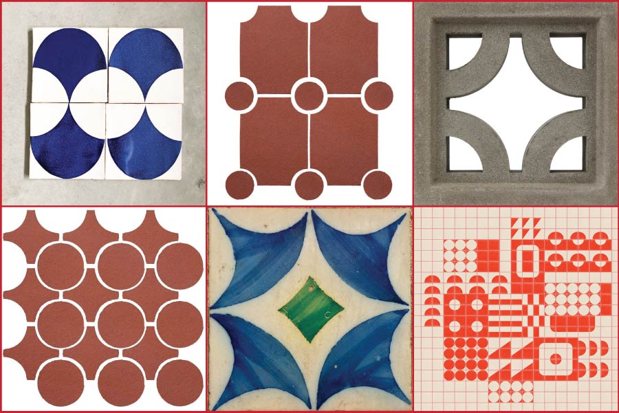
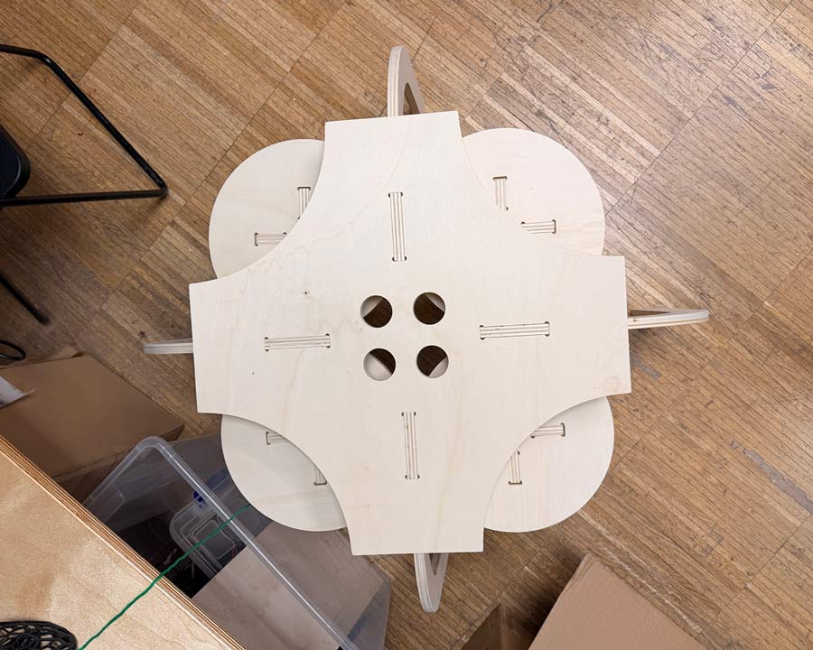
My design explorations were informed by tile geometries. The goal was to maximize material use and minimize waste.
I wanted:
For this assignment, we were each provided a 1.22 m x 2.44 m piece of pine plywood with a 15mm thickness. For this reason, I wanted to create a square tile so that I would only use half of the workpiece. That way, if needed, two sets could be made out of my single board. Or I could simply use the other half for something else.
The process of trying to find a geometric layout that outputs functional pieces for a 3D set of objects was a really fun puzzle to solve.
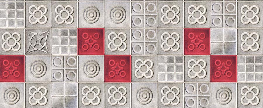
While walking in Barcelona one day, I noticed a specific panot (tile) that caught my eye and made me think of a nesting opportunity.
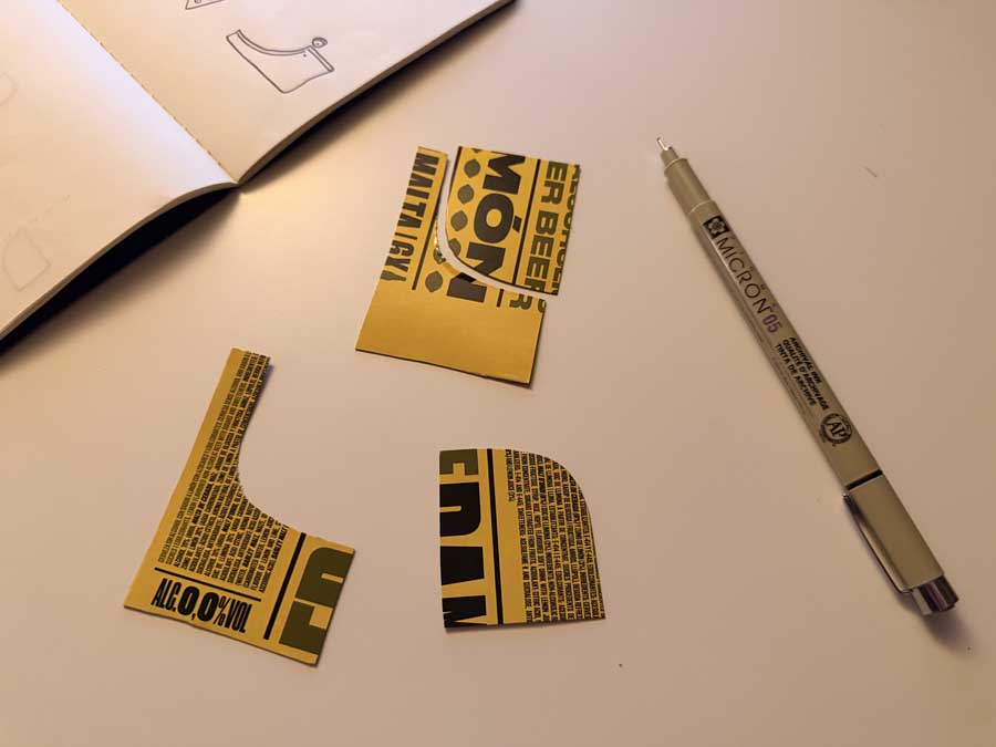
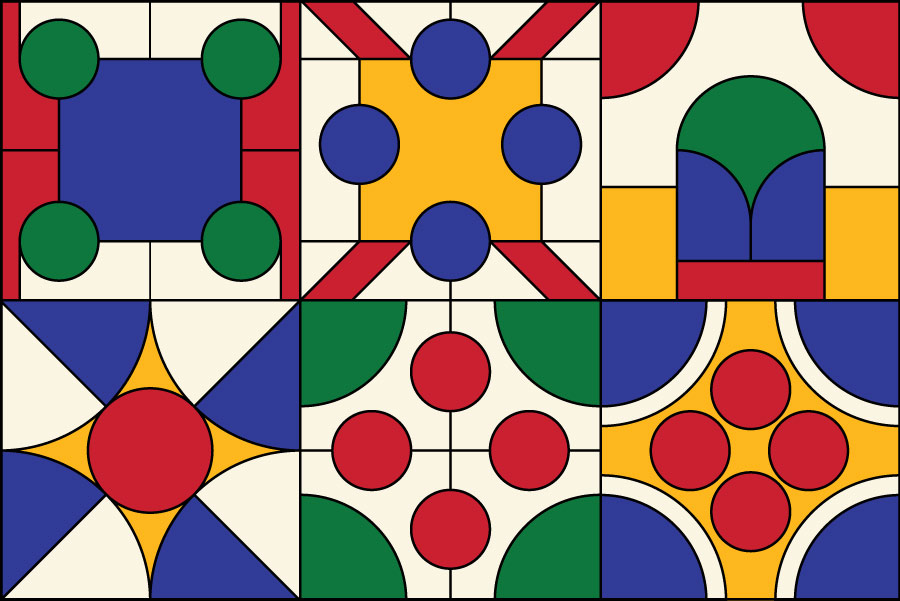
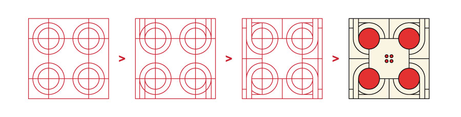
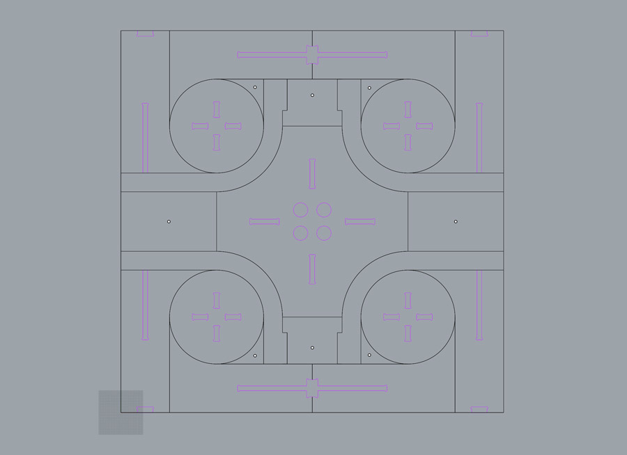
I used a grid and an iterative approach to develop the layout in Illustrator.
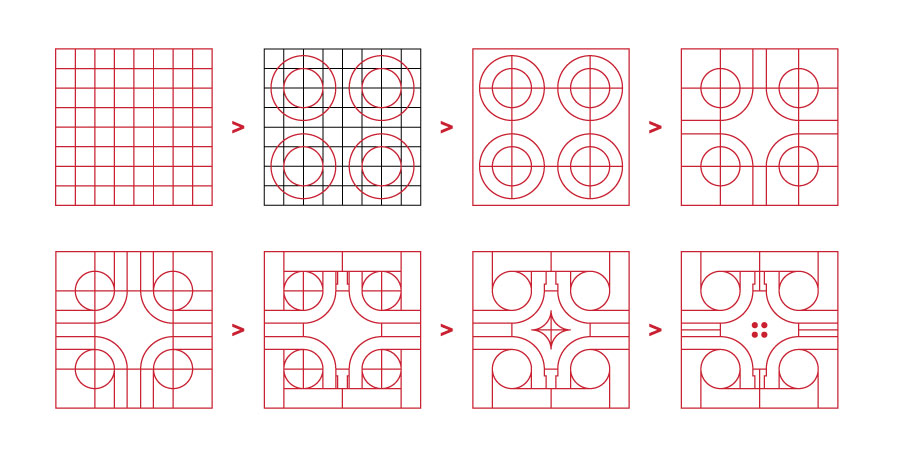
I also explored other similar layout alternatives.
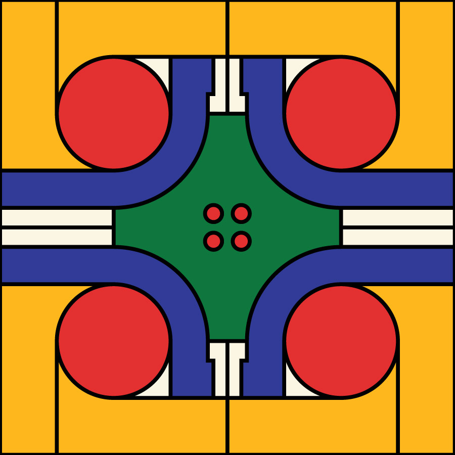
The final designed tile from Illustrator
I created a fully parametric sketch of my tile design using Fusion, based on the exact layout I had developped in Illustrator.
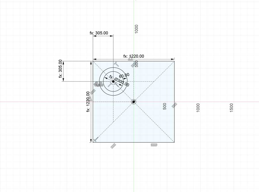
A lot of constraints...
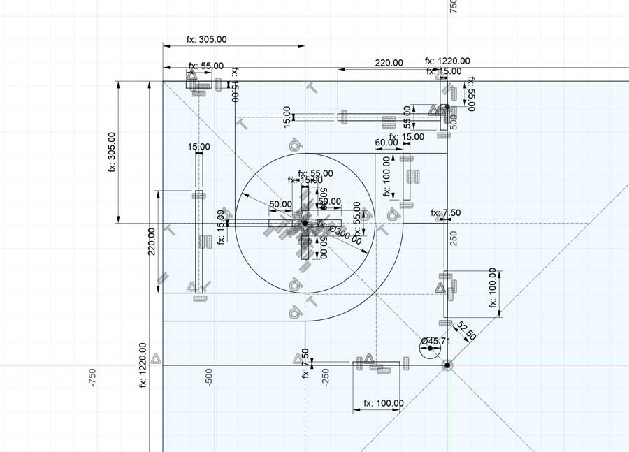
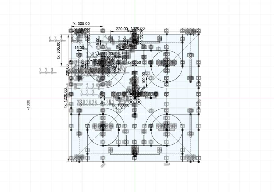
I designed one corner and mirrored the sketch components to all four corners.
The final constrained sketch.
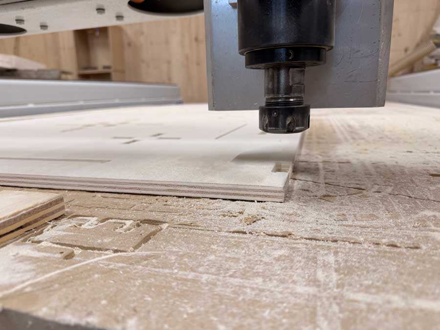
I extruded the sketch to 15 mm, which was the thickness of the plywood we were provided for the week.
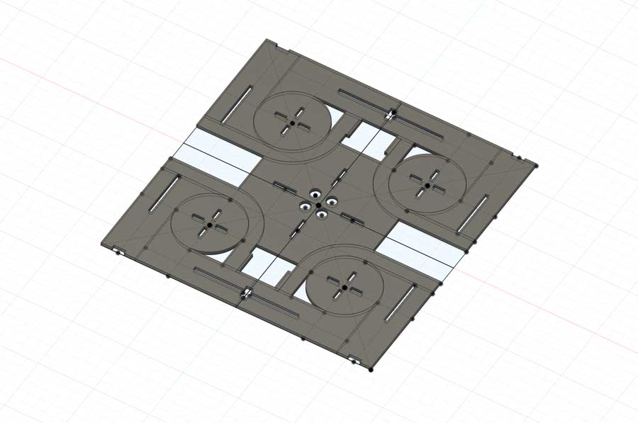
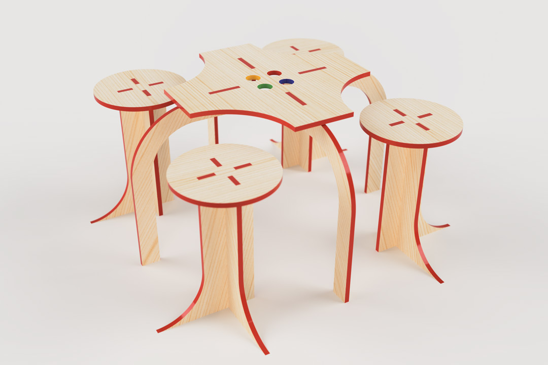
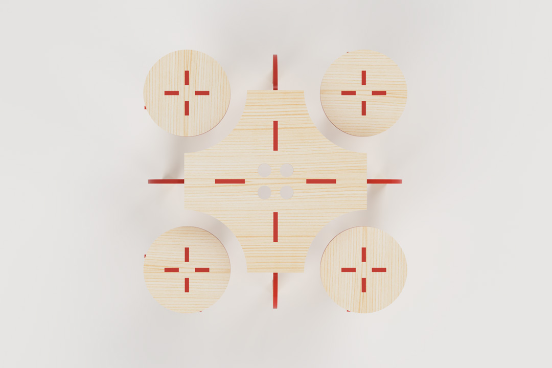
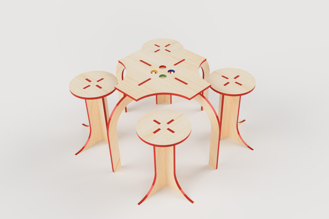
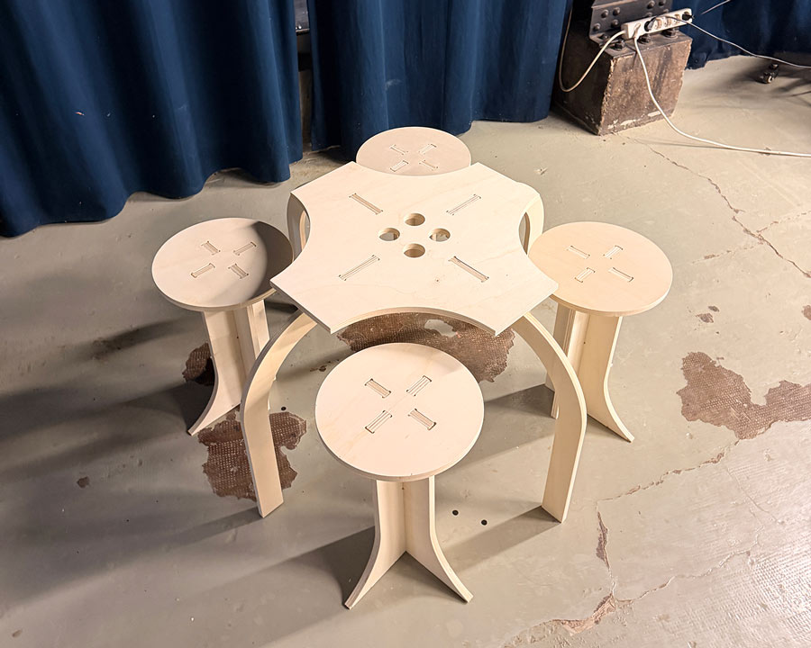
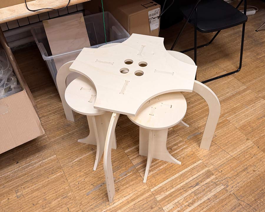
I used those parts to create a quick mock-up model of what the assembled pieces would look like.
The main points:
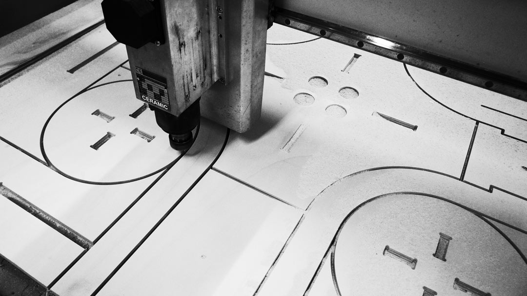
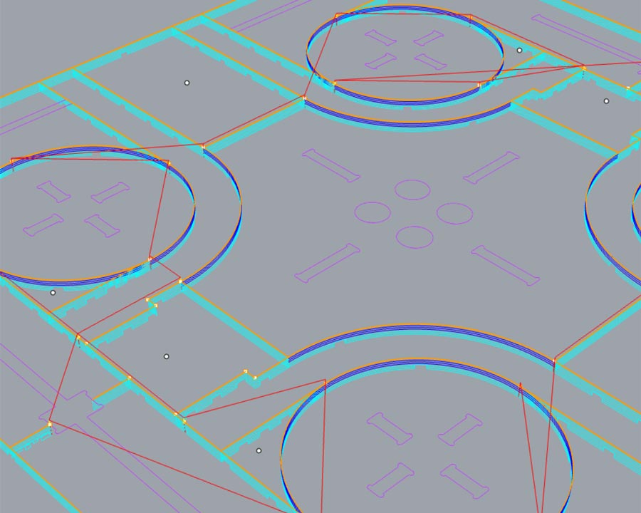
Since our end mill bit was 6mm in diameter, I started by setting kerf offset lines in Rhino to adjust all the joint dimensions.
For the engraving layer, I set an offset line to 3mm on either side of the centre of the toolpath.
For the pocketing layer, I set an offset line to 3mm towards the inside of the pocketing toolpath.
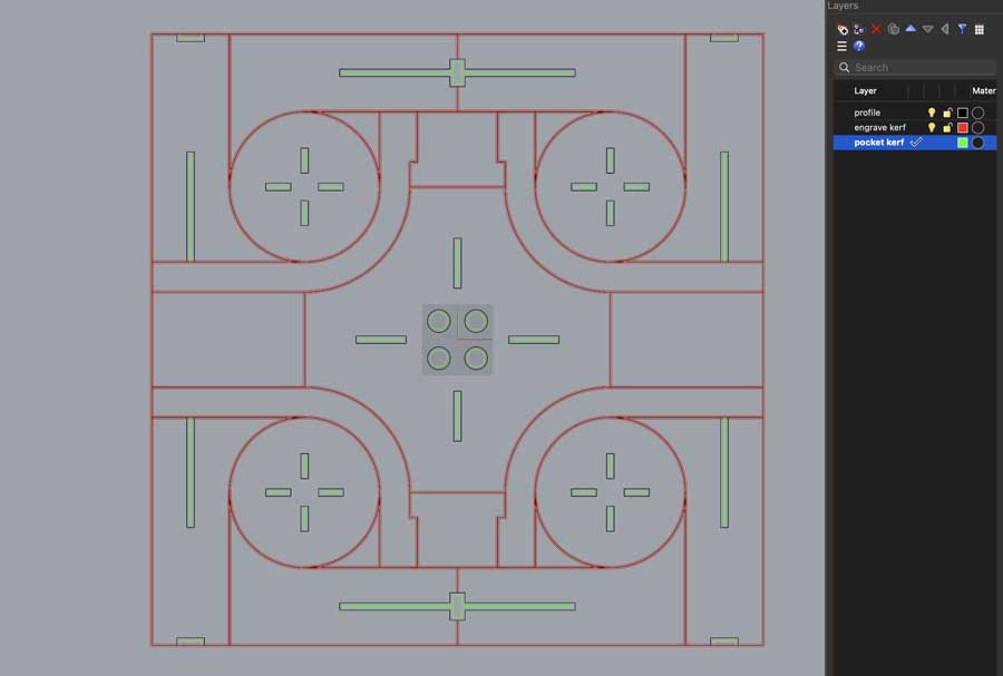
Due to my edge-to-edge layout, I had to find small unused pieces within my design to add screw locations in order to secure the piece to the bed. I also added an abundant amount of bridges to make sure that all pieces were always interconnected.
I then manually added dogbones to the corners of all of my pocketing operation areas, in order to avoid having rounded edges that would prevent pieces from joining together properly.
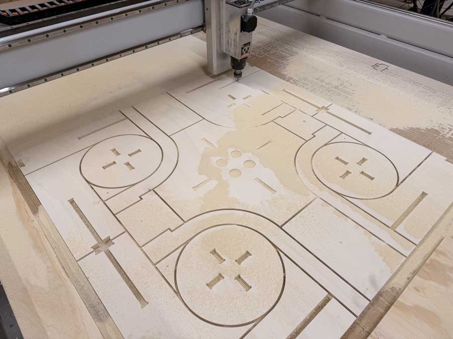
With engraving, pocketing, and drilling operations set to separate layers in Rhino, I was ready to run the Rhino CAM simulation to see how the tool would move across the piece.
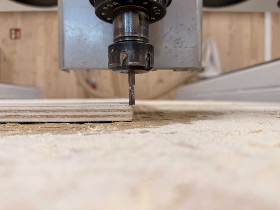
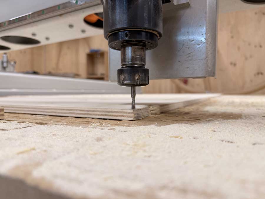
The settings below are what I ended up running on the Raptor CNC machine with the 6mm flat end mill.
Use most of the same settings as above, however: set the total cut depth to 3mm and select a 12mm end mill size. Even though we were cutting with a 6mm bit, the tool size set for these screw hole points should be 12mm, since it's just marking a dot. The larger size gives clearance for surrounding geometry. Always double check that it doesn't end up touching the workpiece or another toolpath before running it.
I carefully positioned the end mill to find the exact XYZ zero point on the corner of my workpiece.
I then ran the operations in this order:
When I re-exported the NC files from Rhino CAM, I must have accidentally selected the screw holes which were also set to an engraving operation. When I pressed play for the engraving operation, the machine suddenly decided to destroy itself.
The bit was nowhere and everywhere at the same time.
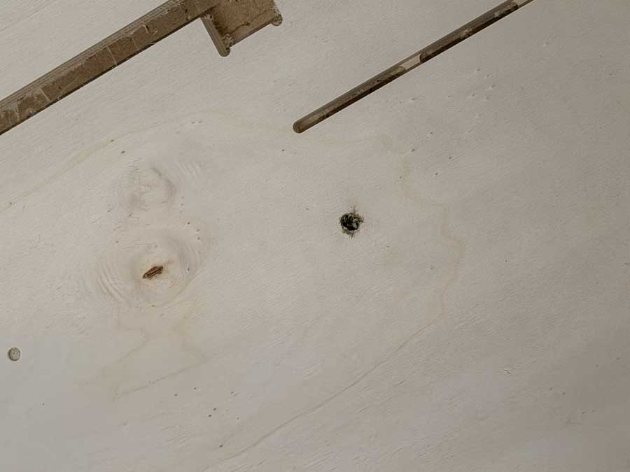
The rest of the operation went well after that mishap.
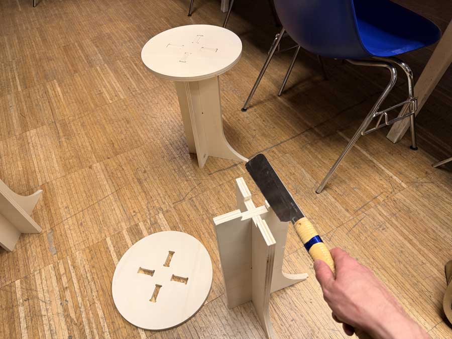
Once all the operations were complete, I could remove the screws and chisel away at the bridges to seperate the workpiece.
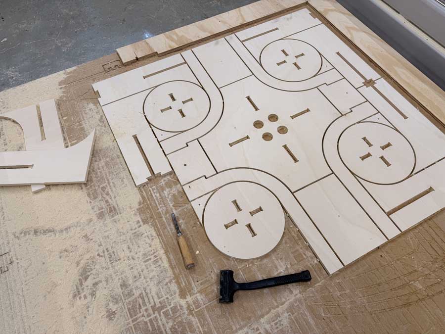
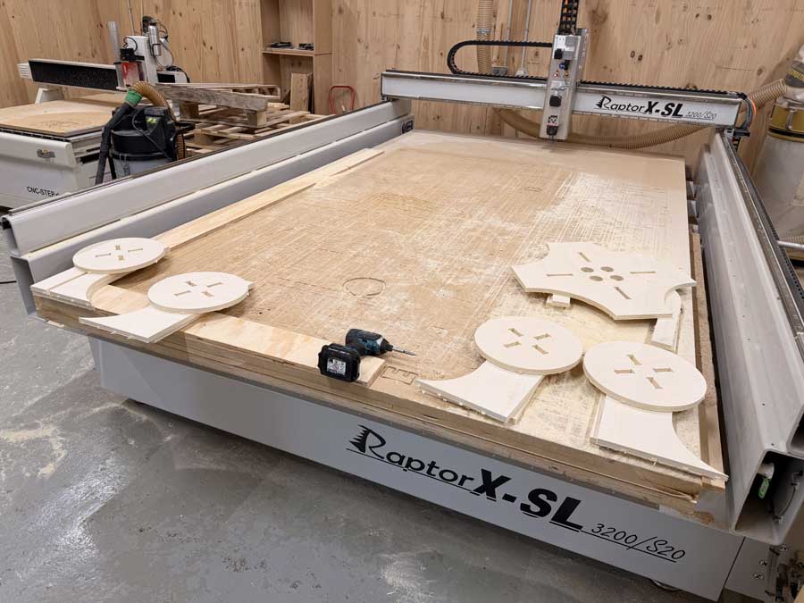
I first started by using a router to remove the bridges from the edges of each piece.
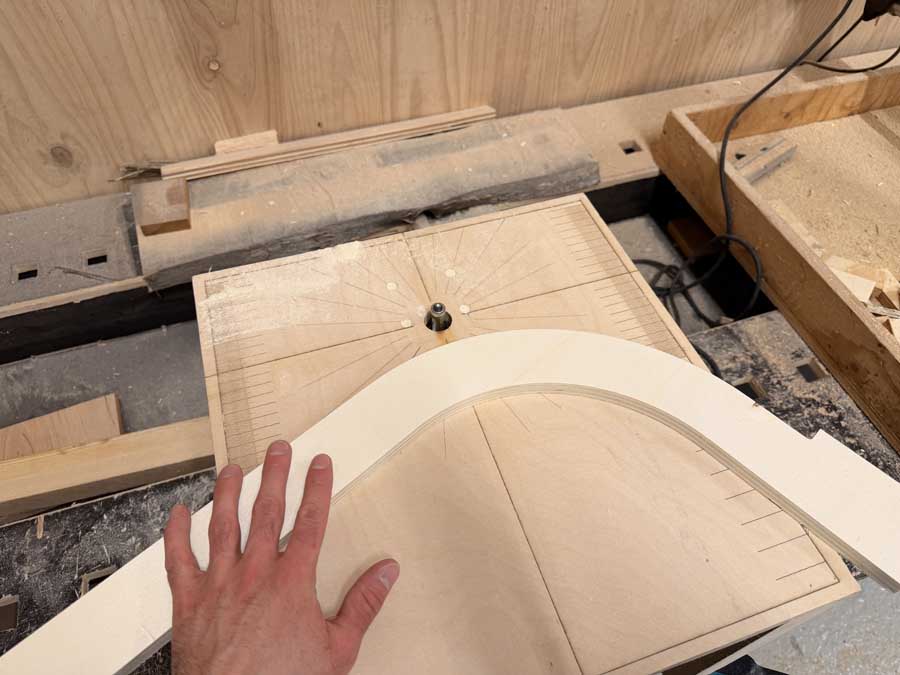
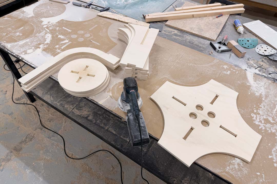
I then sanded the faces of each piece with an orbital sander and did the edges by hnd.
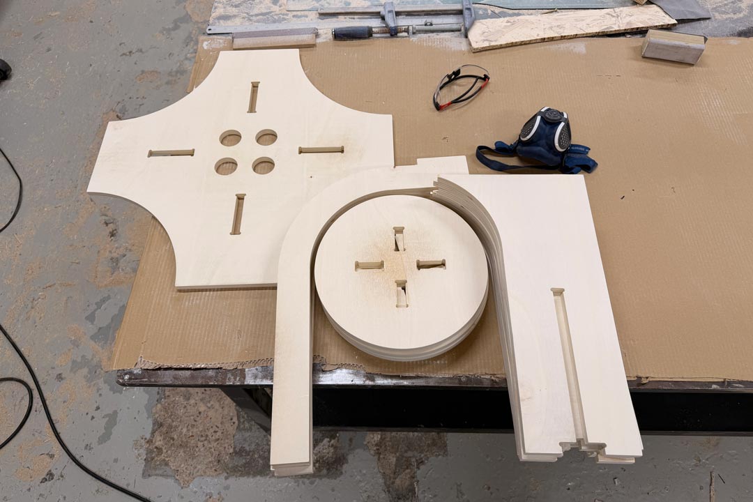
I discovered that I made a mistake on one half of the tool stands when I adjusted for kerf. I needed to cut 3mm off some of the joints with a hand saw.