 gabriel stacey-chartrand
gabriel stacey-chartrand
gabriel stacey-chartrand
This week we were introduced (or reintroduced) to working with CAD software in both 2D and 3D. I started using Google SketchUp in high school for personal projects. I then used Rhino throughout my architecture studies, along with AutoCAD and Vectorworks (unfortunately). In recent years, I've moved over to Fusion for personal projects and occasional 3D printing. In the 2D space, I use Illustrator for my graphic design work and have never used anything else (and likely won't).
I wanted to use this opportunity to continue exploring my final project's conceptual direction. I continued investigating themes of ADHD, smoking addiction, and differences in time perception, which will inform my final project.
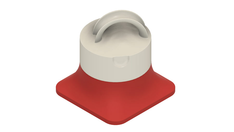
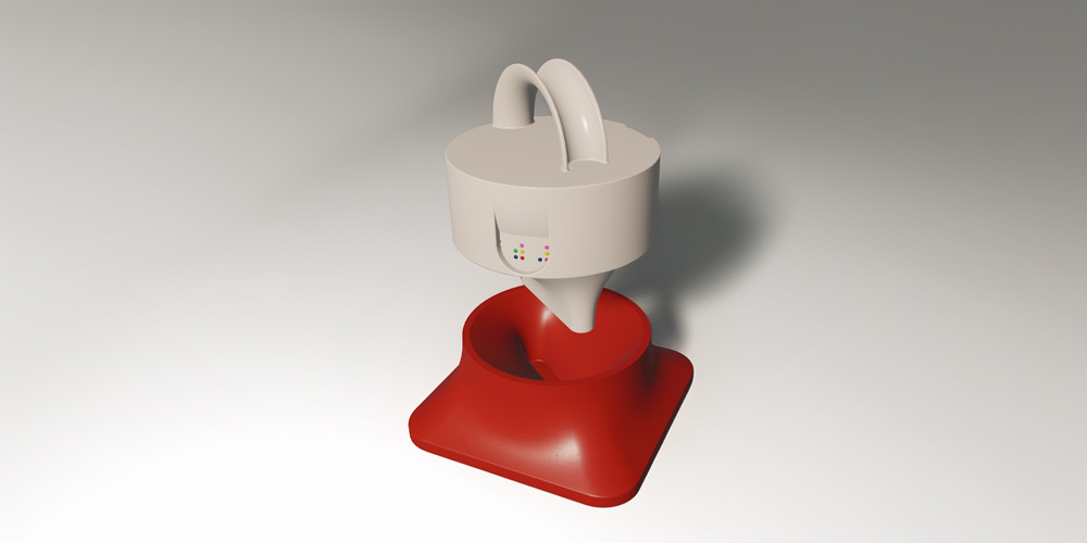
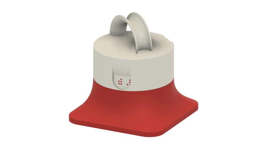
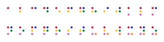
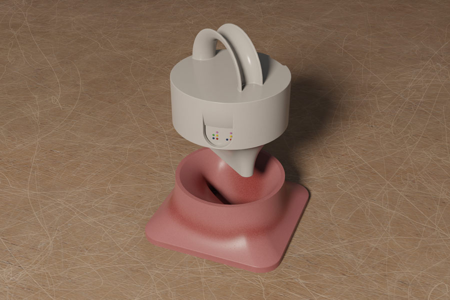
For this design exercise, I decided to create a braille kitchen “timer”. However, to reinforce the idea of avoiding precise time in my final project, I used the braille alphabet on the dial instead of braille numbers. The goal was to design a relative-time object that communicates a finite experience without relying on numbers.
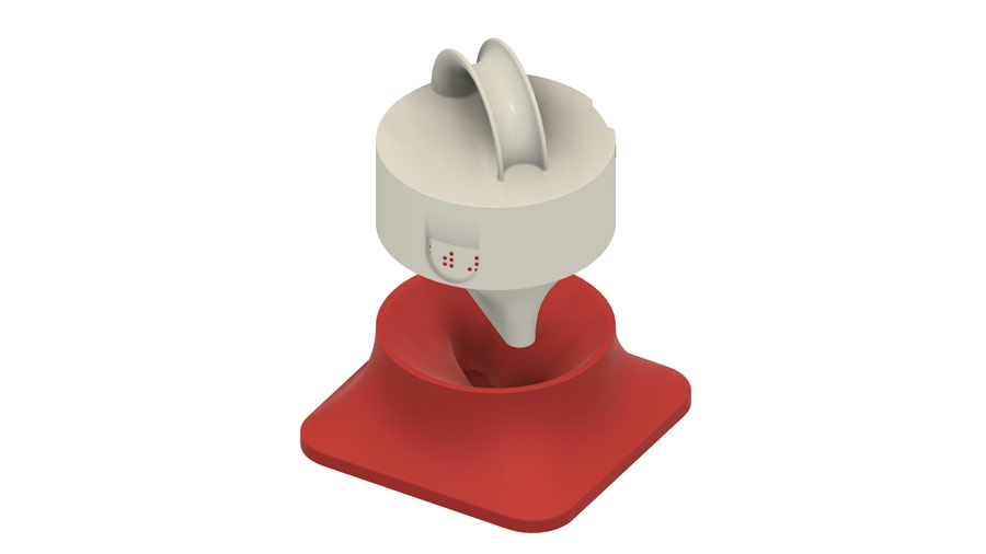
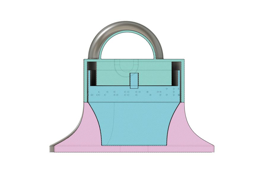
The base is inspired by vintage ashtray designs. The diameter of the timer body is informed by the dimensions of a tin of nicotine pouches. It's the perfect size for comfortably wrapping your fingers around the edges. Any larger or smaller would feel uncomfortable.
The handle is inspired by coffee mugs and the Alessi 9090 Moka Pot.
The dial used to start the timer is large, but gentle, with a palm-fitting shape. It invites you to turn it and feels comfortable in the hand.
(A mirrored version of the braille “timer” could be created for left-handed users.)
Dangerous time sink.
I started in 2D. Illustrator was the obvious choice since I've been using Adobe products my whole life. I wanted to lay out the full braille alphabet and define the colour palette, expanding it from the four dots in my logo.
I opened my logo file in a new Illustrator document and resized its circles to exactly 1.44 mm using the Transform panel (W and H fields), then repositioned them so each dot was exactly 2.340 mm centre-to-centre (both values taken directly from the NLS Specification 800 braille standard). I moved two dots down to form the 2-column x 3-row grid of a braille cell, then used the Color Picker to select two new colours for those dots that would complement the existing colours from my logo. I grouped the full cell with Cmd+G, then duplicated it by holding Option+Shift and dragging it to a guide I had set at exactly 6.2 mm (the standard centre-to-centre spacing between adjacent cells). I repeated the duplication 24 more times using Cmd+D (Transform Again), which re-applies the last move precisely, giving me all 26 cells without any manual nudging. Then I went through each cell and deleted the appropriate dots to spell out the full braille alphabet.
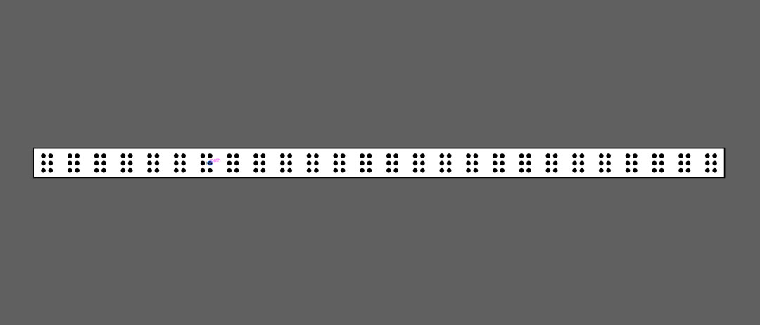
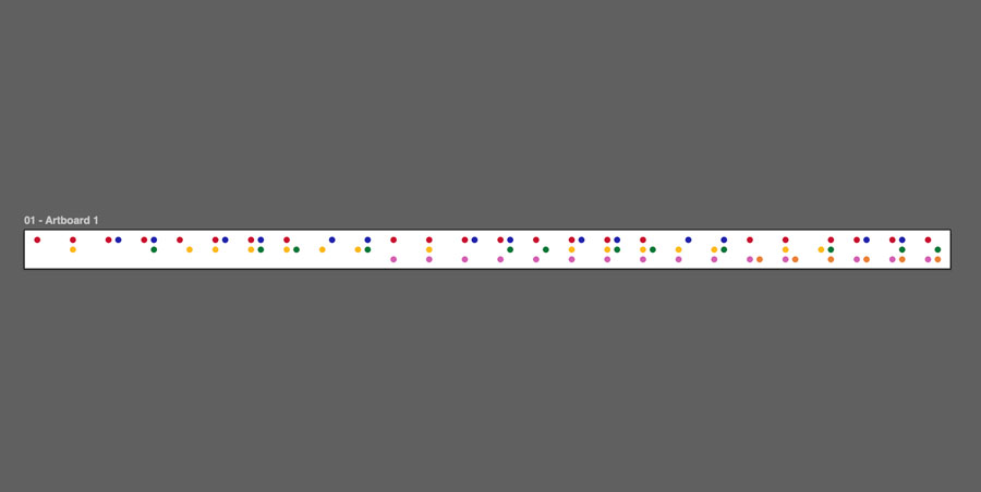
Scaling the braille dots correctly was trickier than expected. Each dot has a specific diameter and spacing relative to the cell size. I fixed it by calculating the correct ratio and constraining the geometry from there. The dots are also filleted because real embossed braille isn't sharp.
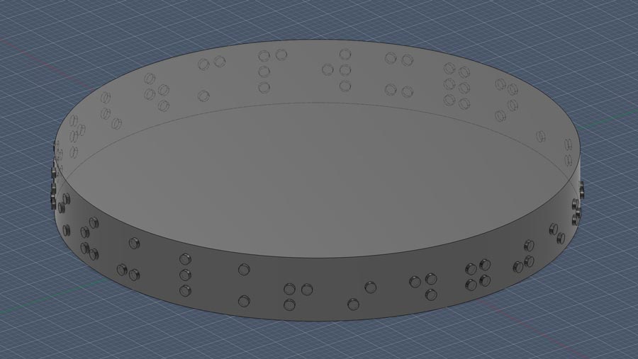
Getting the braille to live on the wheel as a separate set of objects, attached to the cylinder but not merged into it, took some iteration. I needed the geometry to stay independent so the assembly could be driven correctly.
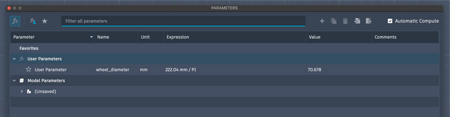
Embossing the braille into the wheel
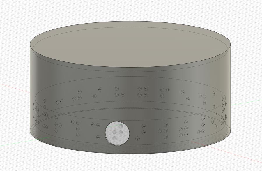
Using loft for the dial knob
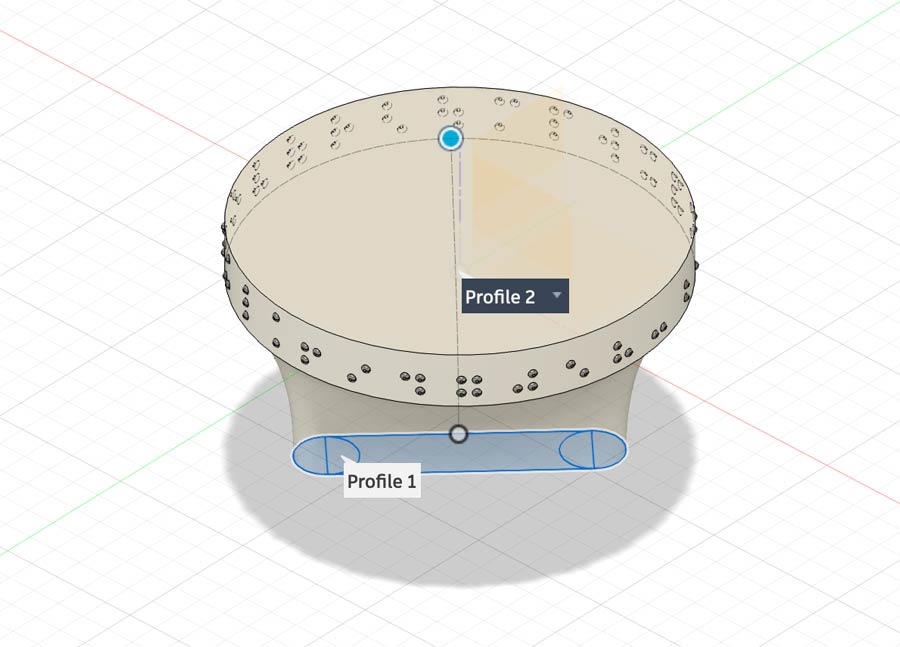
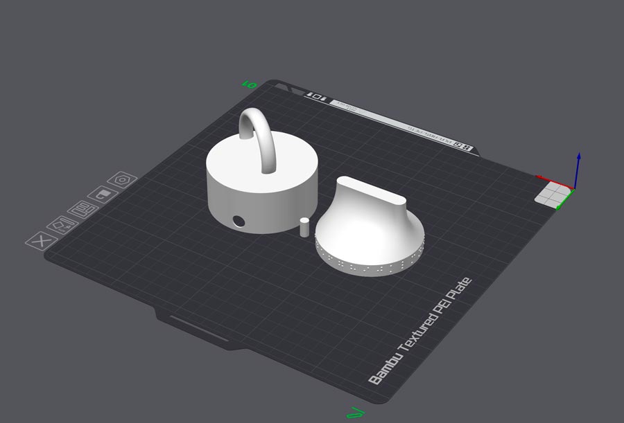
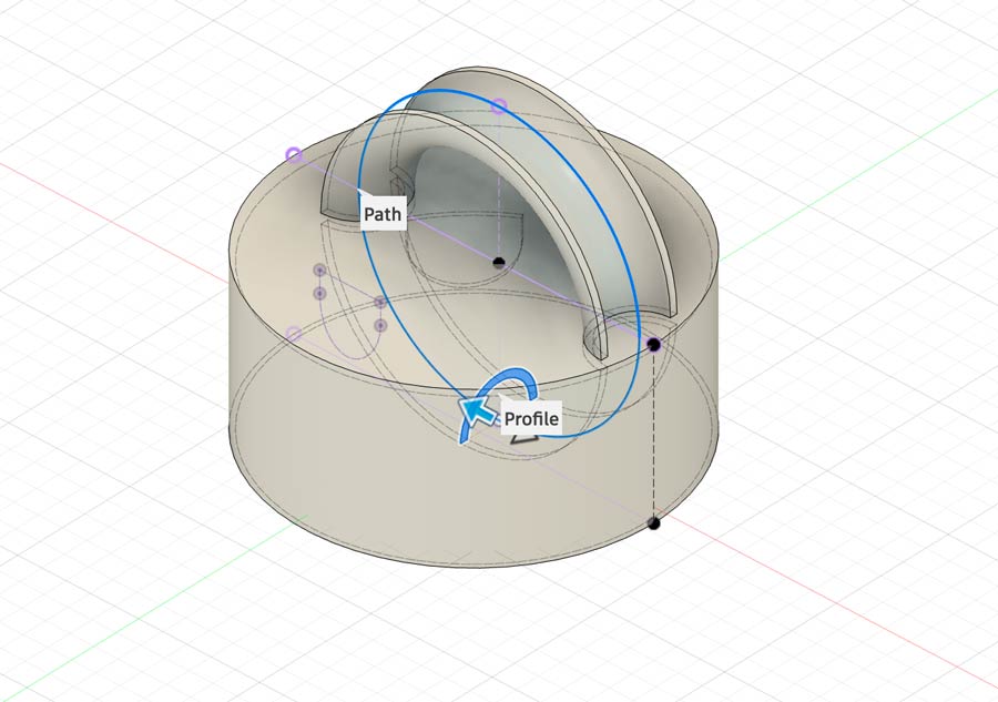
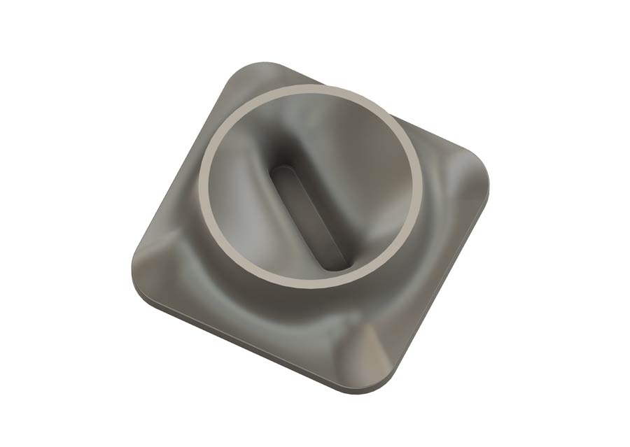
v2 was about addressing the ergonomics more seriously. I updated the braille port, added a thumb rest, and redesigned the handle as its own separate component using a sweep. I also built the base with a loft and cut the knob recess into it.
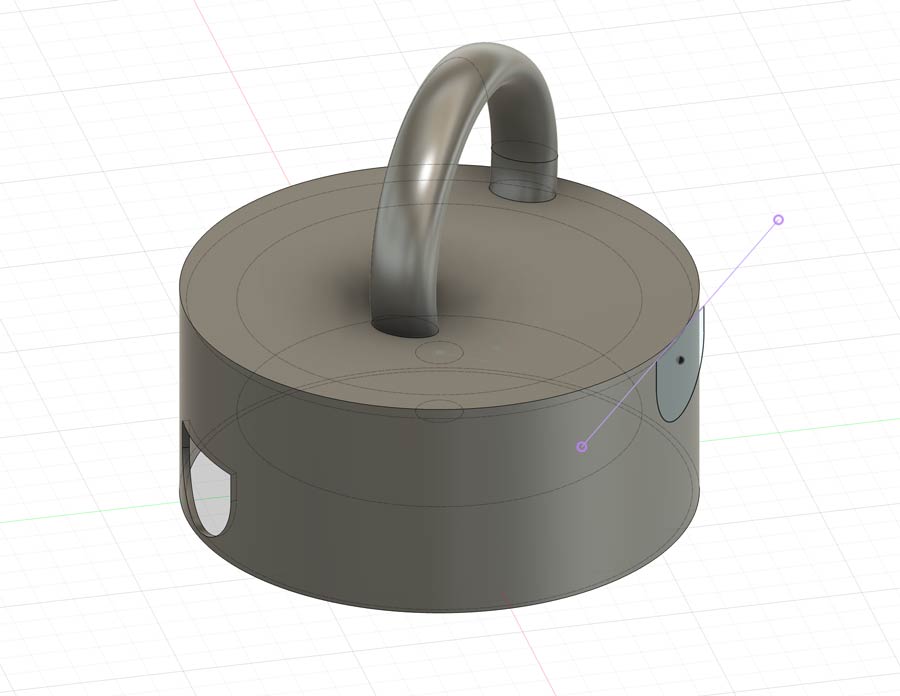
Redesigning the handle with a using sweep, with a new shape and size.
Adding fillets to hard edges.
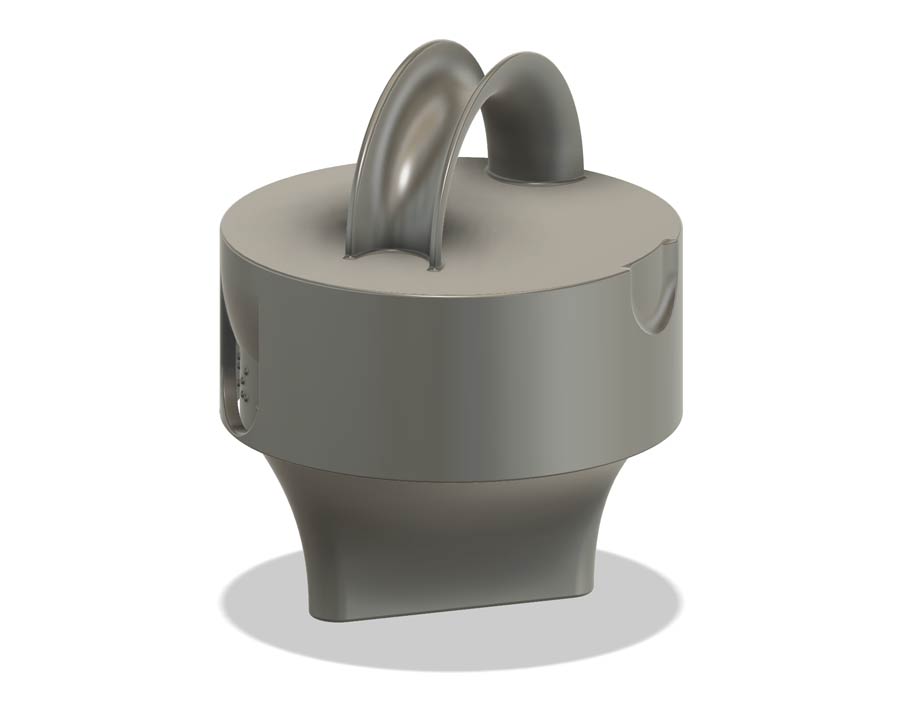
Using a loft to create a base.
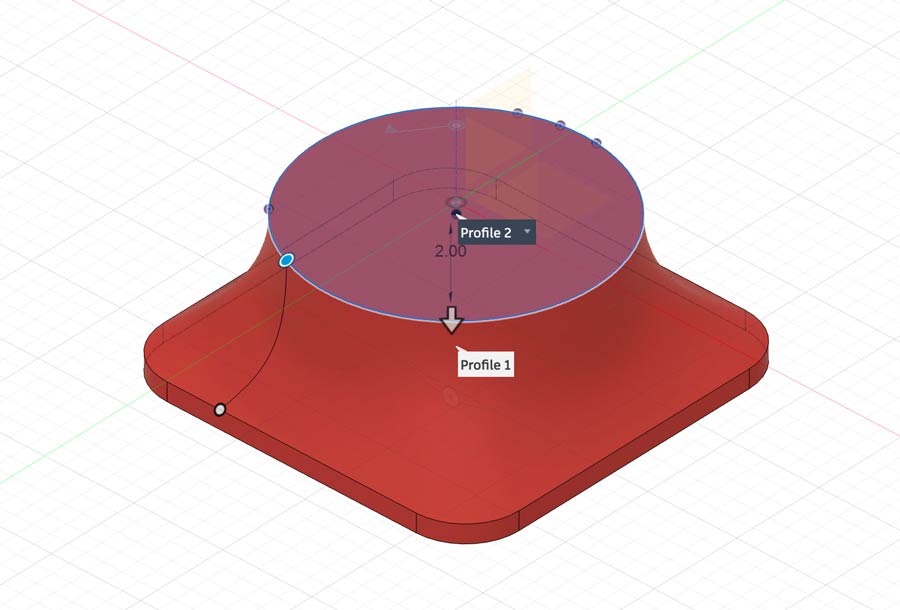
Using knob to cut the base: Comine > Cut
Creating an assembly using a revolute joint.
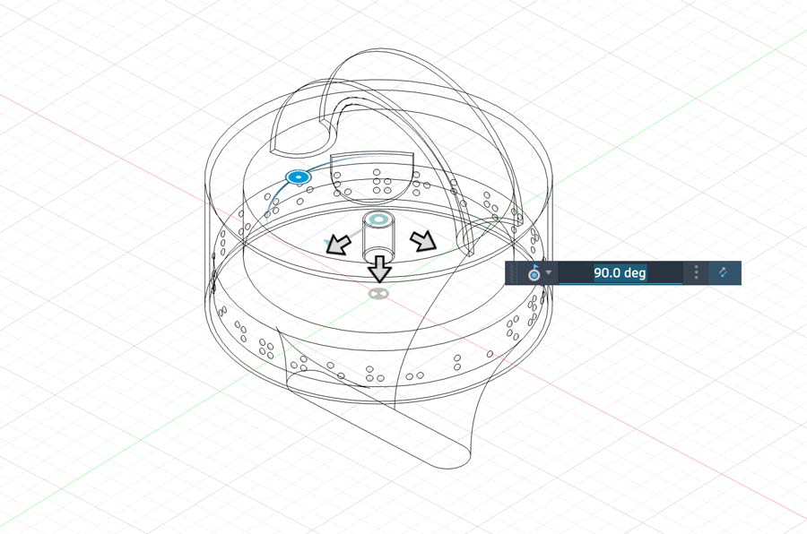
Using section analysis of the timer portion.
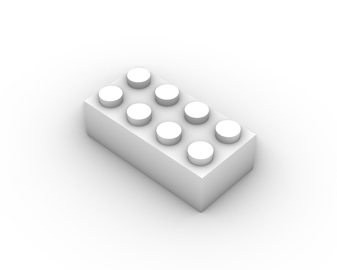
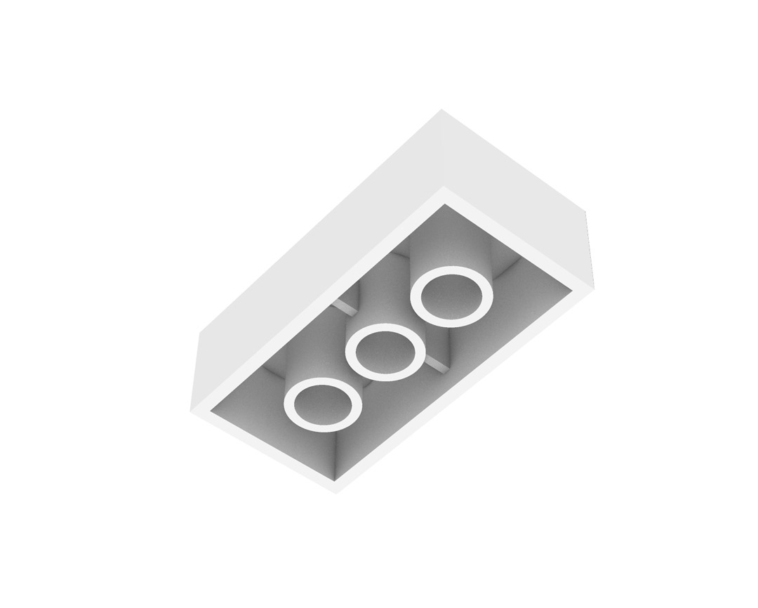
I used Rhino throughout architecture school, so it felt familiar coming back to it. I really missed typing commands. It's still a really intuitive way to model. You type a command name into the command line, hit enter, and Rhino walks you through the inputs — it's much faster than hunting through menus.
My workflow in Rhino starts in 2D: I draw a curve first (using commands like Circle or Rectangle), convert it into a surface using PlanarSrf, and then extrude that surface into a solid with ExtrudeSrf. For the Lego brick, the main body and stud profiles were all built this way. I then used BooleanDifference to hollow out the underside — you select the base body, then the cutter, and Rhino subtracts one from the other. And I used ArrayRect to repeat the studs across the grid, defining the number of rows, columns, and spacing in one step.
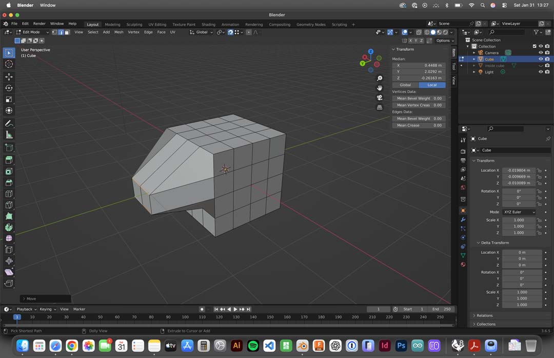
Dhrishya gave us an intro to Blender alongside Shiv. The interface is powerful but deeply unintuitive, especially coming from tools where the mental model is more organized (like Fusion). I followed along with the basics: extruding and moving faces, subdividing, and using the array modifier.
The "pushing and pulling" is done in Edit Mode (Tab to toggle). Selecting a face and pressing E extrudes it — Blender immediately constrains the movement so you can type a distance. Pressing G grabs the selection and lets you move it freely, or along a constrained axis (G → Z, for example, locks to the Z axis). It's functional once you memorize the hotkeys, but the keybinding-first mental model is a steep onramp.
I decided Blender might be worth learning for rendering, but I don't want to use it for modelling.
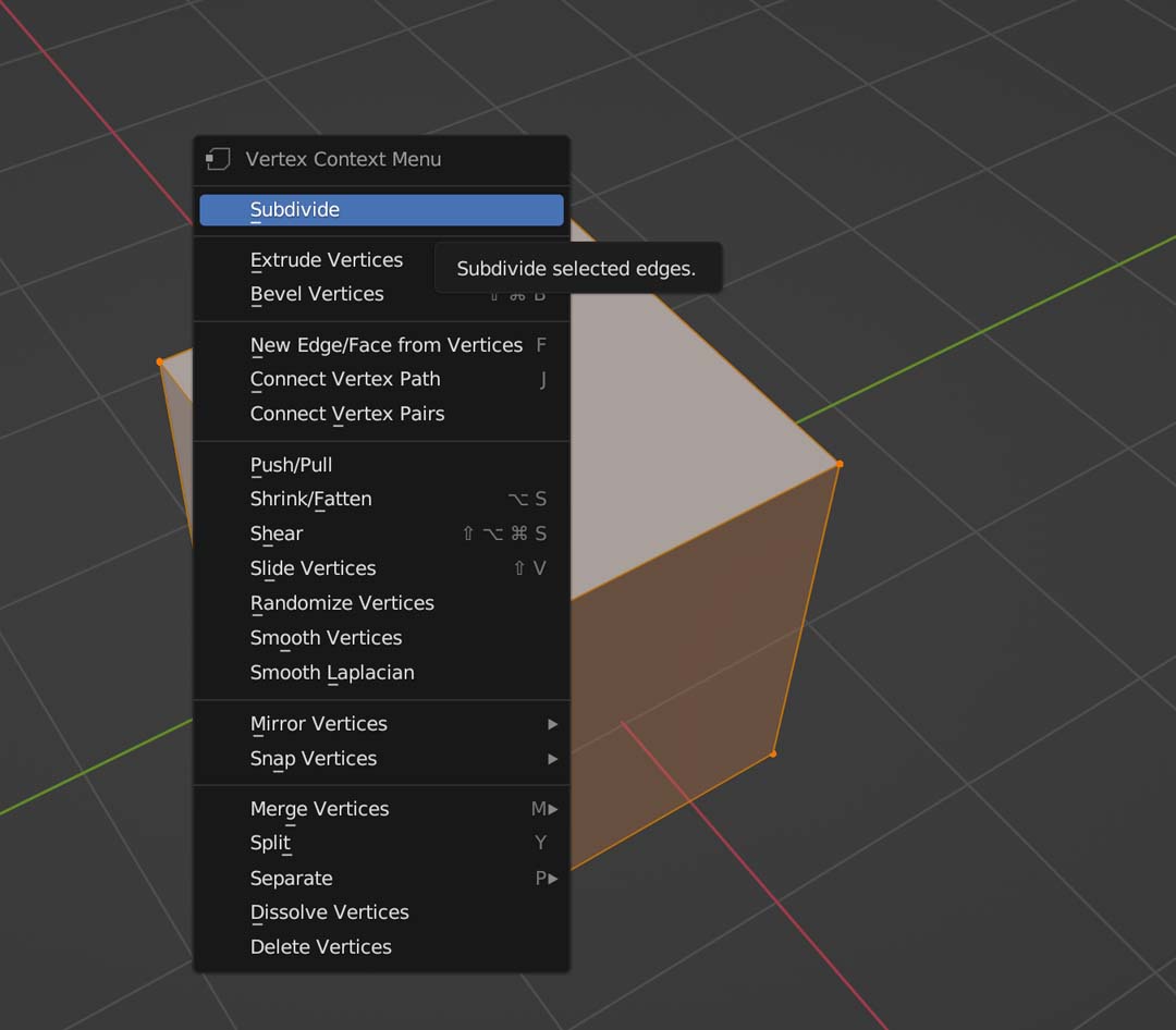
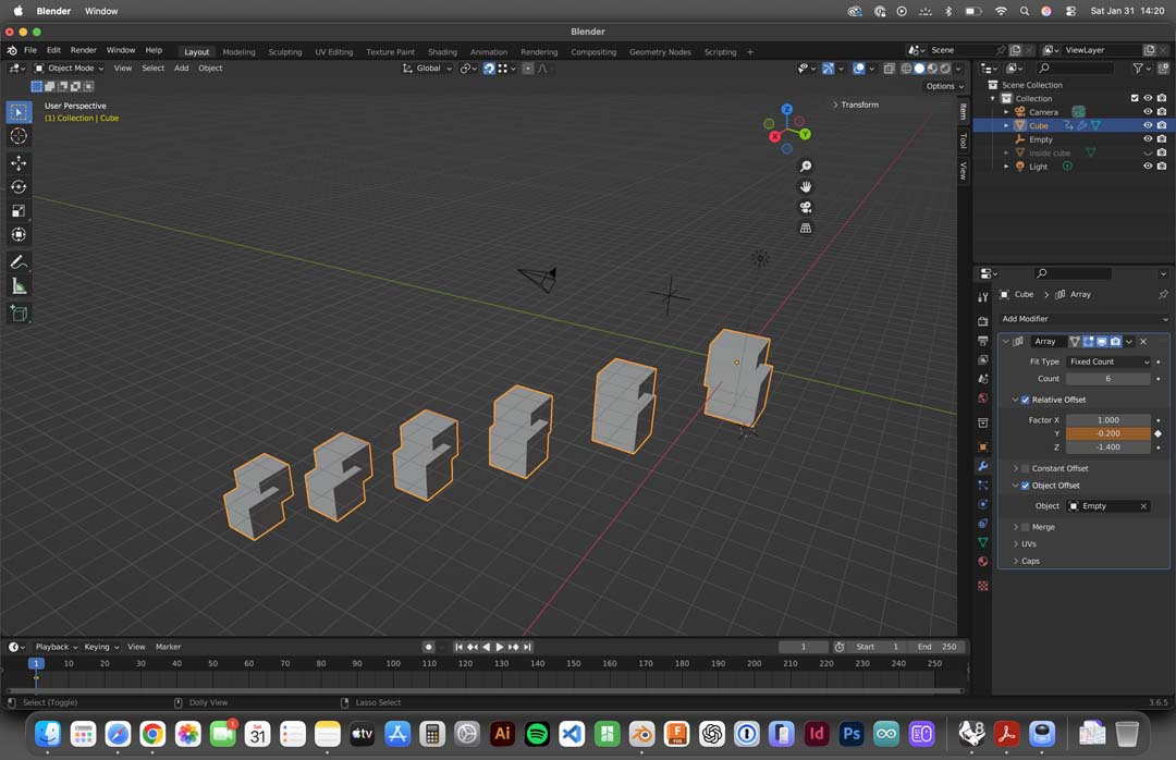
After exploring Rhino and Blender, coming back to Fusion felt like a relief. I like how organized it is. The parametric timeline is fantastic for going back and modifying an operation from early in the process. It's also very visual: you can look at the timeline and understand exactly what you did and in what order.
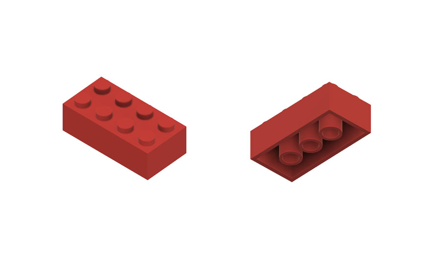
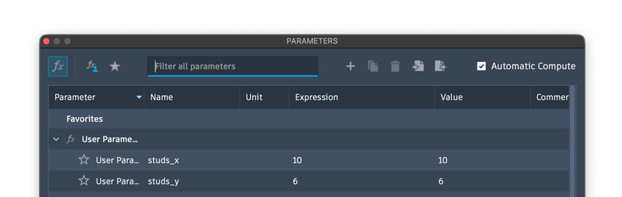
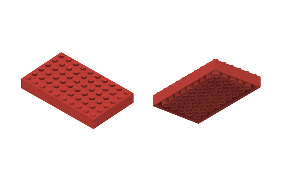
As a first parametric exercise, I modelled a 2x4 Lego brick using Fusion's parametric tools. The goal was to understand how changing a single parameter (stud count in x and y directions) propagates through the entire model automatically.
The core workflow in Fusion is Sketch → Extrude: you draw a 2D profile on a plane, then pull it into 3D using the Extrude command (shortcut E). For the studs, I sketched a circle on the top face and extruded it upward. I then used Rectangular Pattern (under Create > Pattern) to duplicate the stud across the grid — you set the feature to repeat, define X and Y direction vectors, and drive the count from parameters. All the key dimensions (body height, wall thickness, stud diameter, stud count X/Y) were defined upfront using Modify > Change Parameters. Changing a parameter value there cascades through every sketch constraint and feature that references it, so the whole model updates instantly.
Here's an overview of how I go about preparing my images and videos for the web.
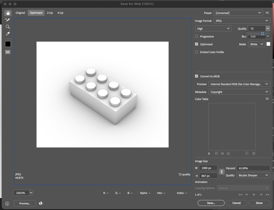
For single images I often just use the Save for web tool in Photoshop: File > Export > Save for Web...
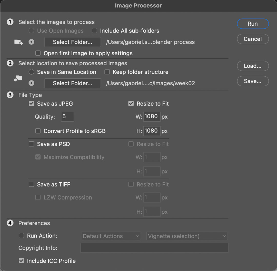
When I have many images to process at the same time, I use Photoshops image processor tool, which batch resizes images for you: File > Scripts > Image Processor...
For video compression, I've been using YouTube to upload my videos and redownload them once they're uploaded. YouTube has a good compression algorithm and allows you to download your videos directly as mp4s.