Individual assignment
beating heart
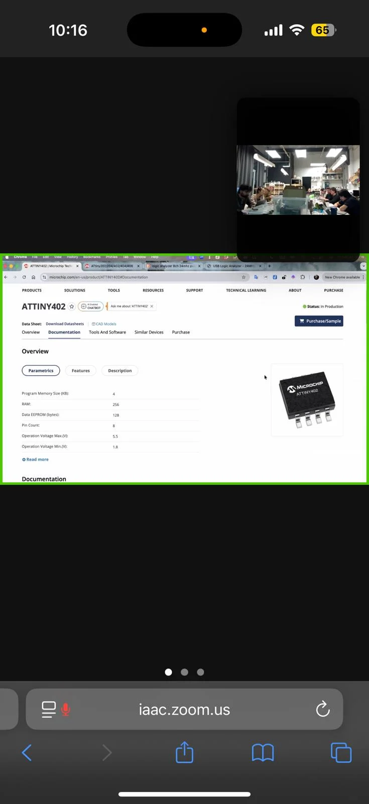
for this week´s asssignment, I want to create a pcb that simulates a beating heart usinf an ATtiny412 microcontroller unit with LED´s blinking respective to a human heartbeat.
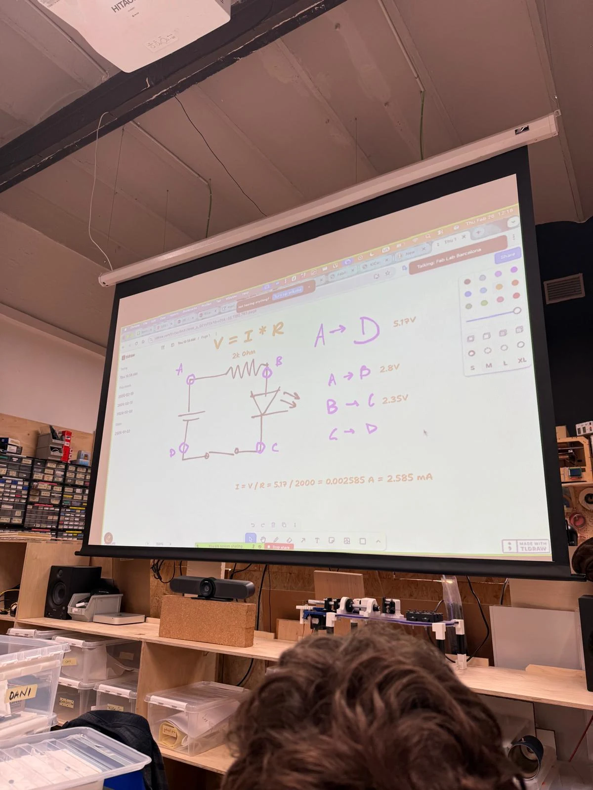
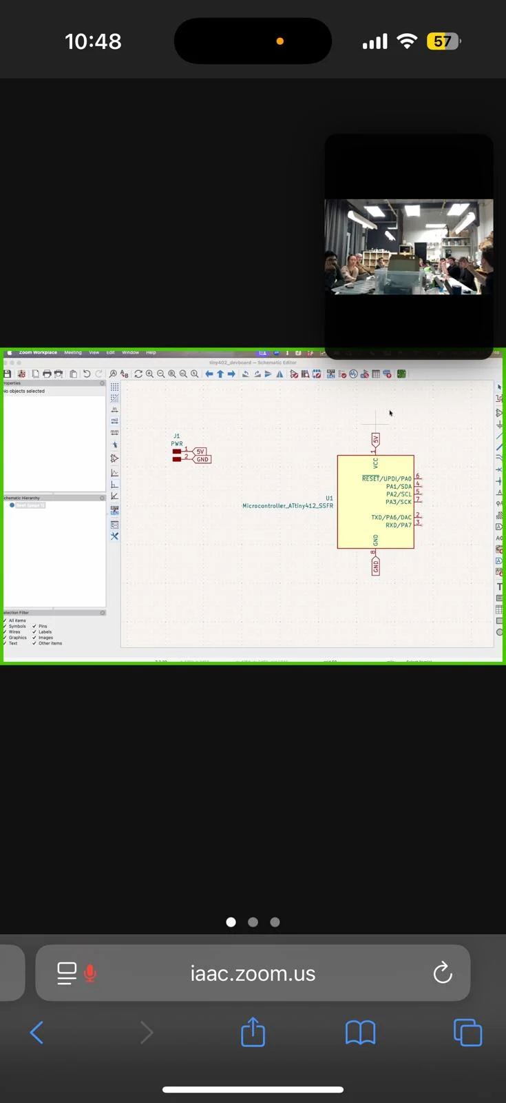
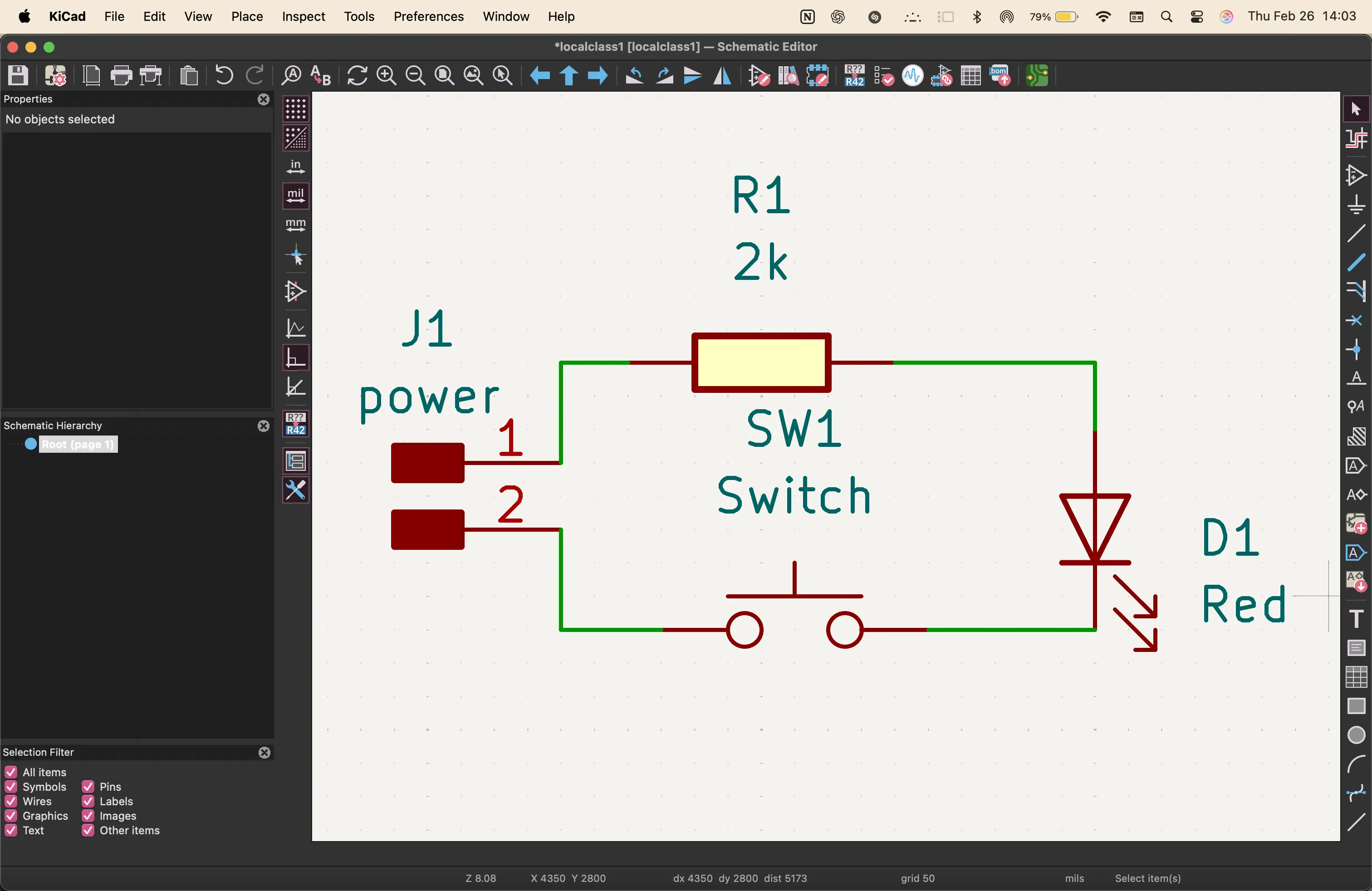
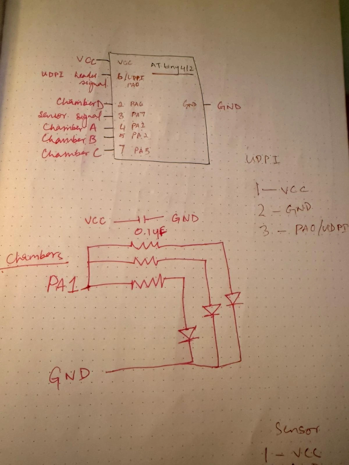
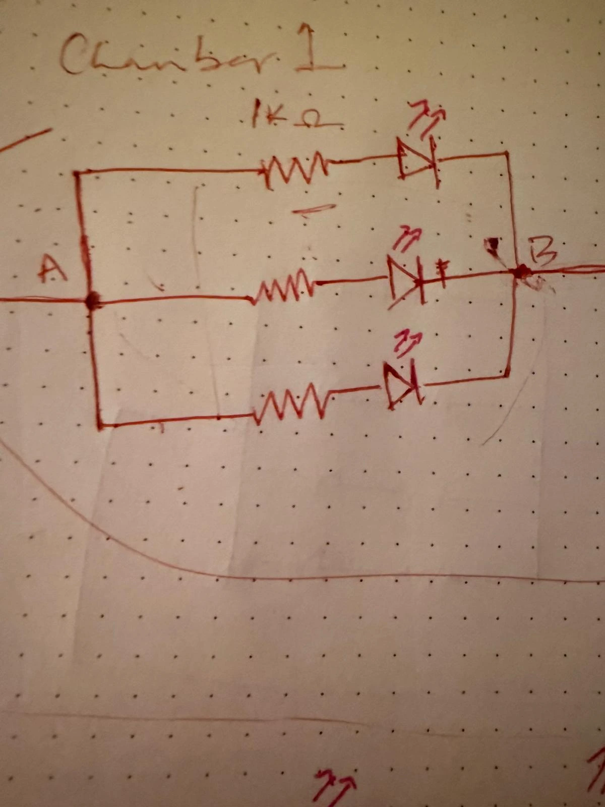
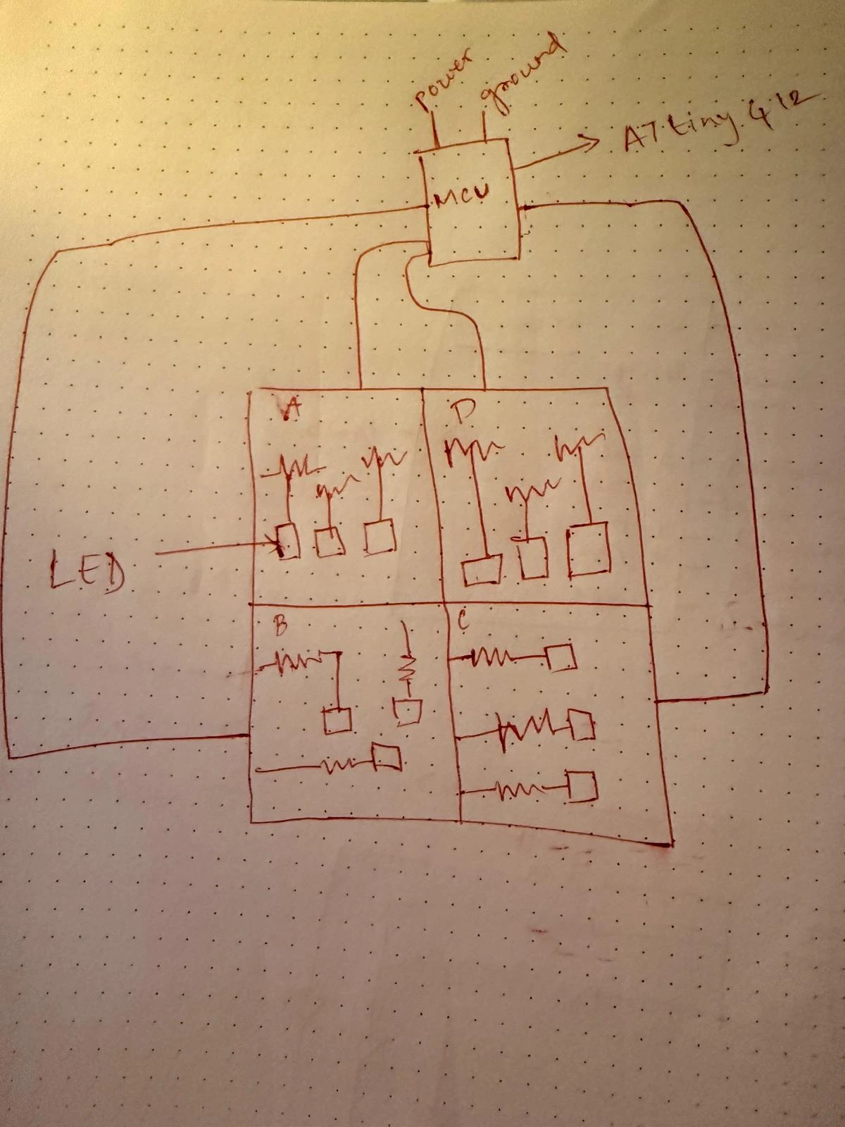
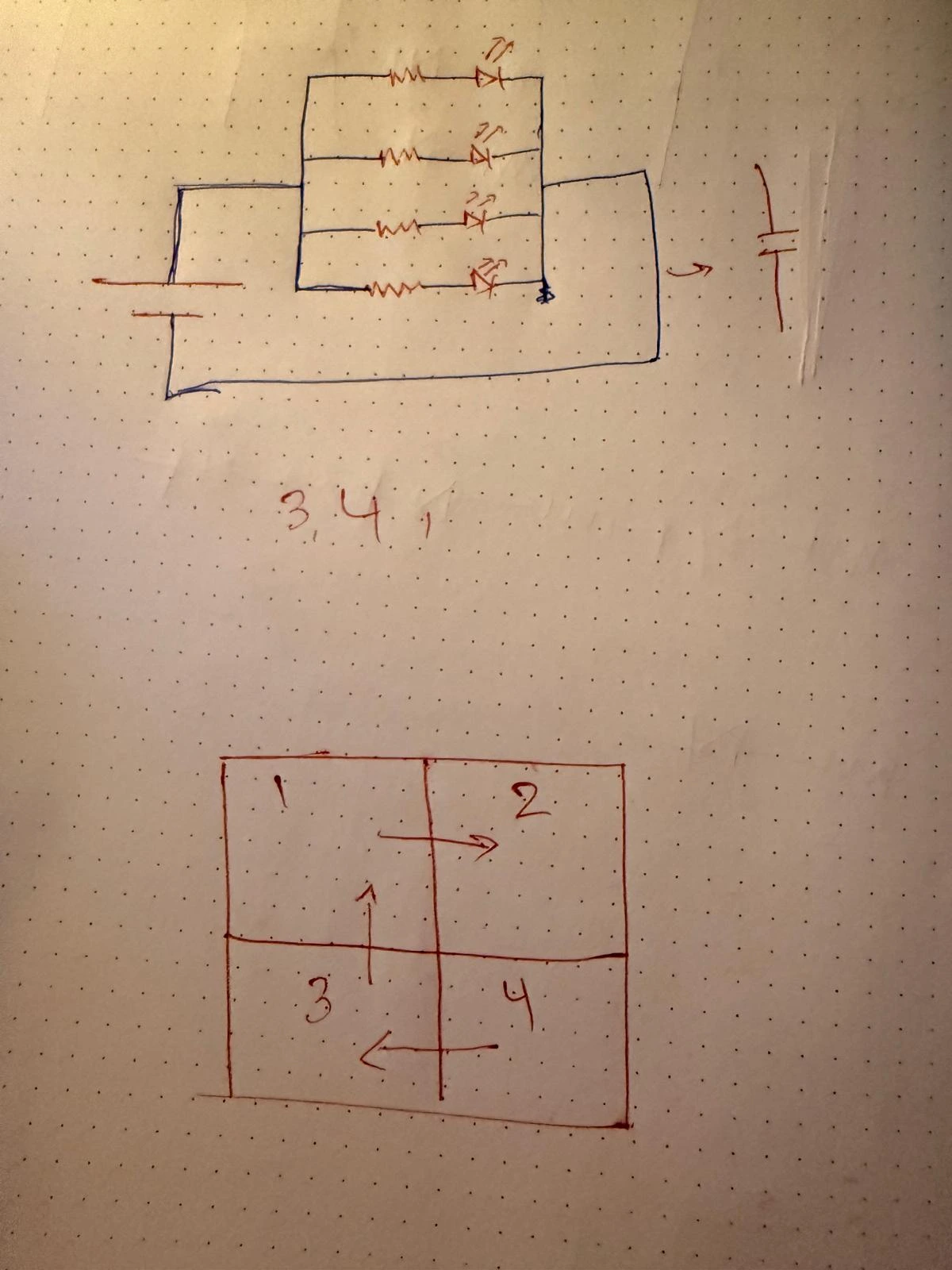
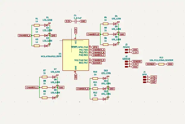
the first step was to understand the circuit
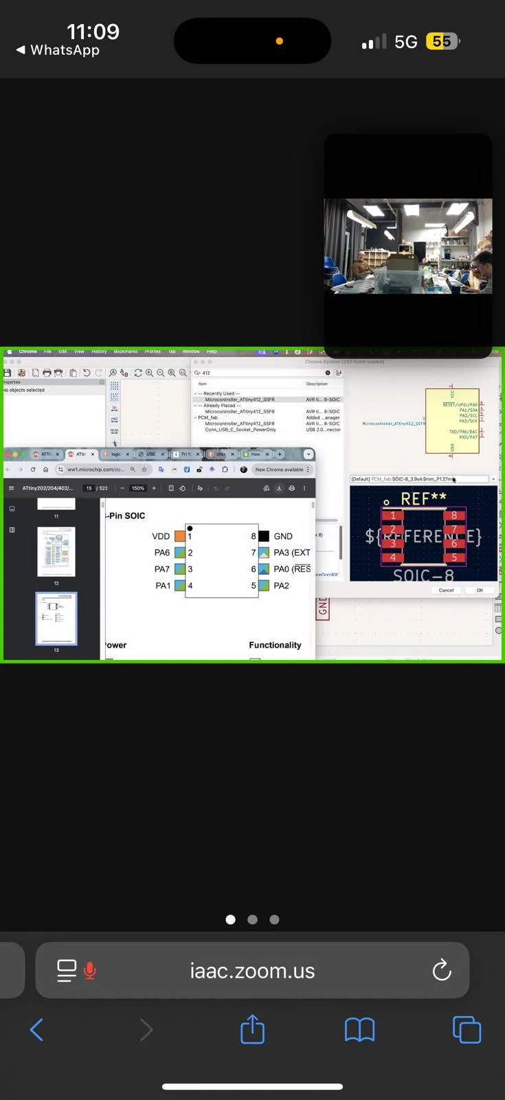
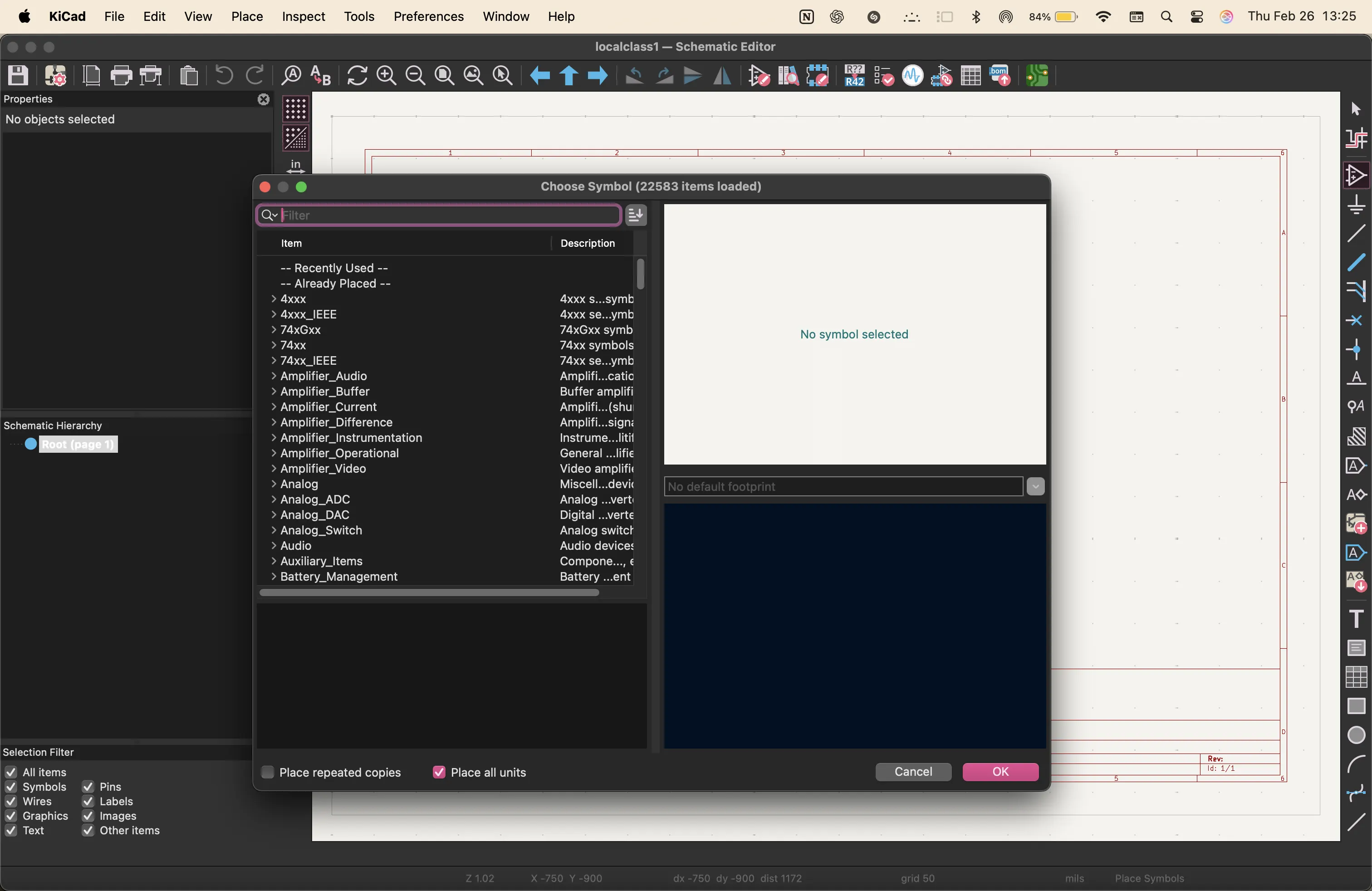
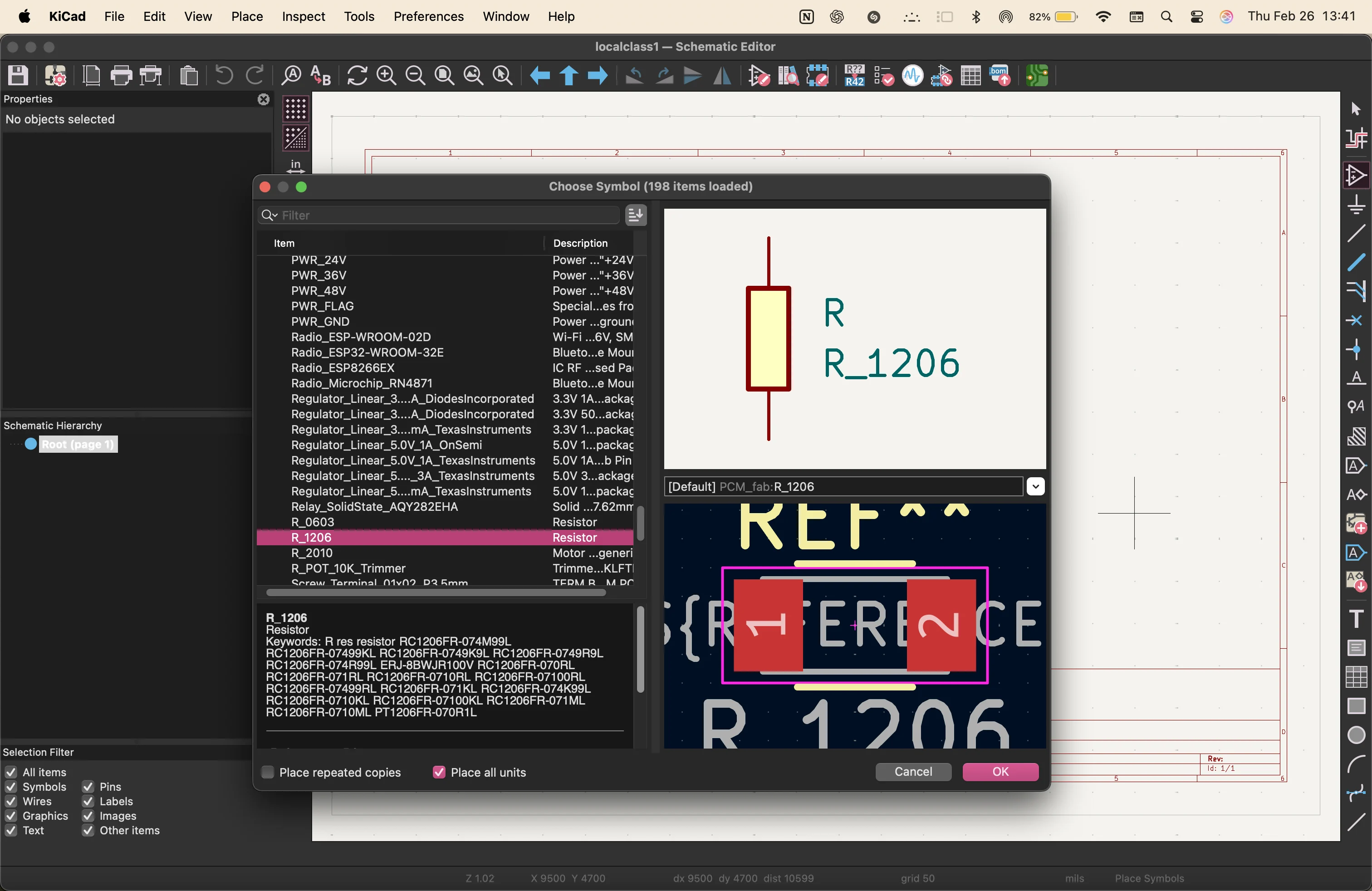
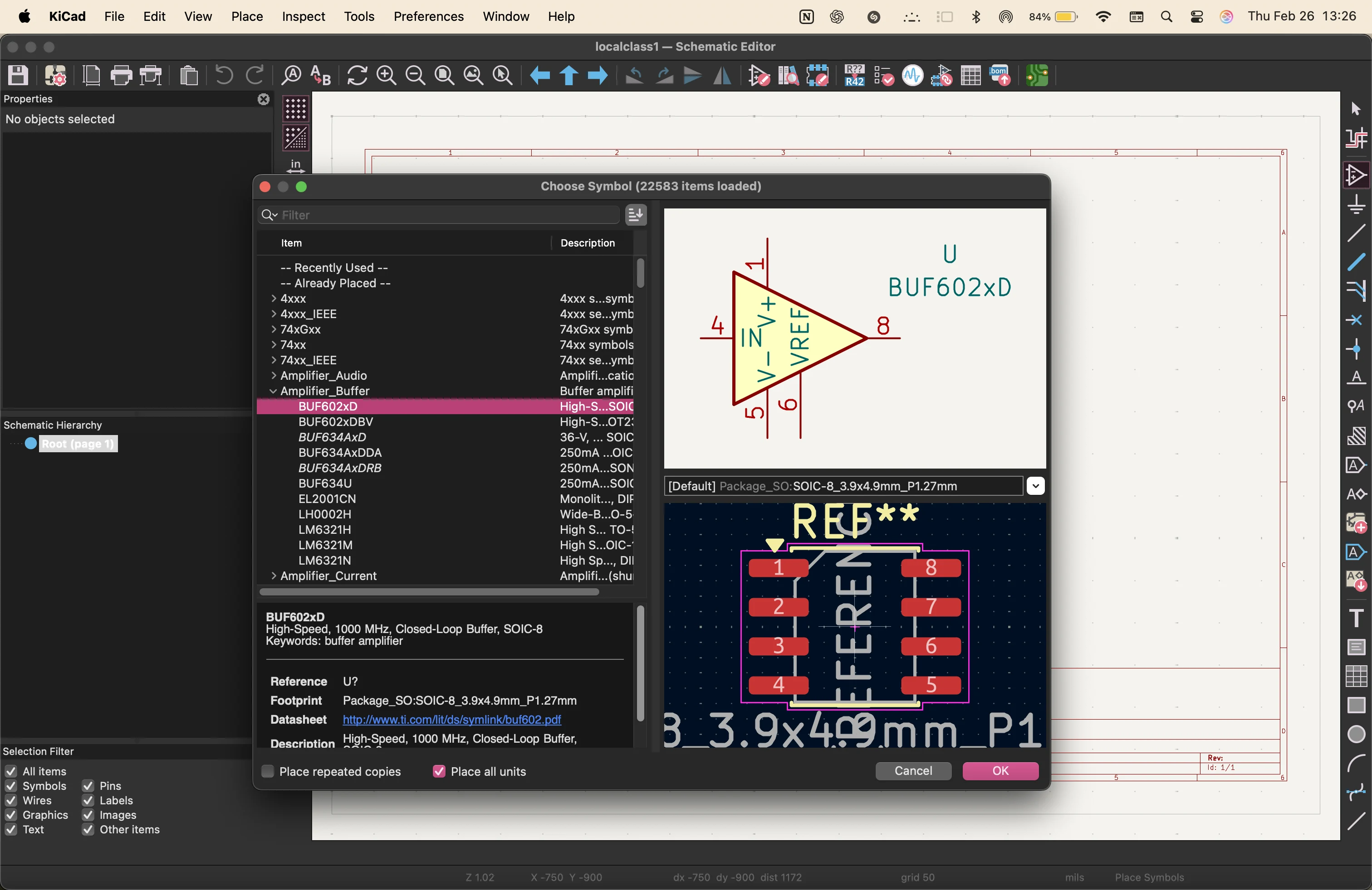
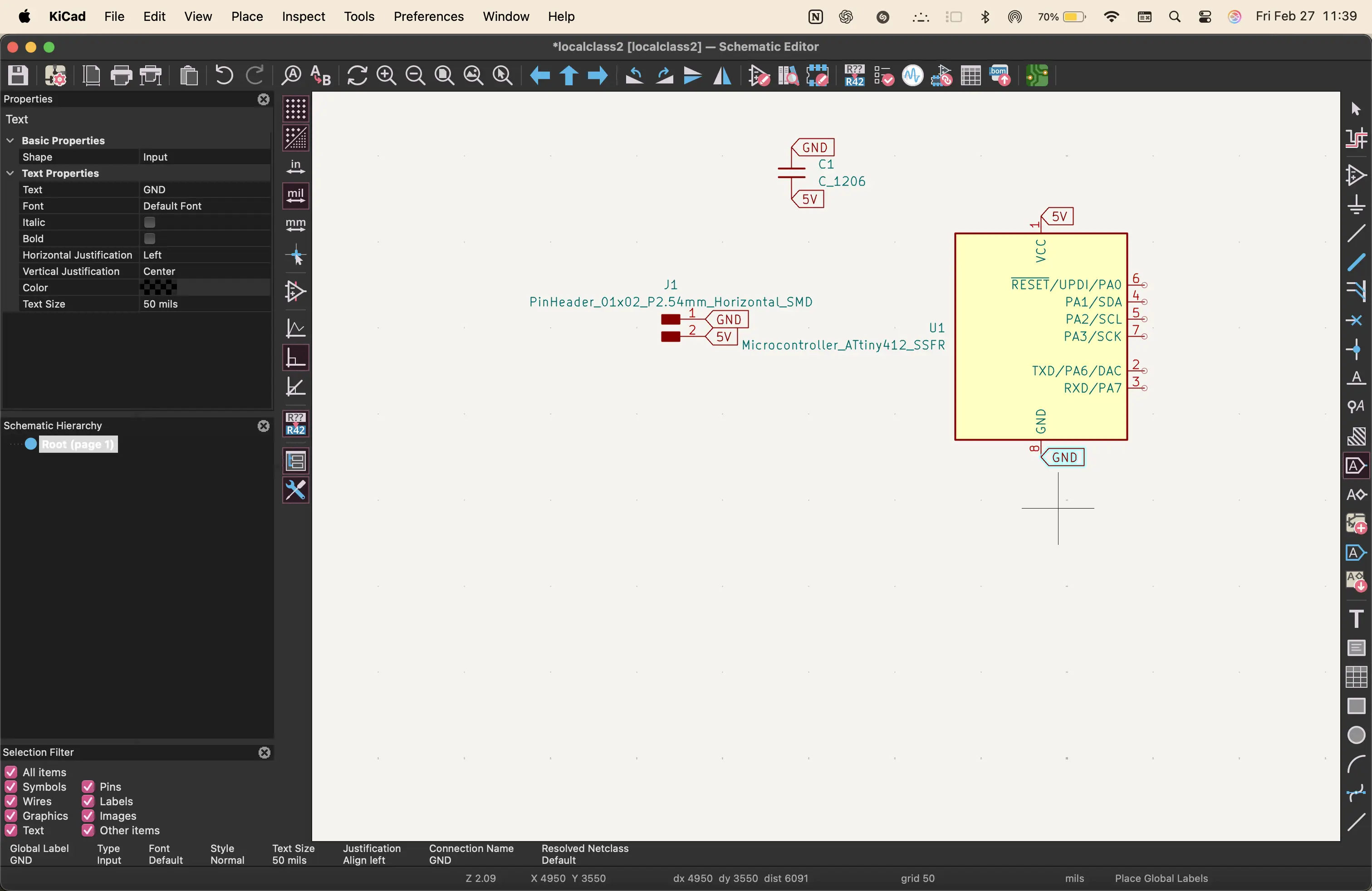
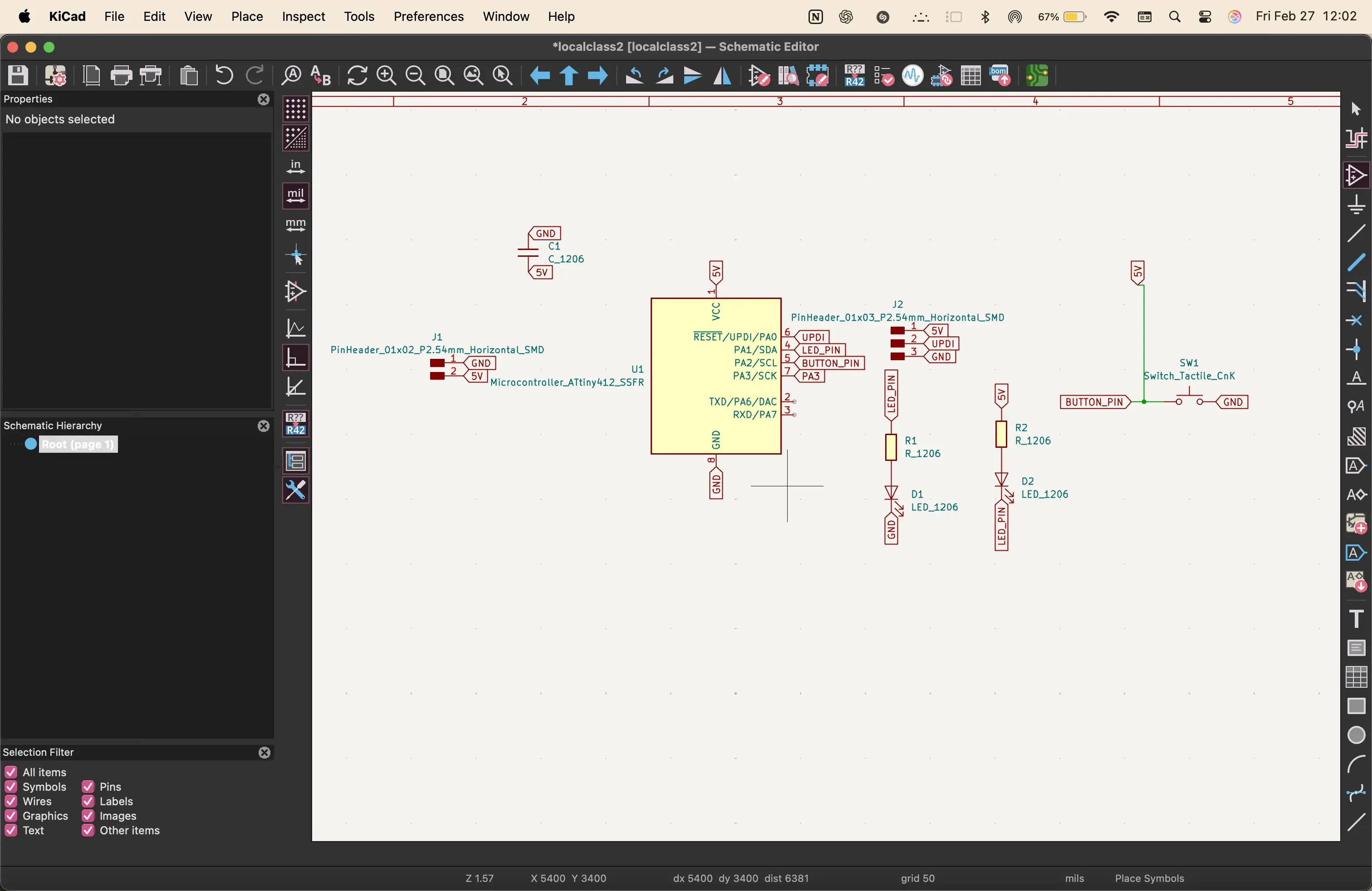
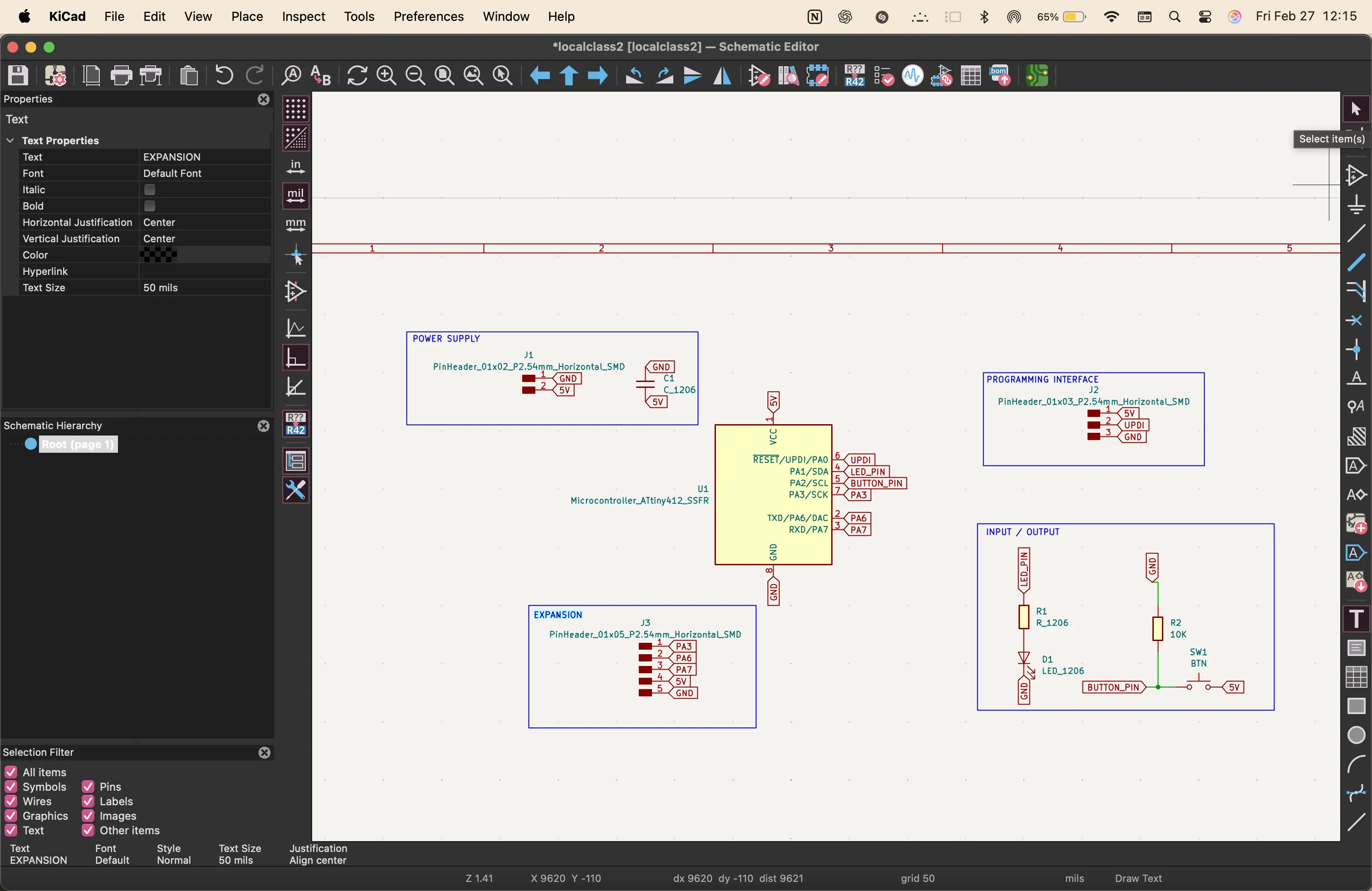
next, i went to Kicad to make the schematic with all the components.
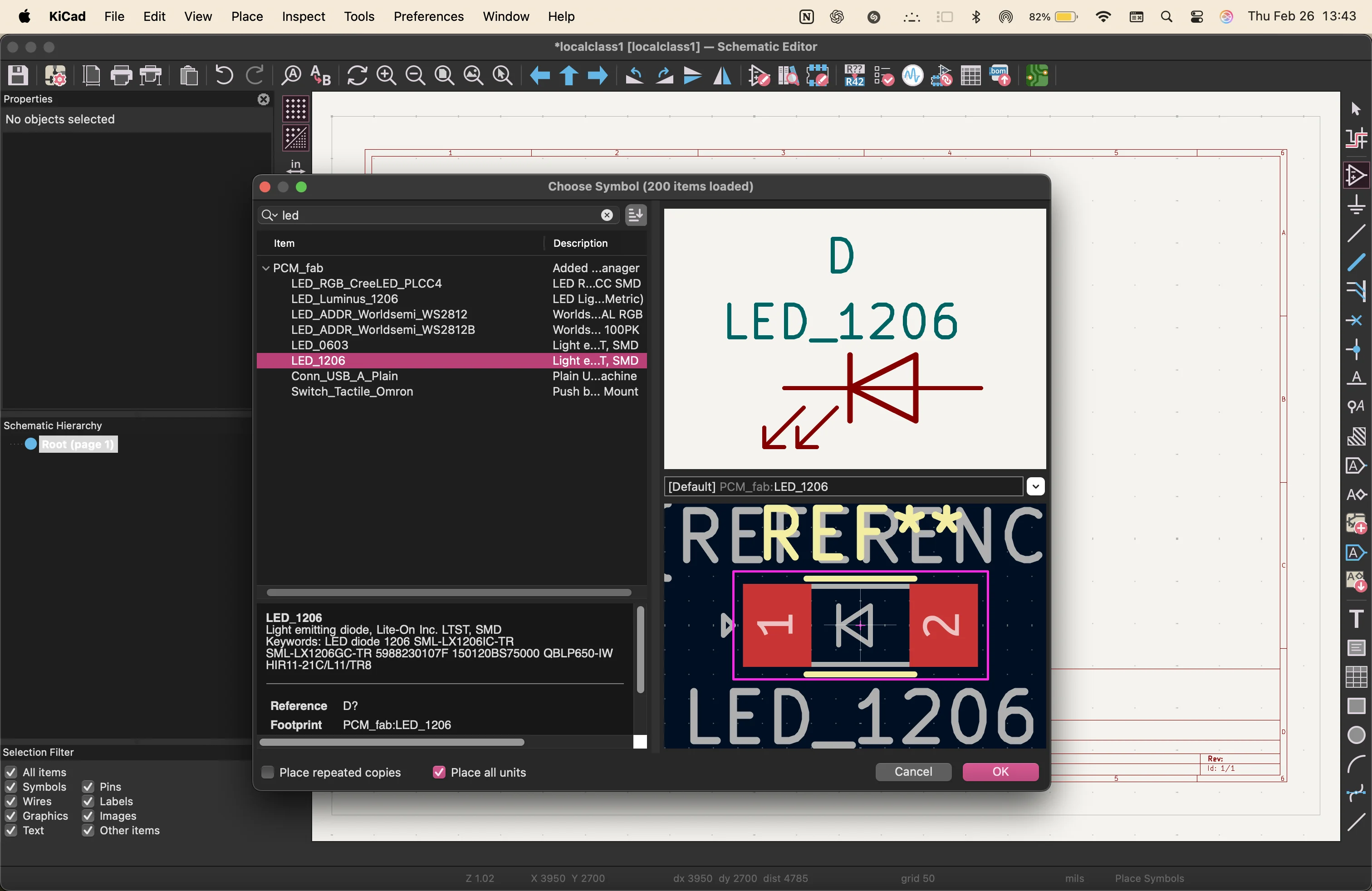
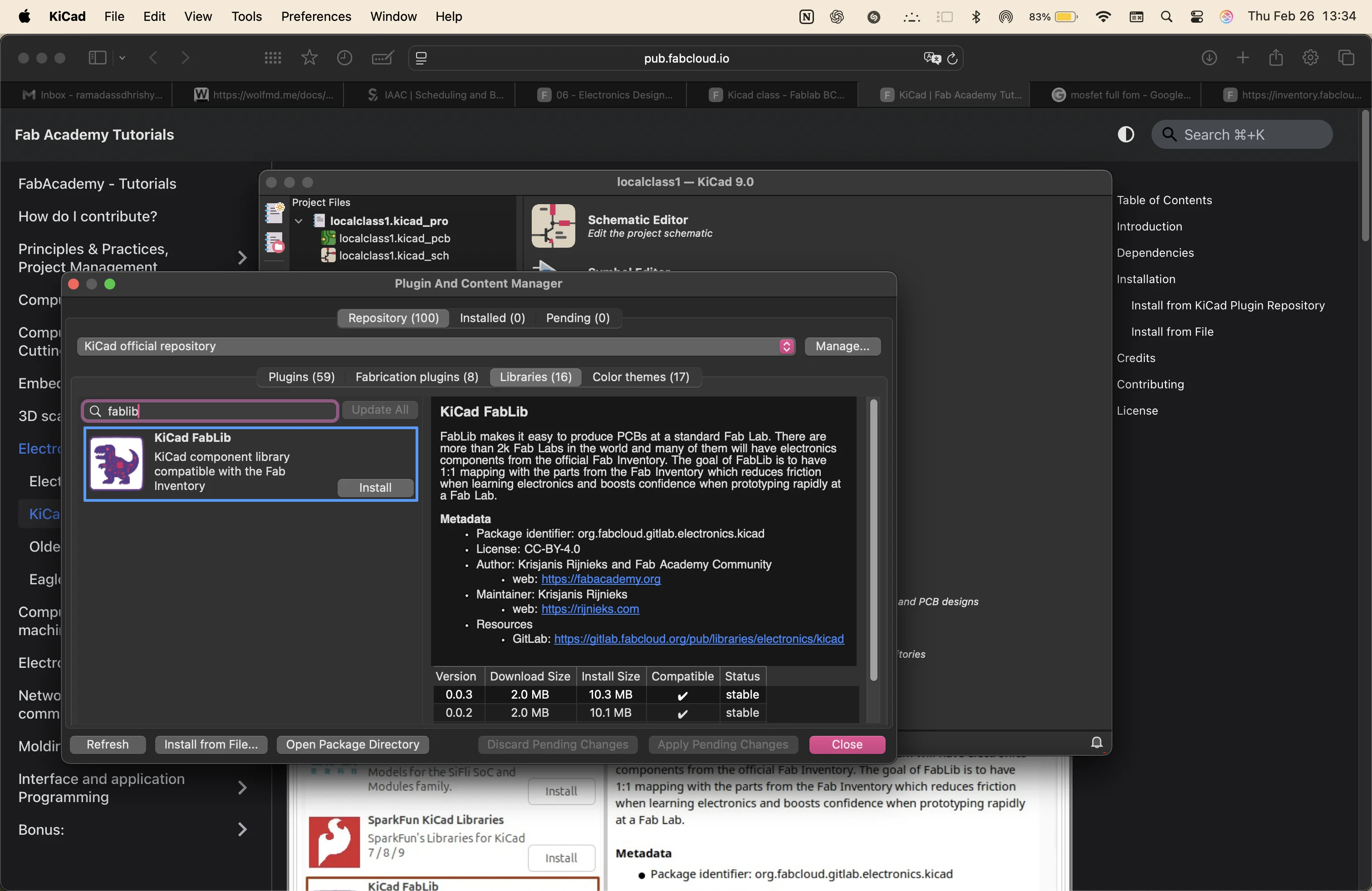
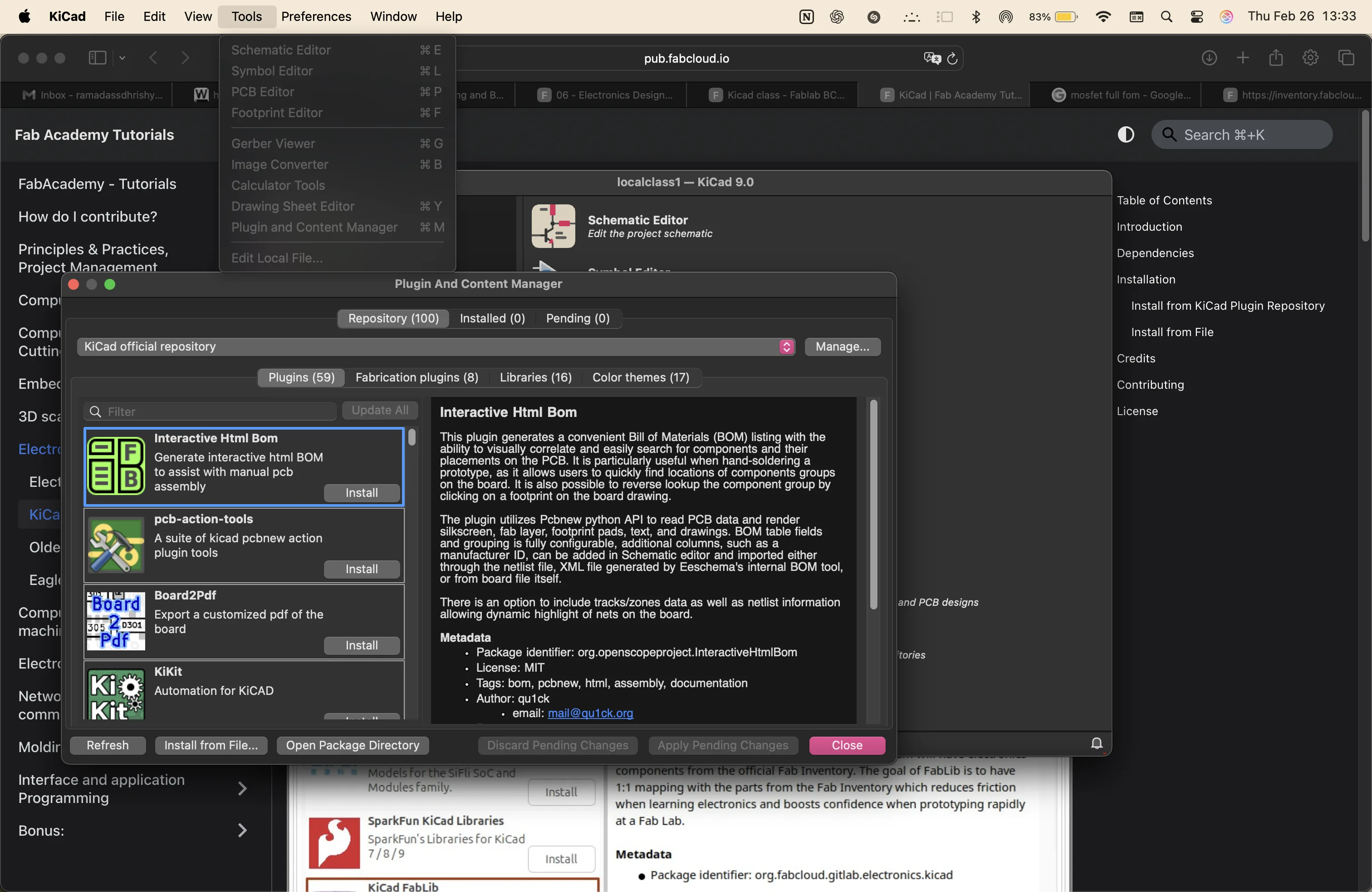
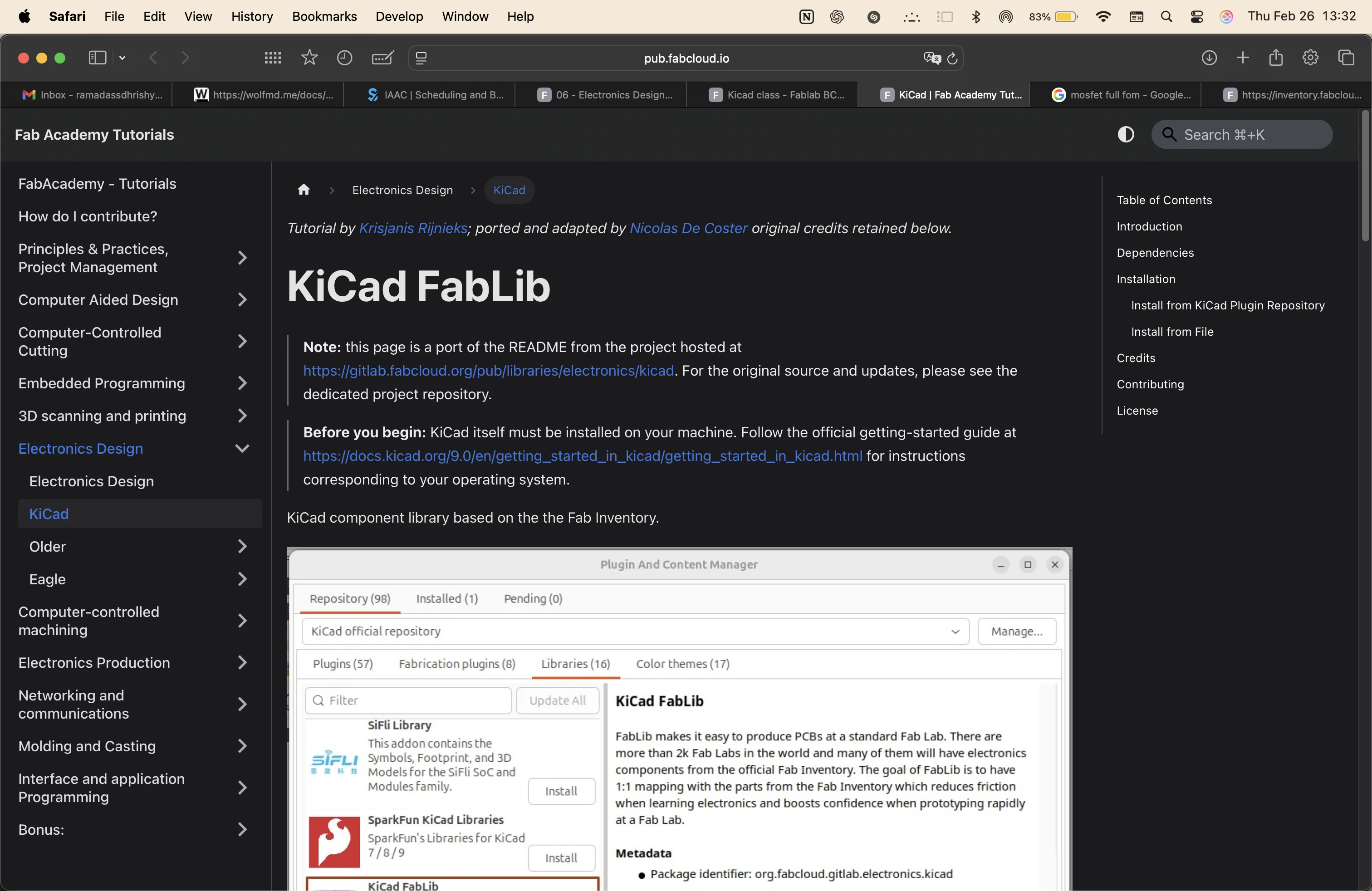
earlier in the class, we downloaded the Fablib component library. More shown in the notes.
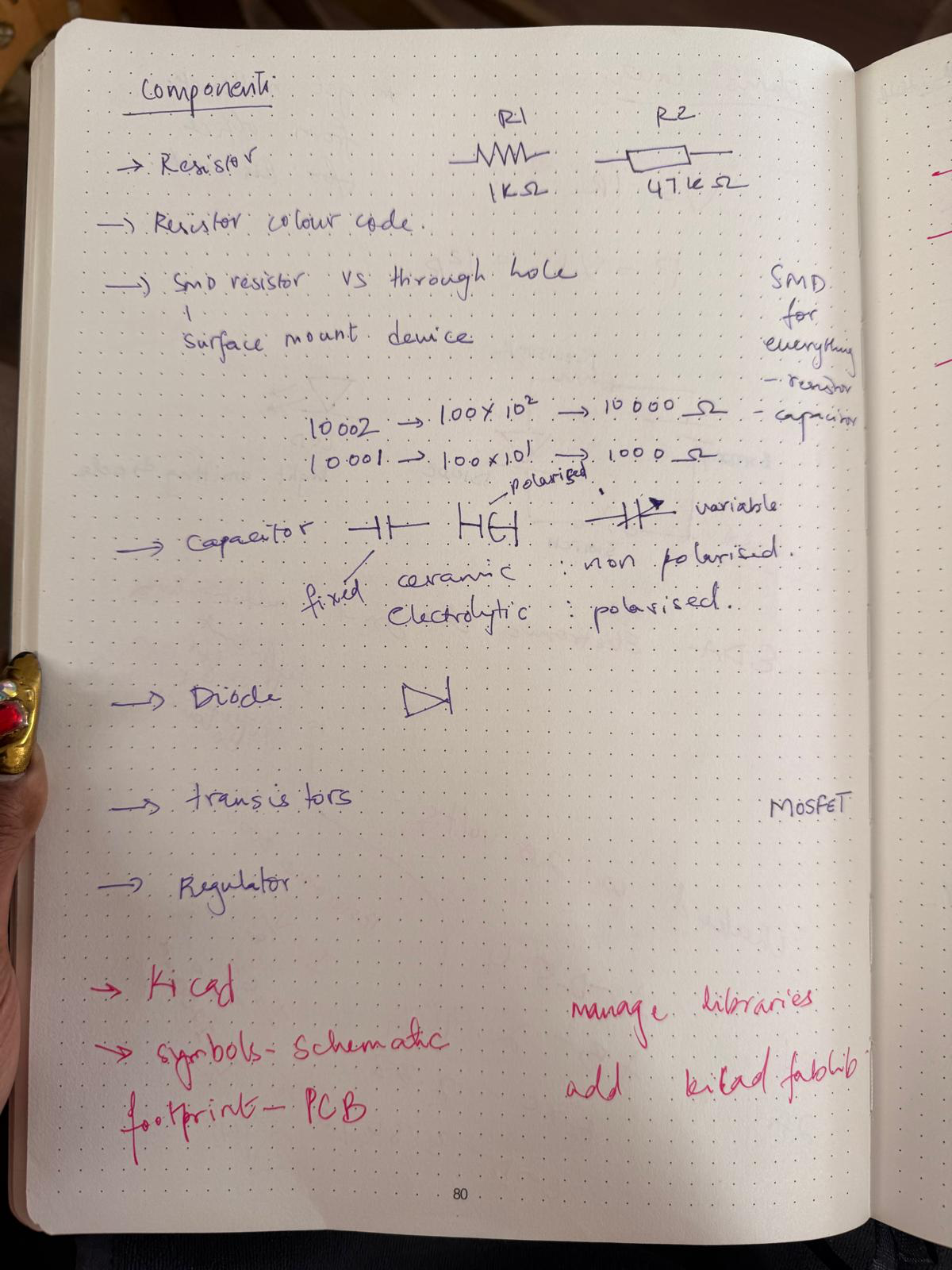
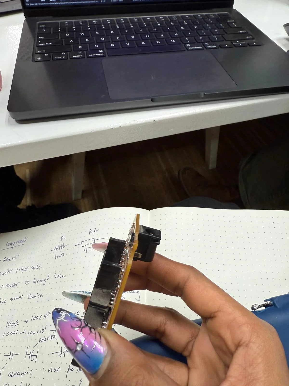
component list
- ATtiny412 microcontroller unit
- 12x 1k ohm resistors
- 1x 10k ohm pull-down resistors
- 12x LEDs
- 1x 0.1uF capacitor
- 3x pins for power, sensor and updi
after importing the components i needed, I renamed the serial numbers and added tags to every open connection
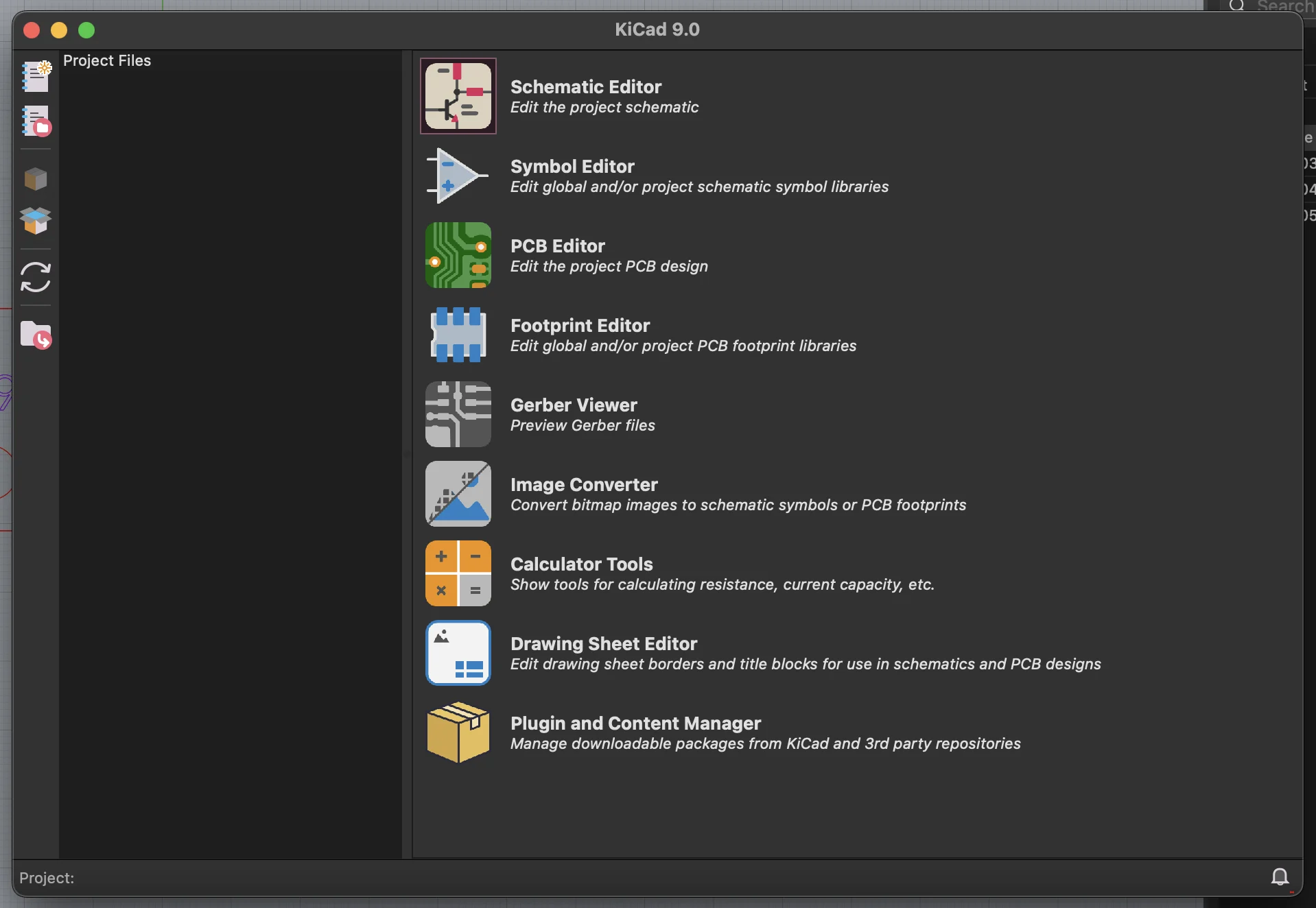
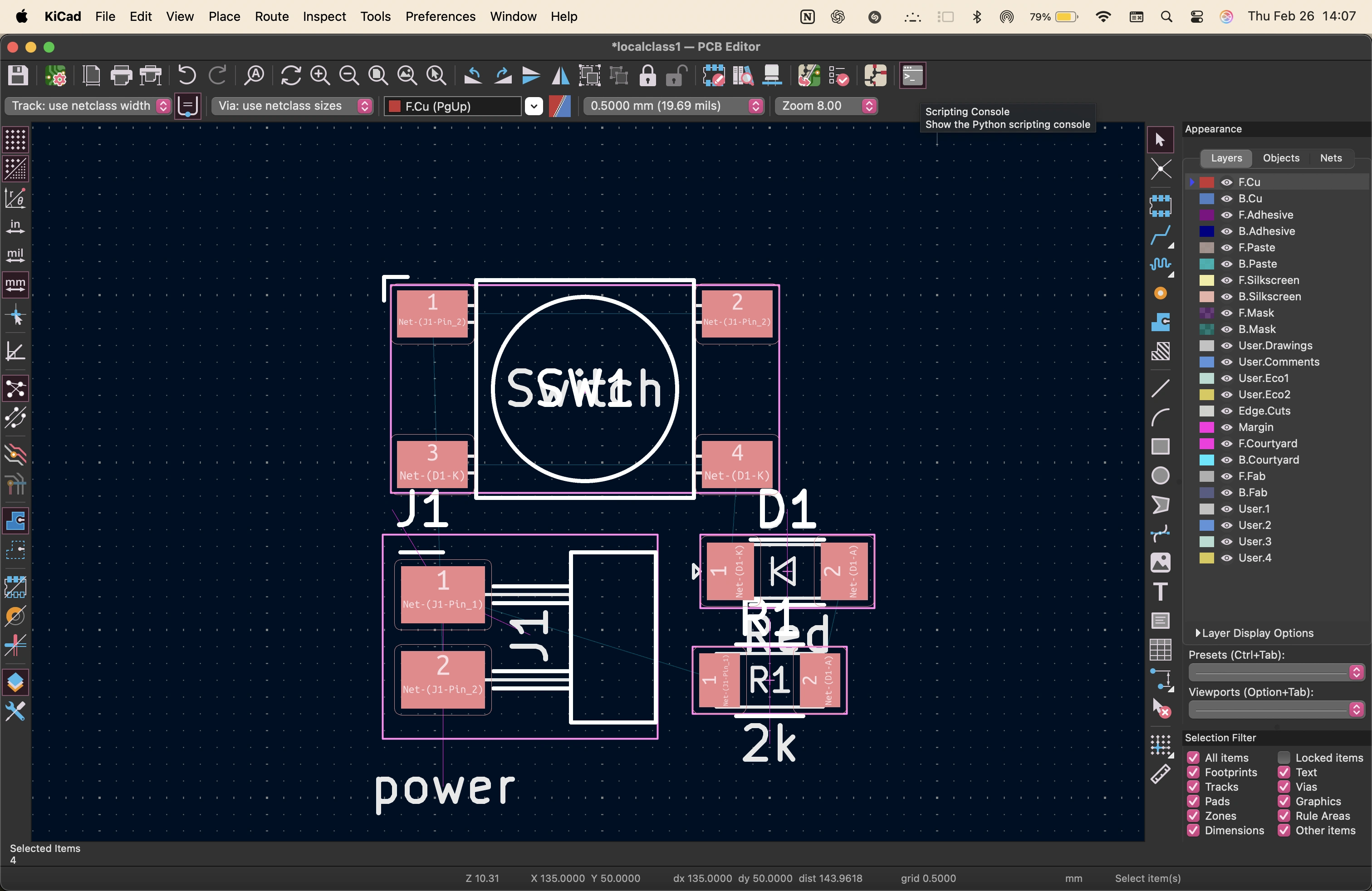
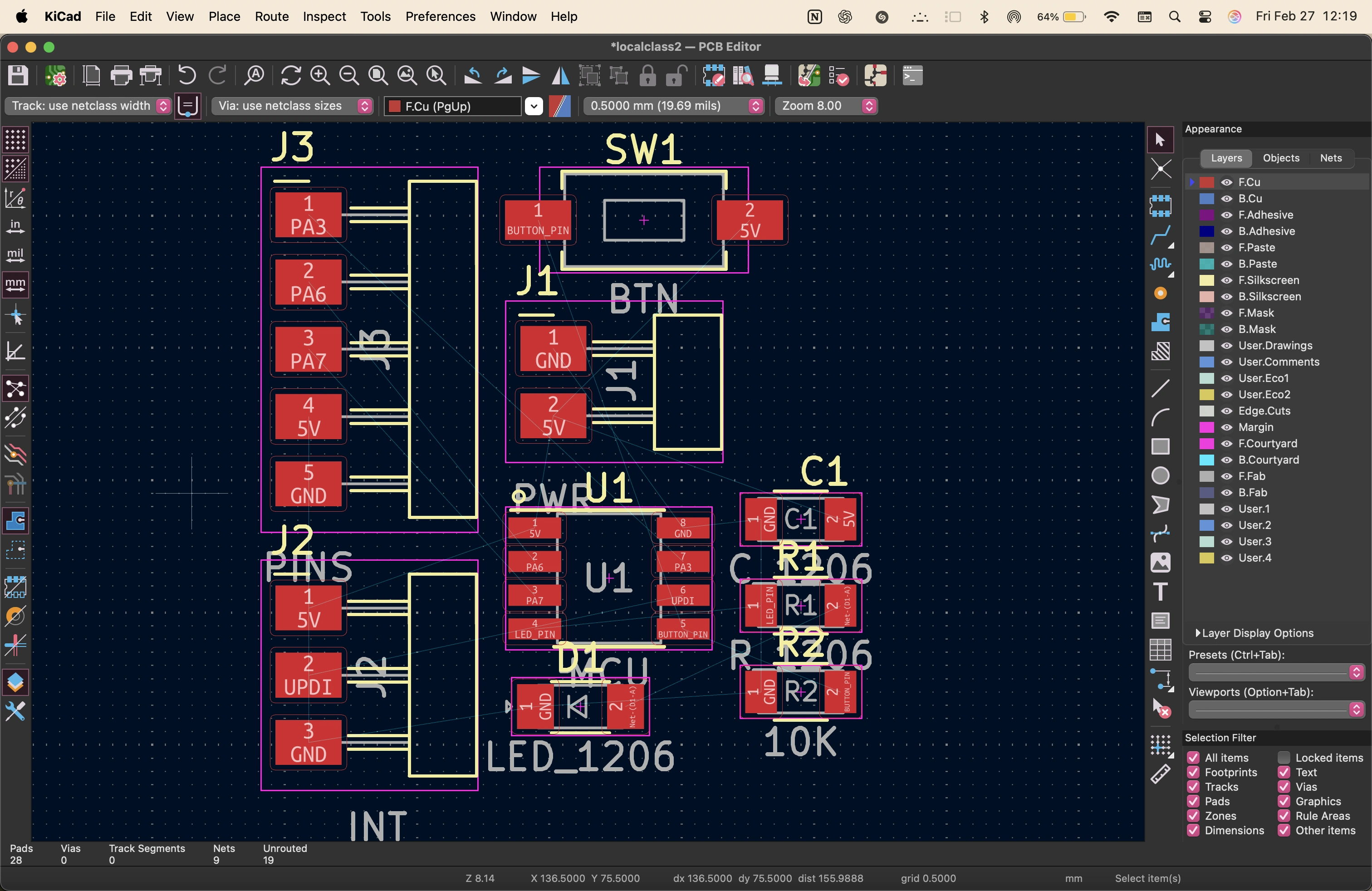
pcb design
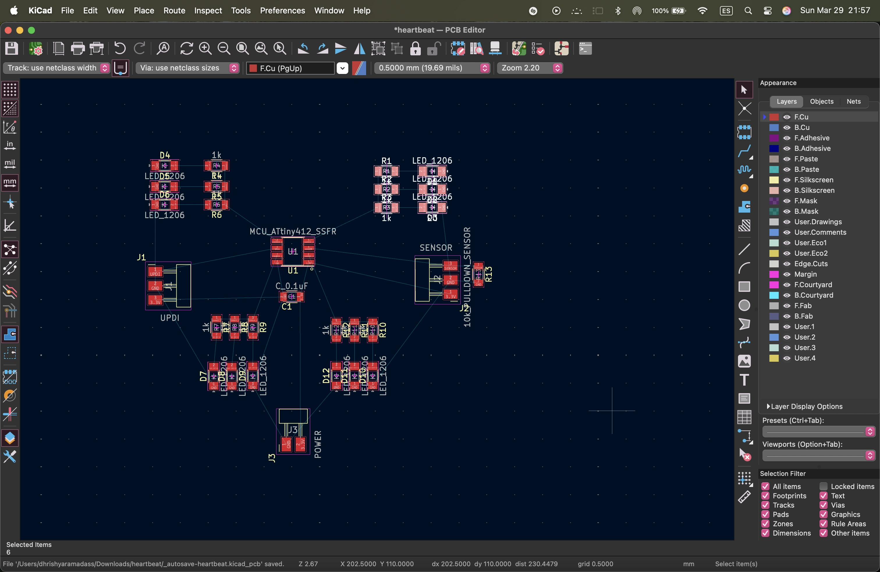
on kicad, i clicled on the pcb icon and updated the schematic.
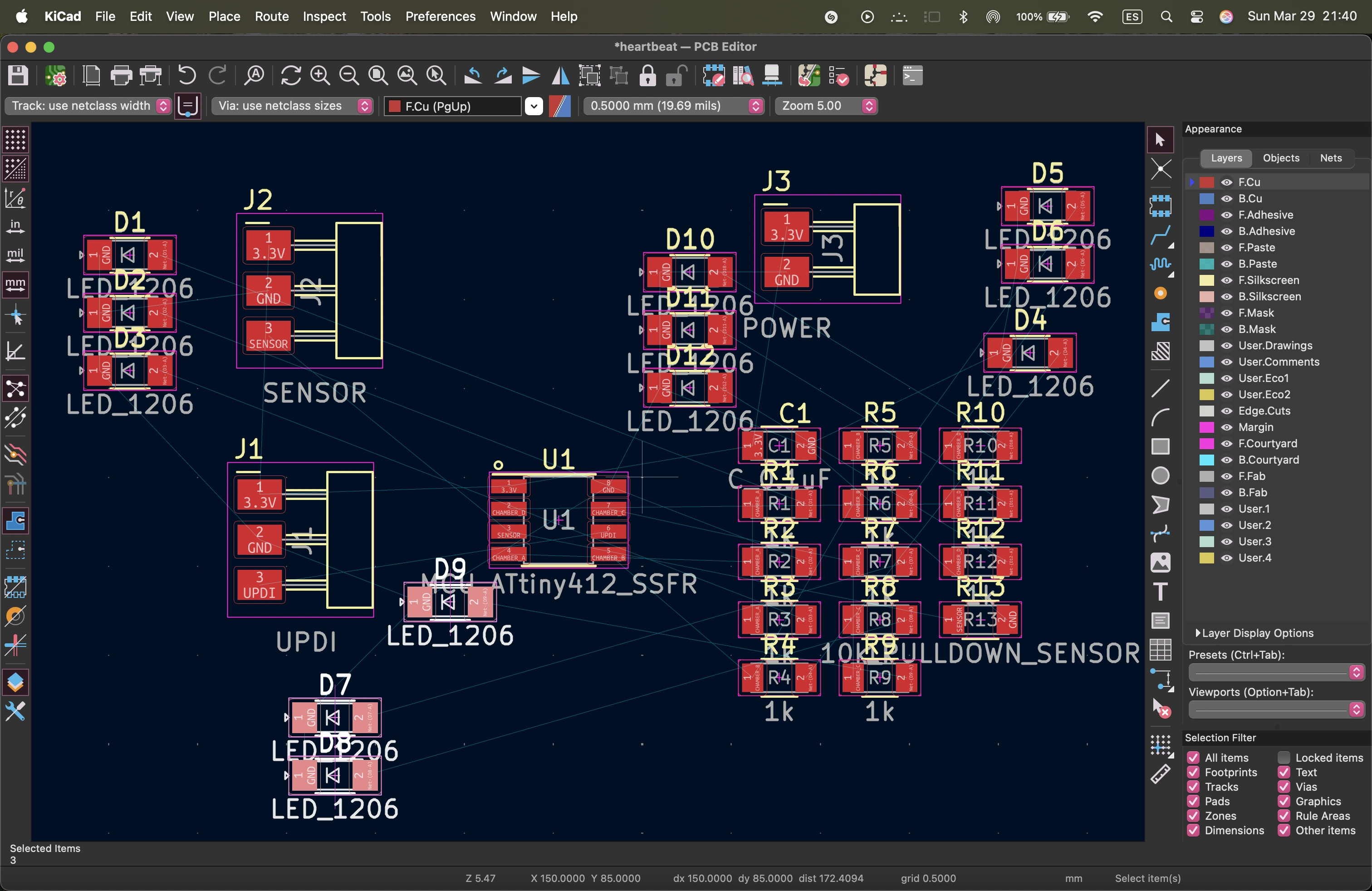
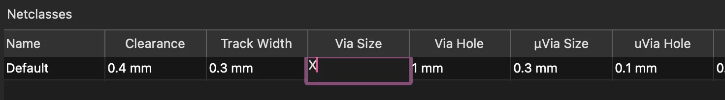
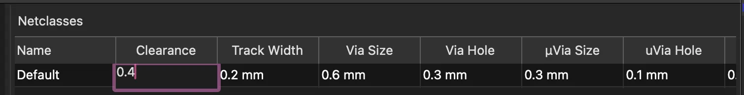
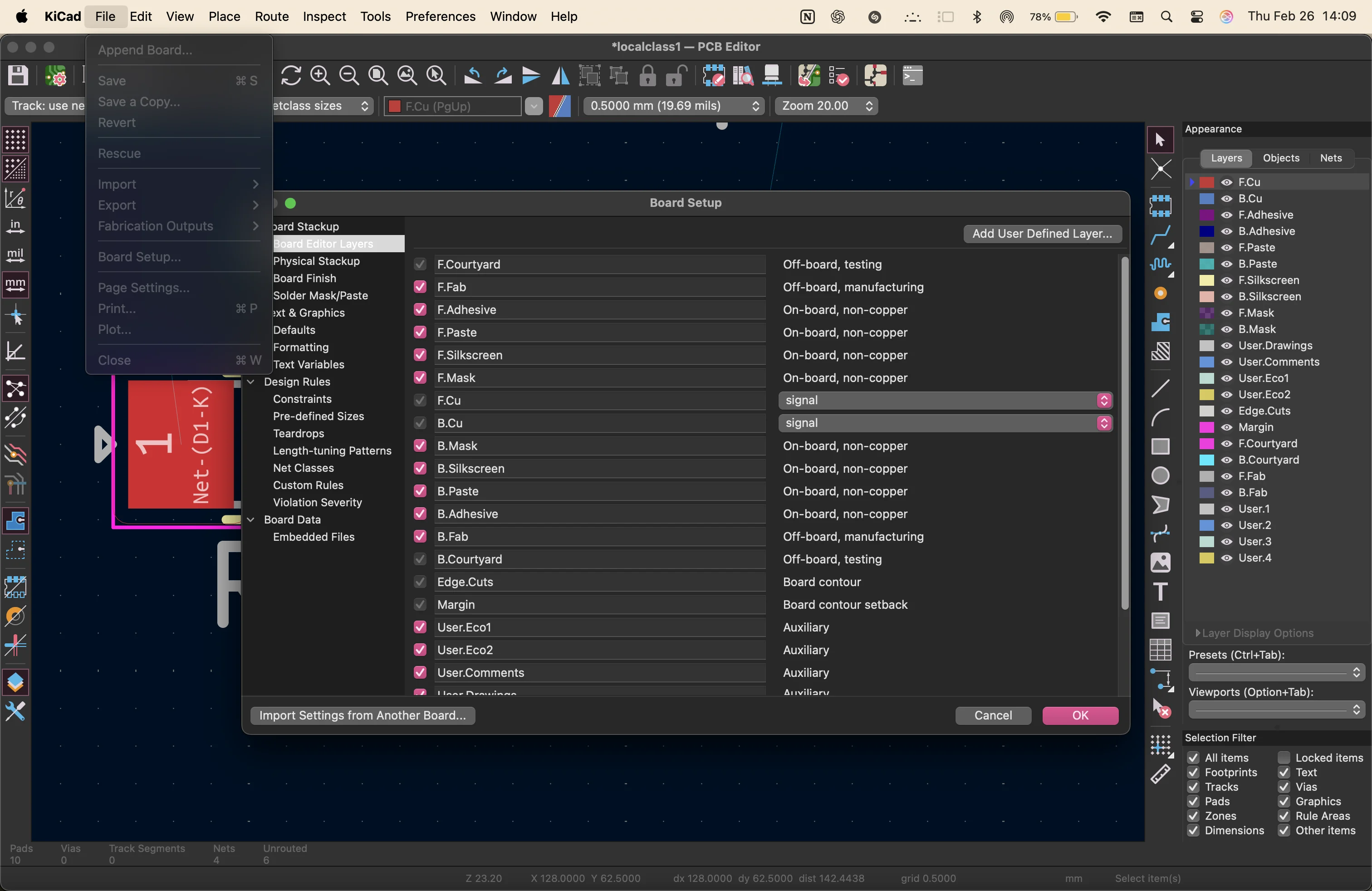
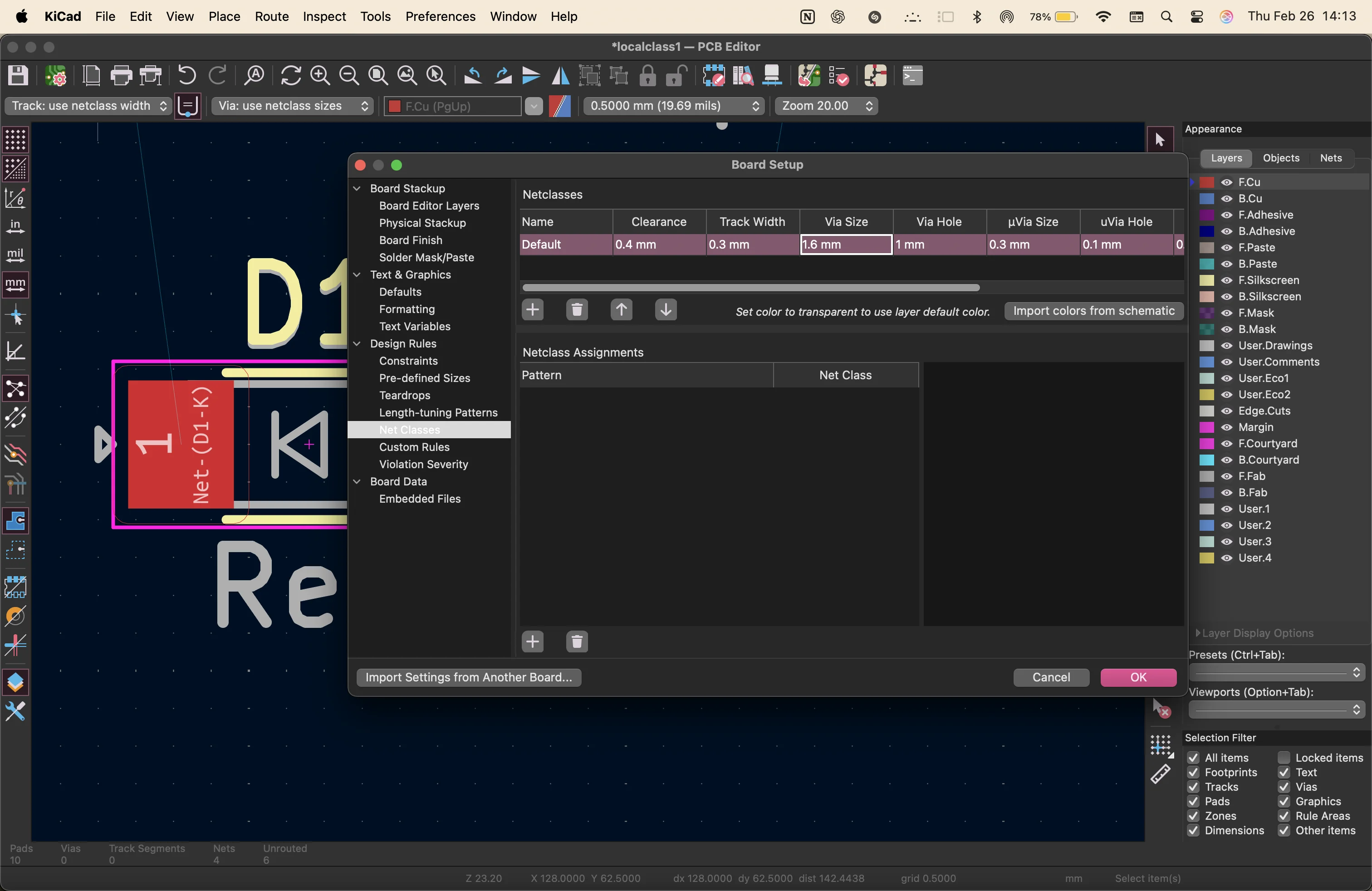
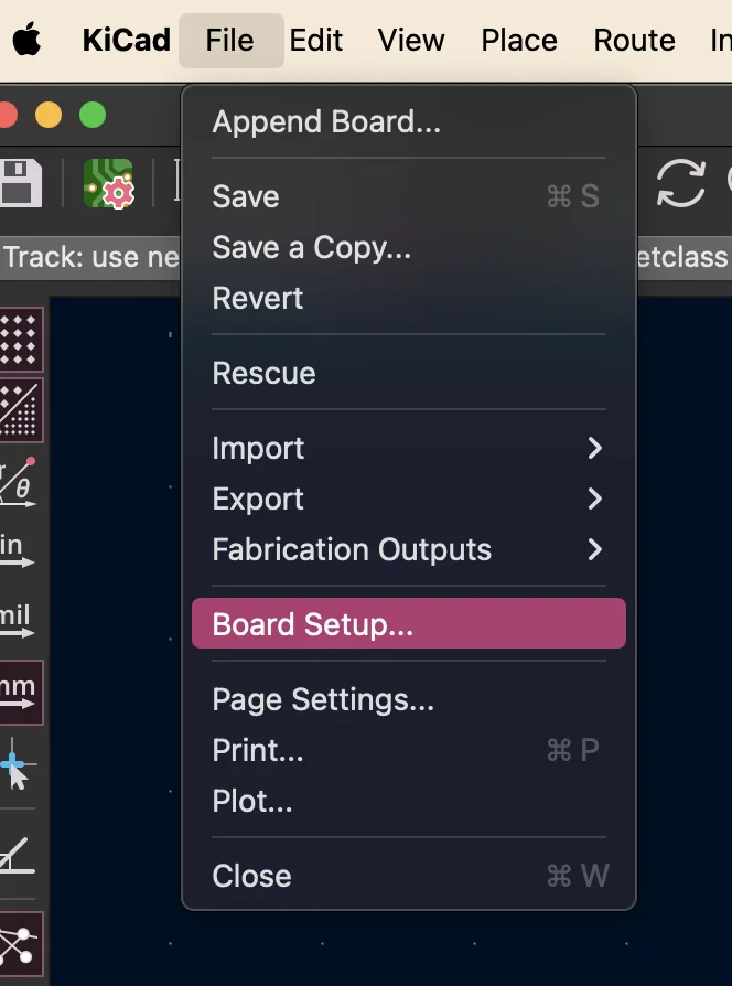
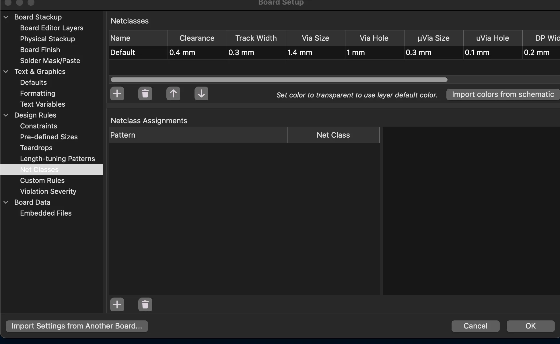
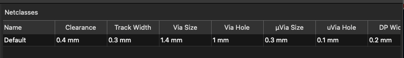
first i start by changing the net classes inside the board setup settings to match the machine we will be using for milling later: the Roland-SRM
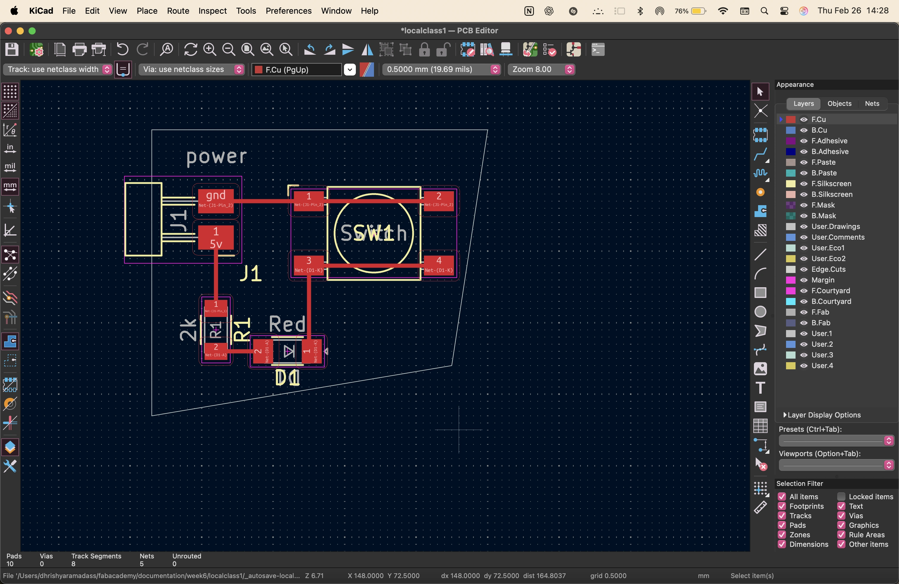
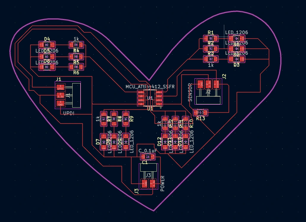
i arrange the elemets into the shape of a heart
i then go into figma to draw a vector outline of the heart shape
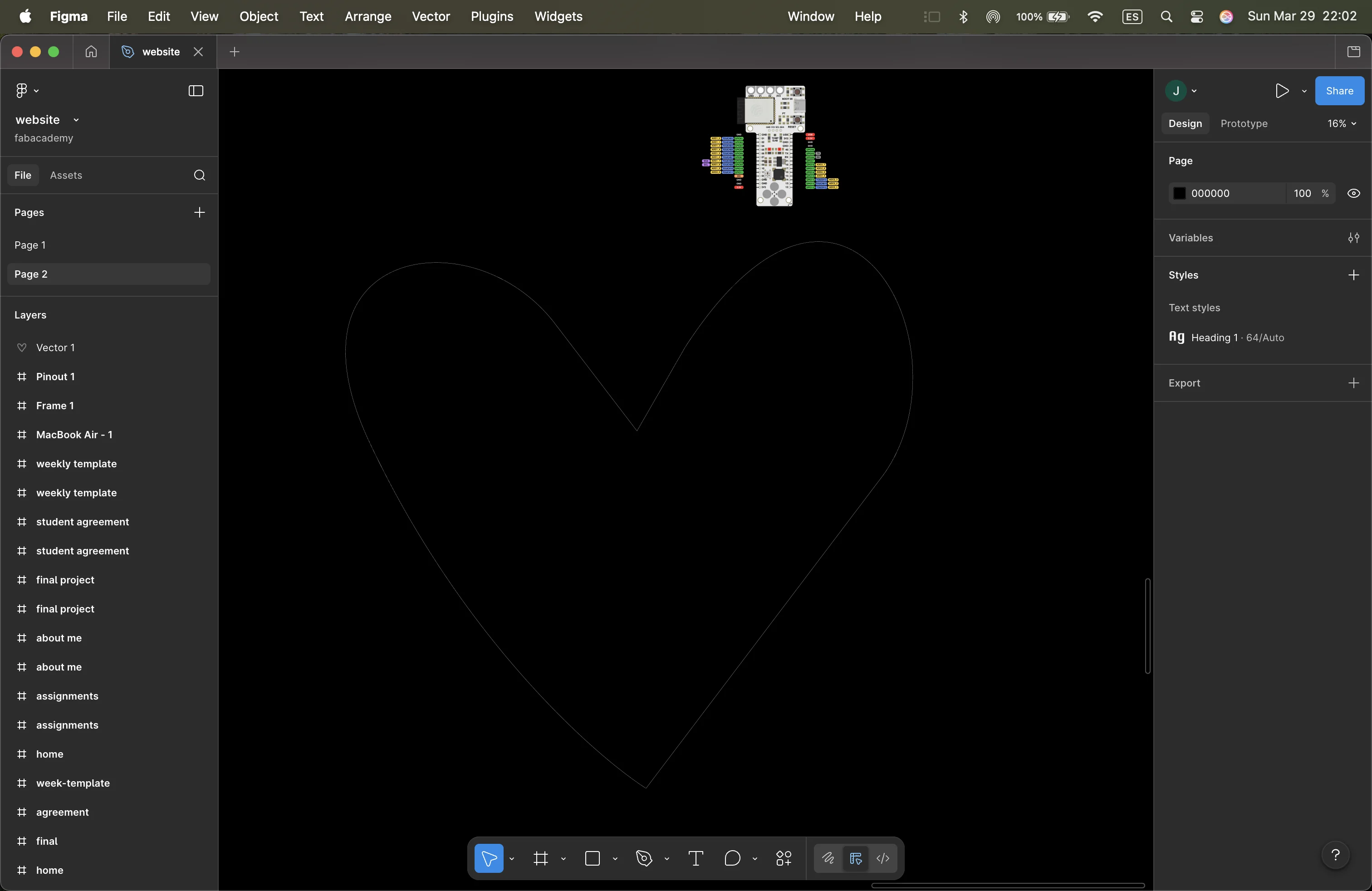
i export this heart as an svg and import into Inkscape to create outlines and make it a clean file
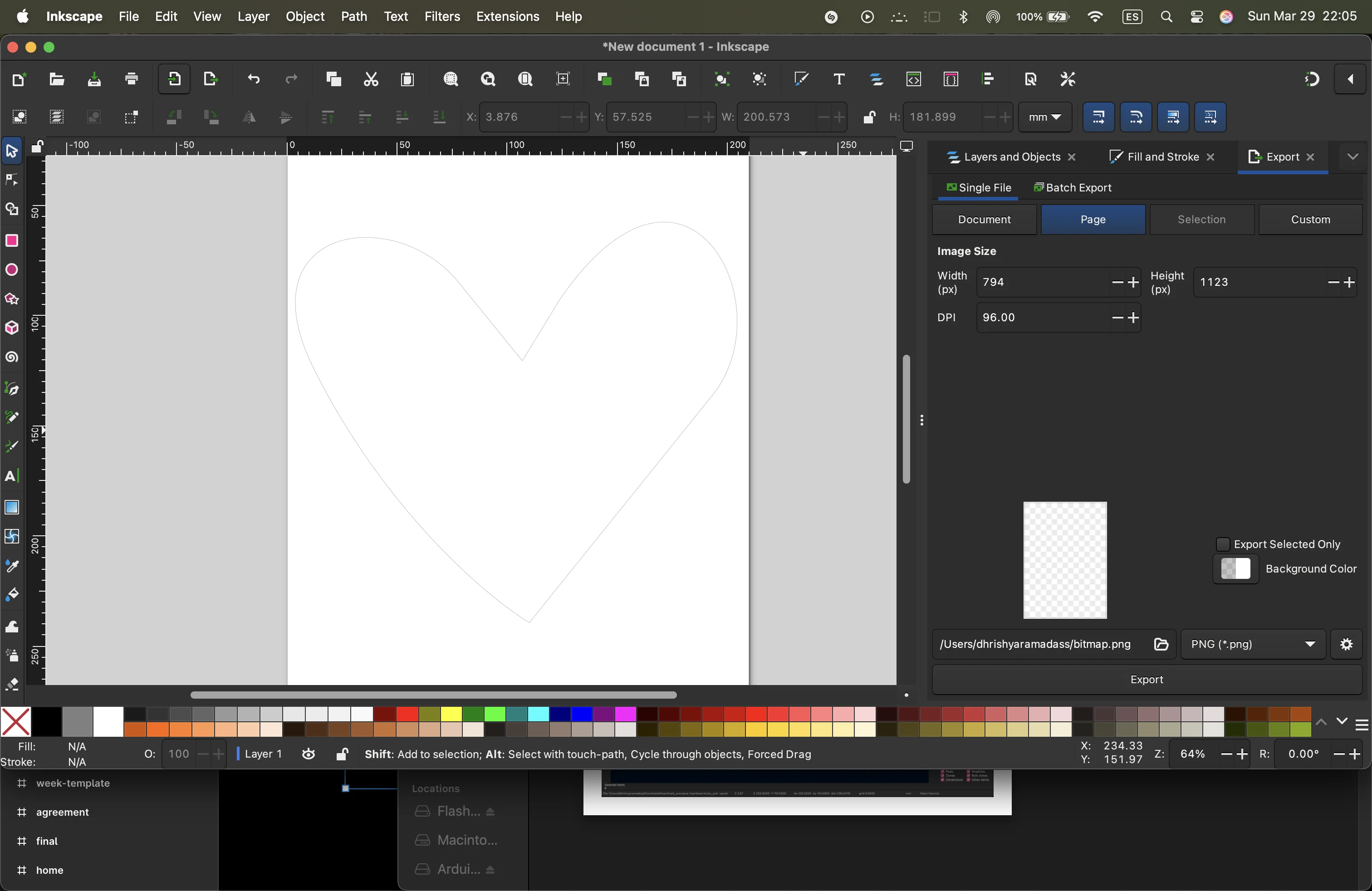
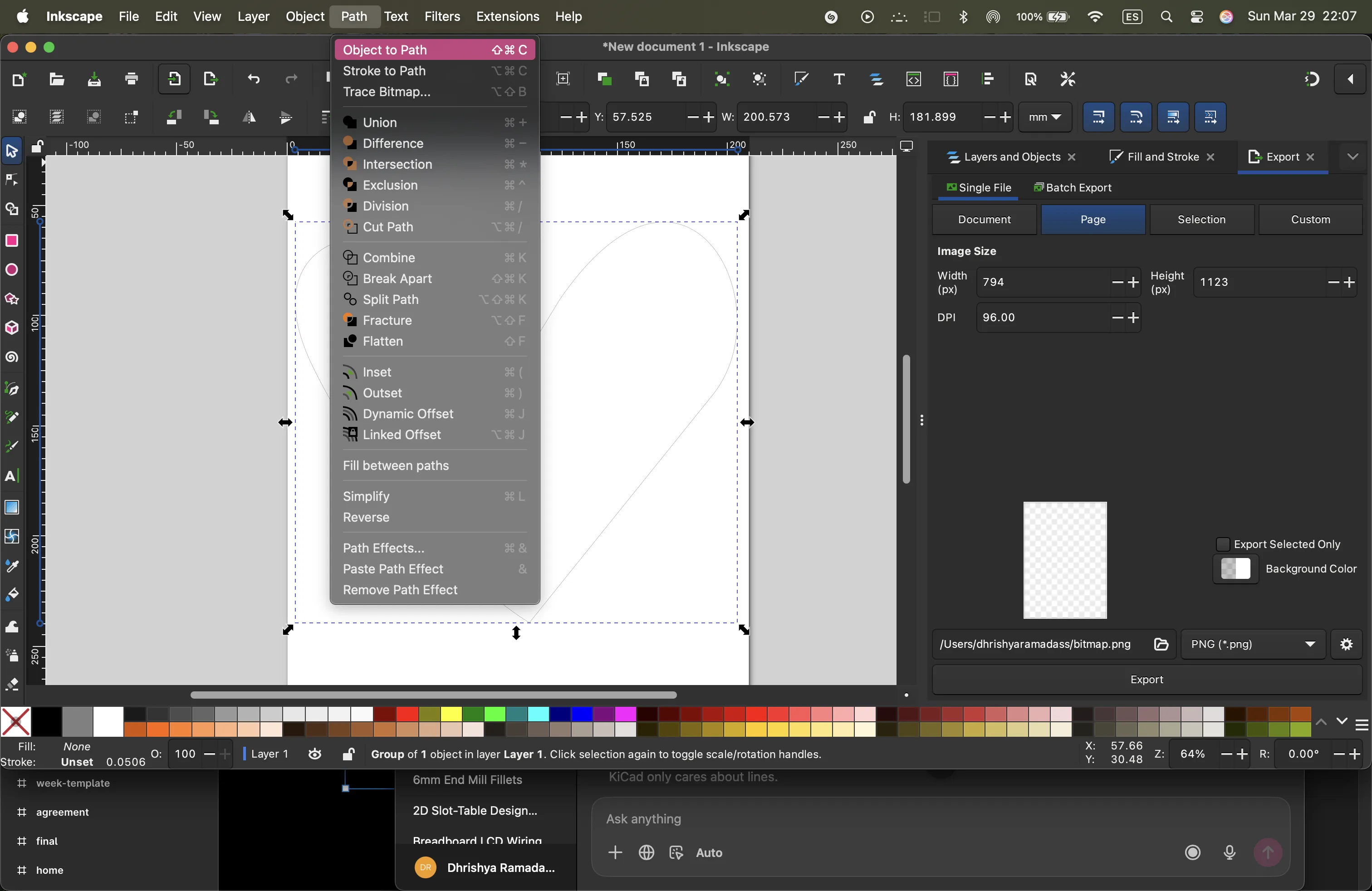
then i import this svg into kicad and use it as a guide to arrange the components in the shape of a heart
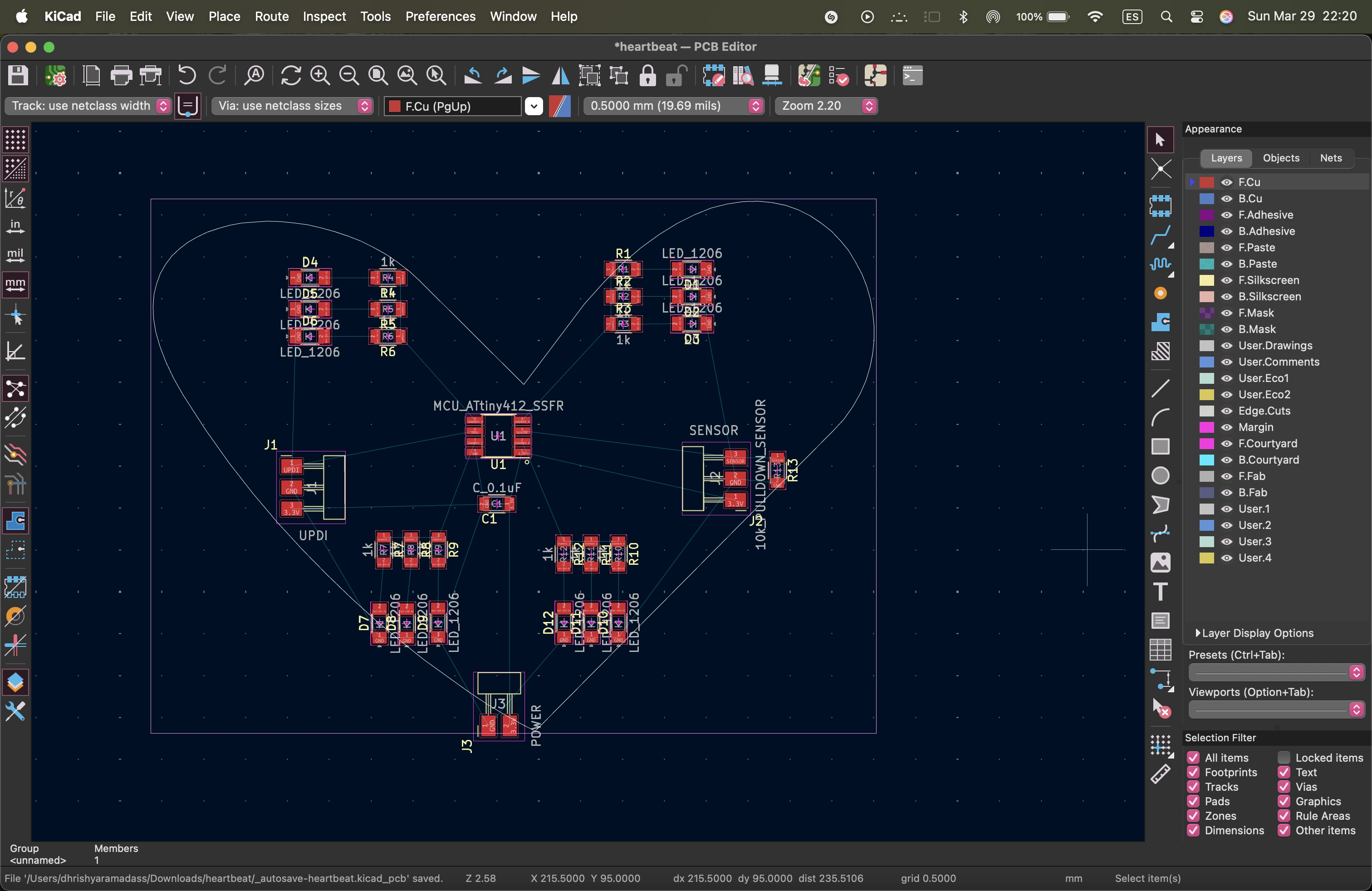
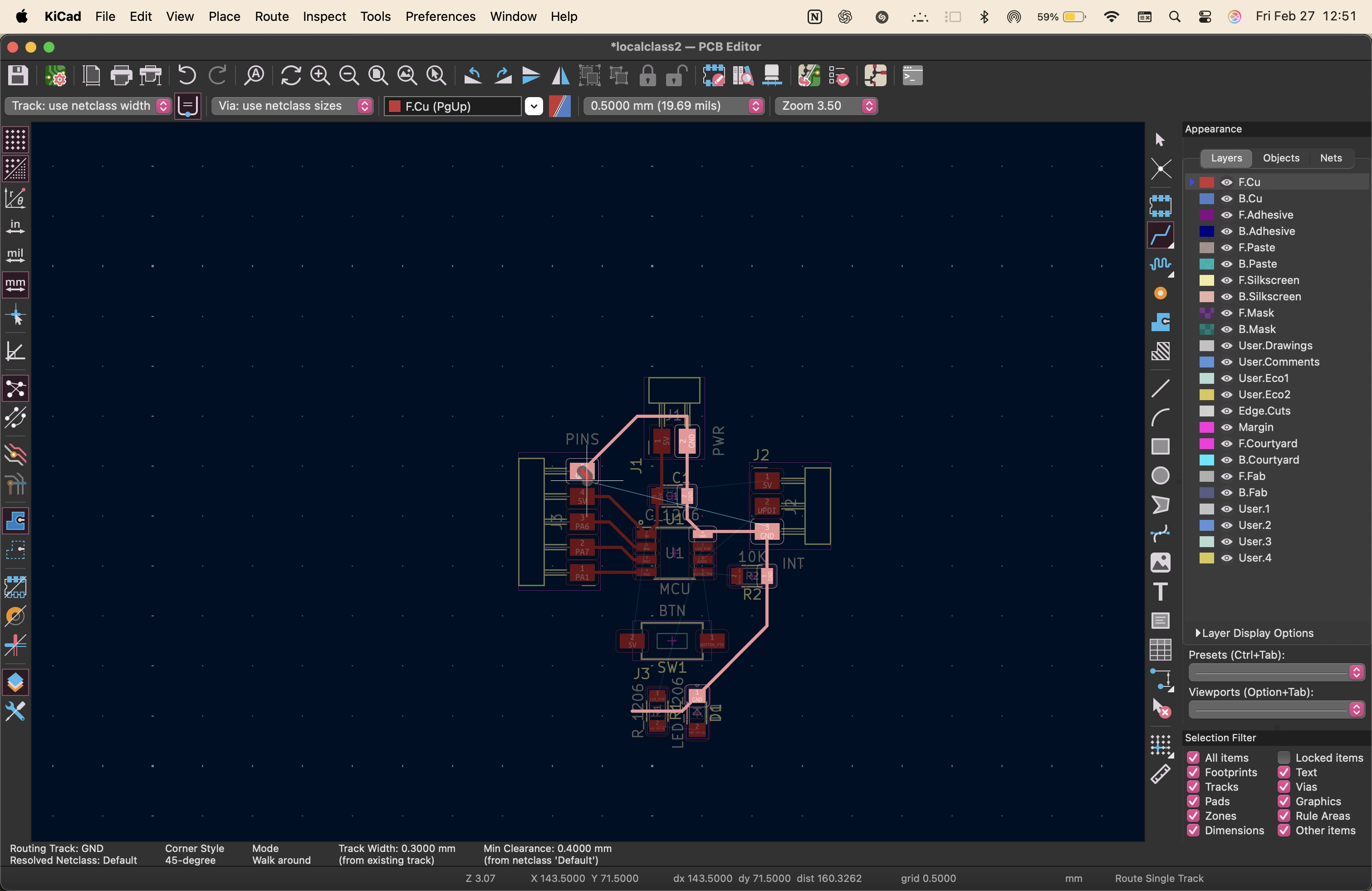
sometimes it looked like it was done but the circuit was not complete
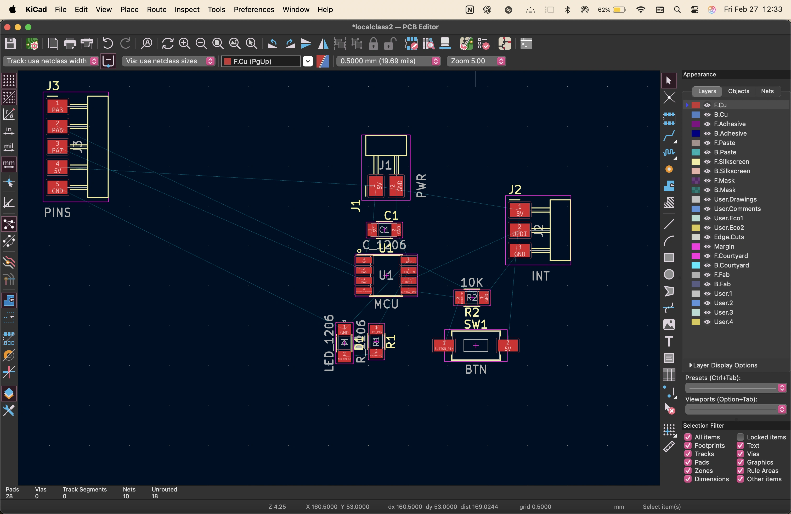
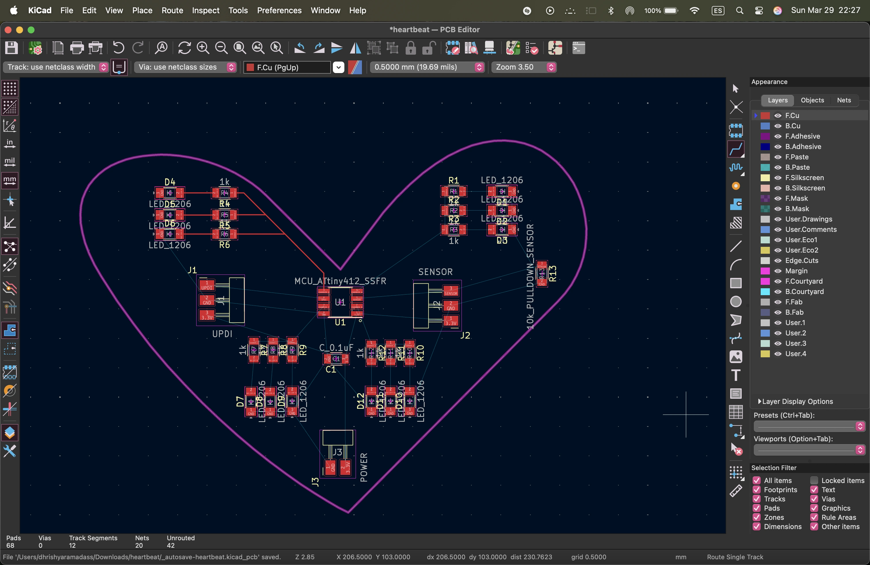
i had to rotate the components, or switch their tags in the schematic and update the pcb a few timess to figure out an orientation that worked. i also had to route some wires between the components.
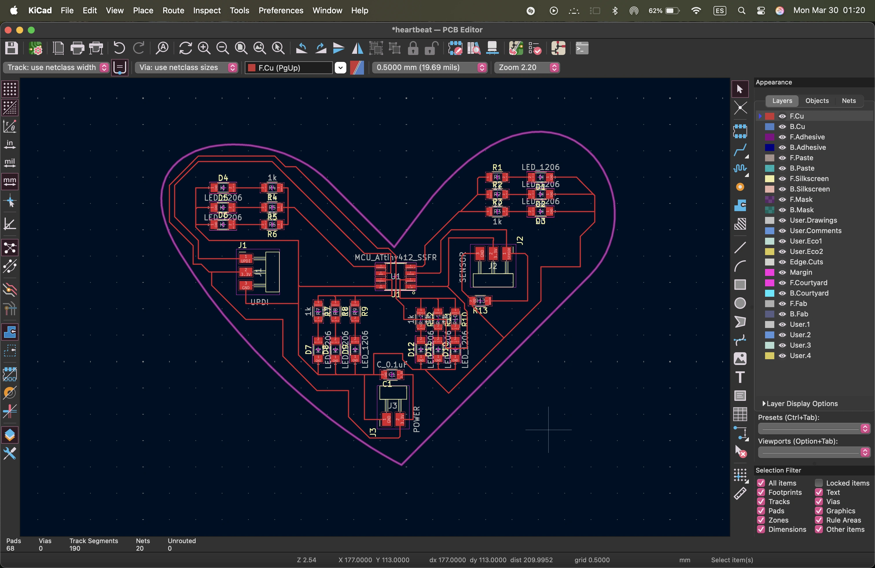
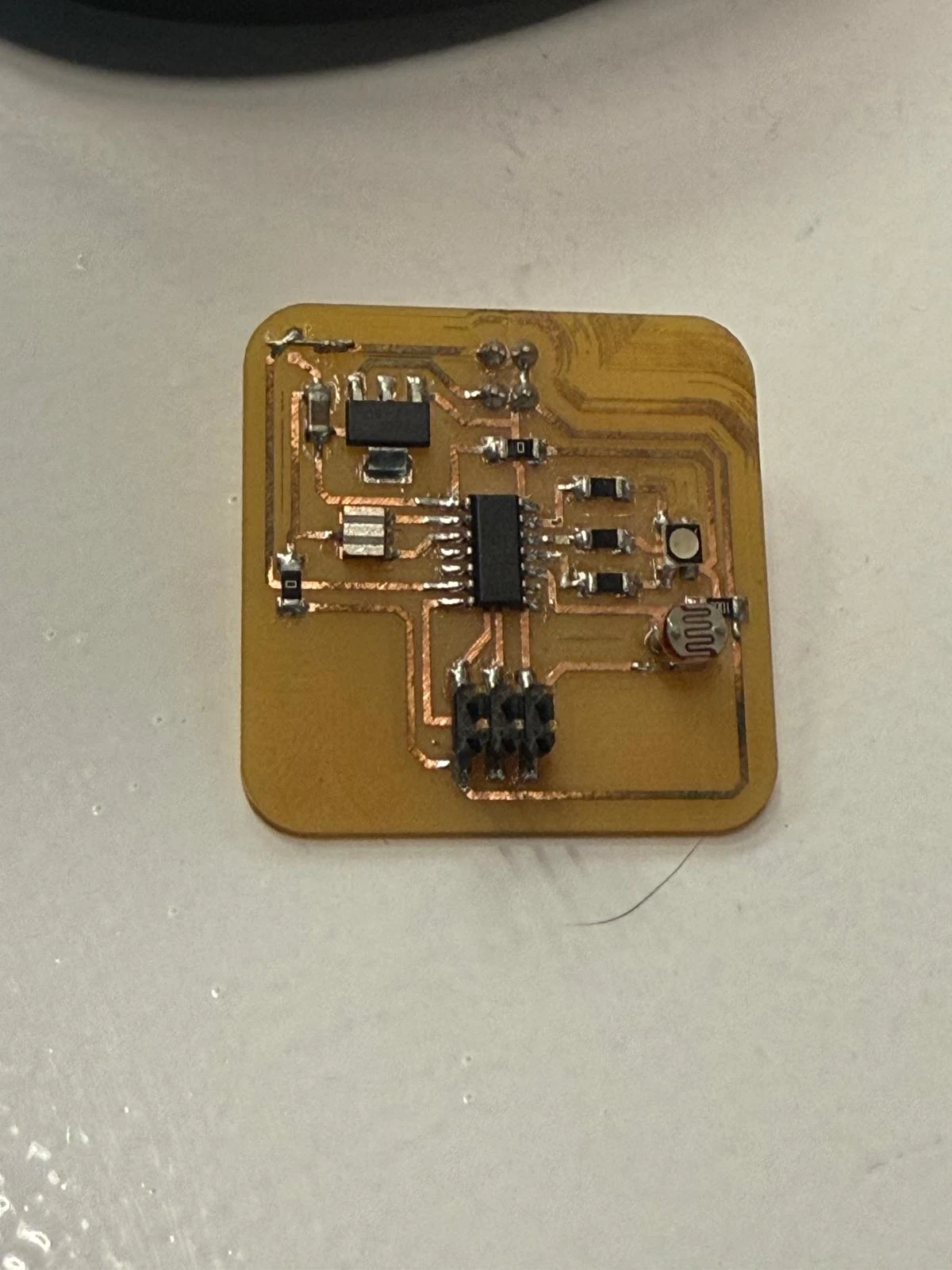
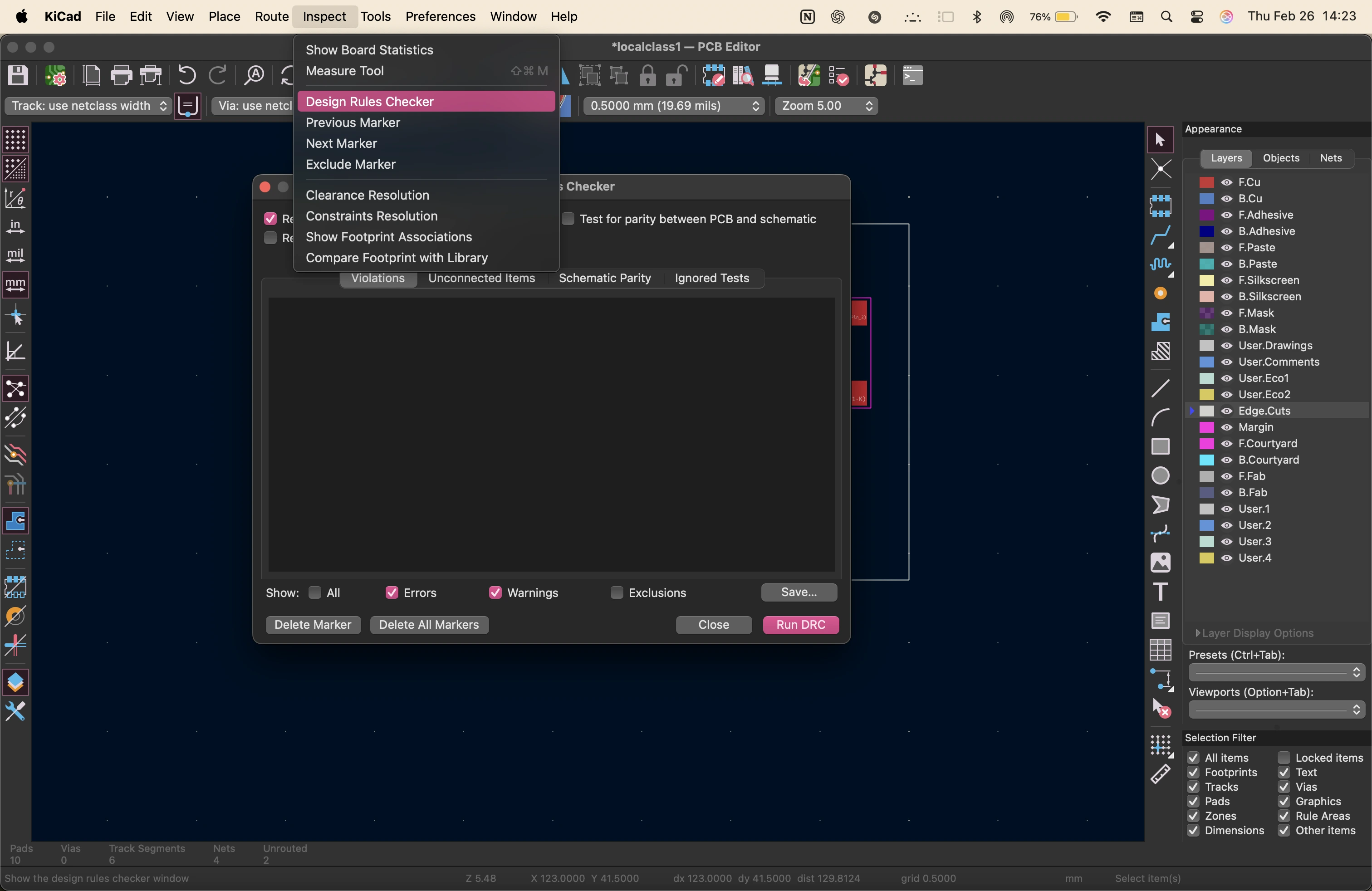
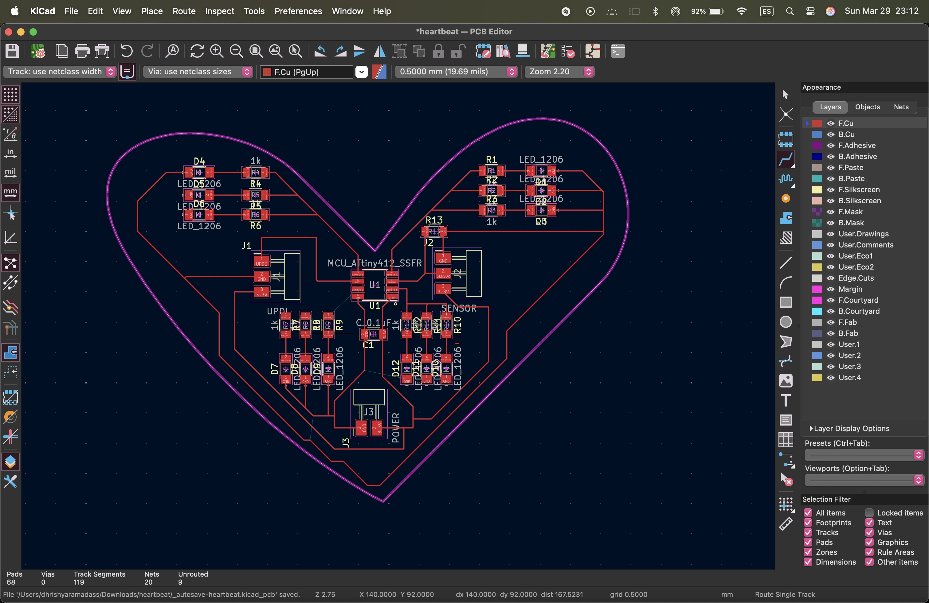
here is the final design. it is important to use the design rules checker to avoid errors and issues while fabrication.
original files
inside the Zip folder, you will find the kicad file, the schematic and the pcb layout files.
personal reflections
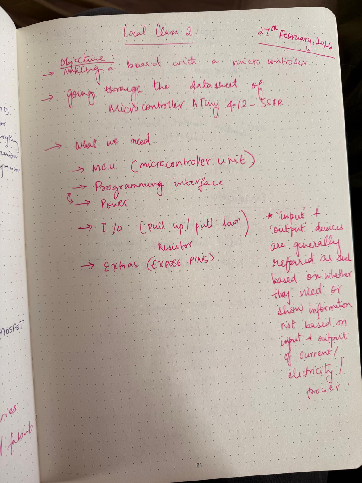
For this week, we explored the parts of a PCB and what generally goes into a simple input-output board. Every usable board we make or use, like Arduinos, Raspberry Pis, and custom boards, all have these basic systems that we need.
The microcontroller unit acts as the brain. I am going to be using the ESP32. We also need a programming interface, which I will use through the UART pin. It is a way to talk to the microcontroller unit.
Input-output devices use the GPIO pins. I would say these are kind of like the mouth and eyes, like sensors and expressors. We also need power, so a 2-pin power connection to be able to use 5 volts and 3.3 volts, and connector pins as a way to expand and use the board further if needed.
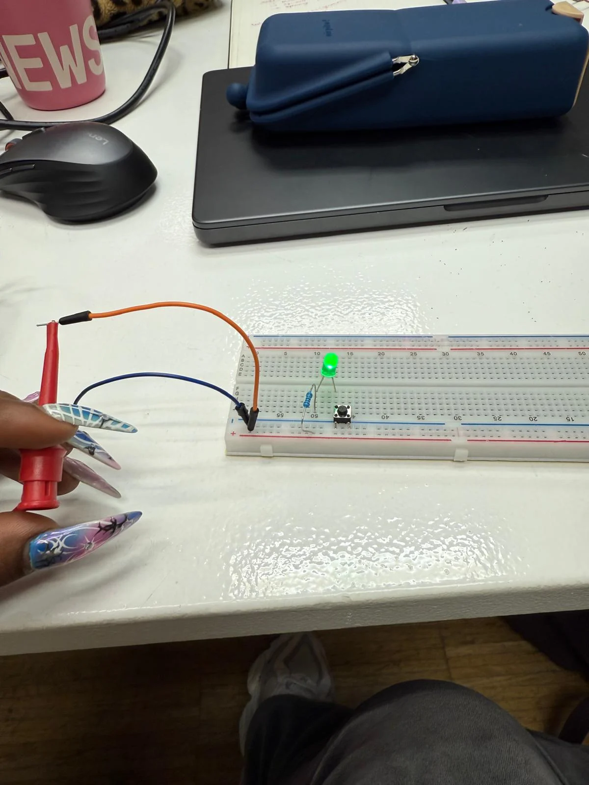
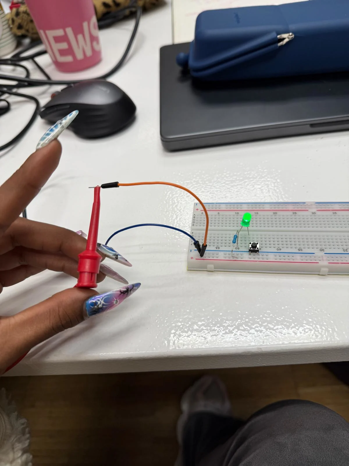
Along with lights, buttons, screens, and sensors, we also need to add pull-up and pull-down resistors to protect from surges and loose pins.
I understand PCBs much better now and how to use Arduino to communicate with them. I still need to use AI to generate any code more complex than blinking lights, but I will practice more and write my final project code without using artificial intelligence. That is my goal.
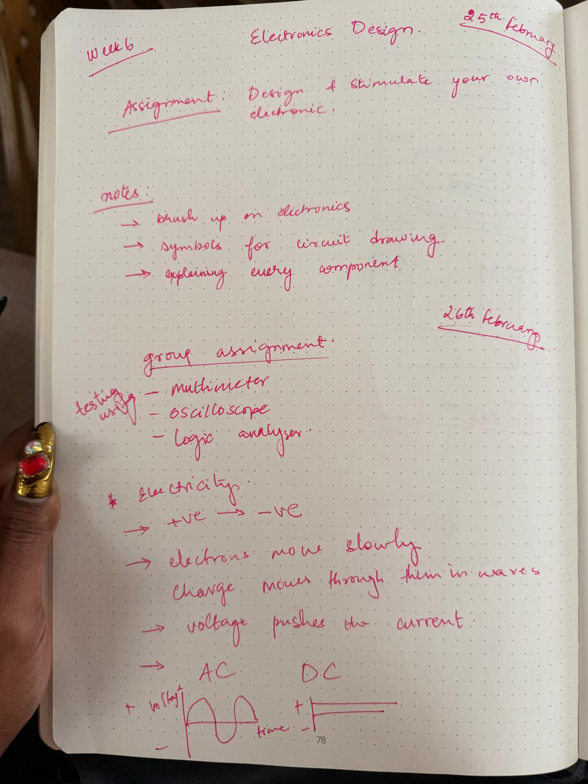
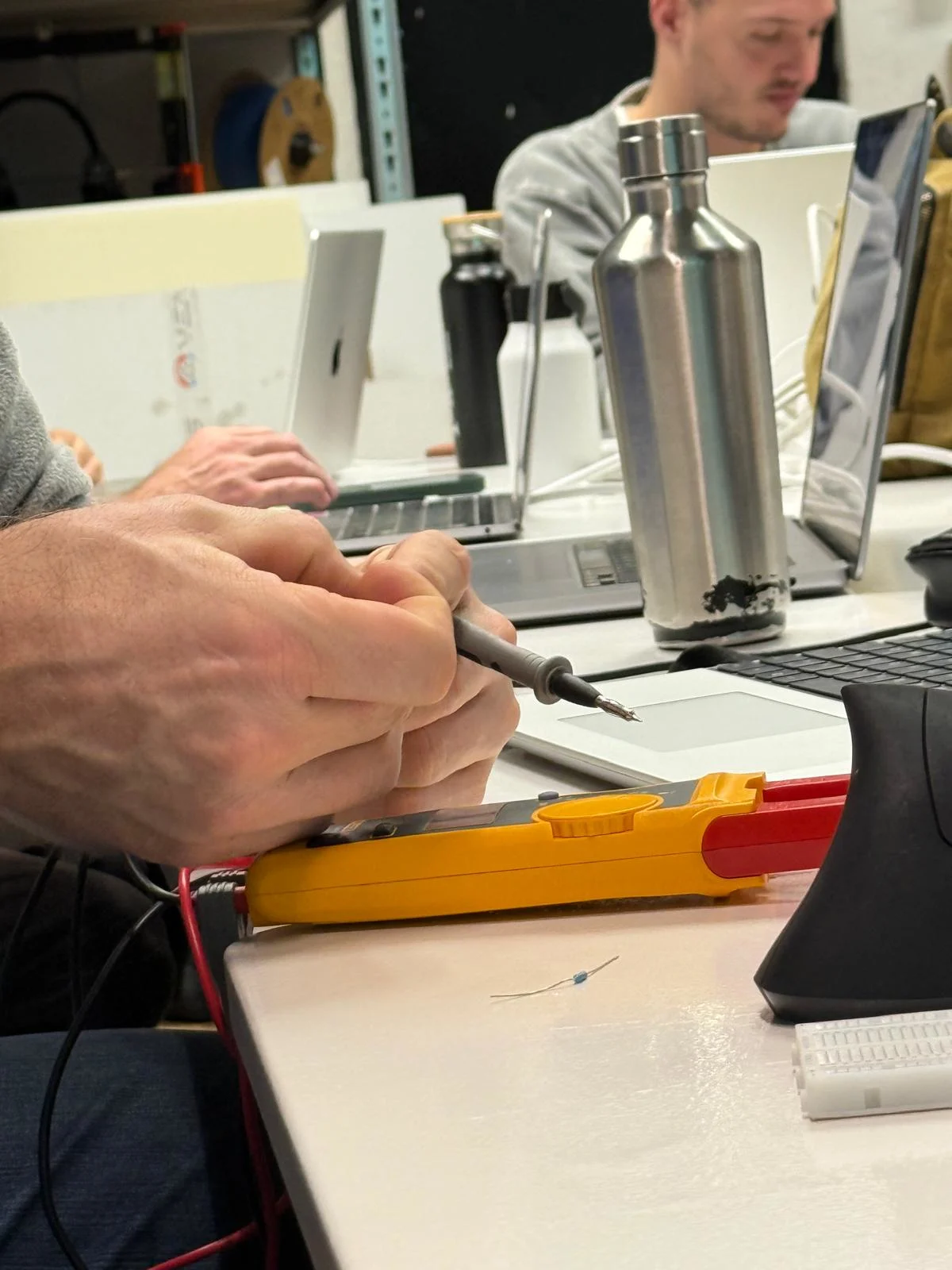
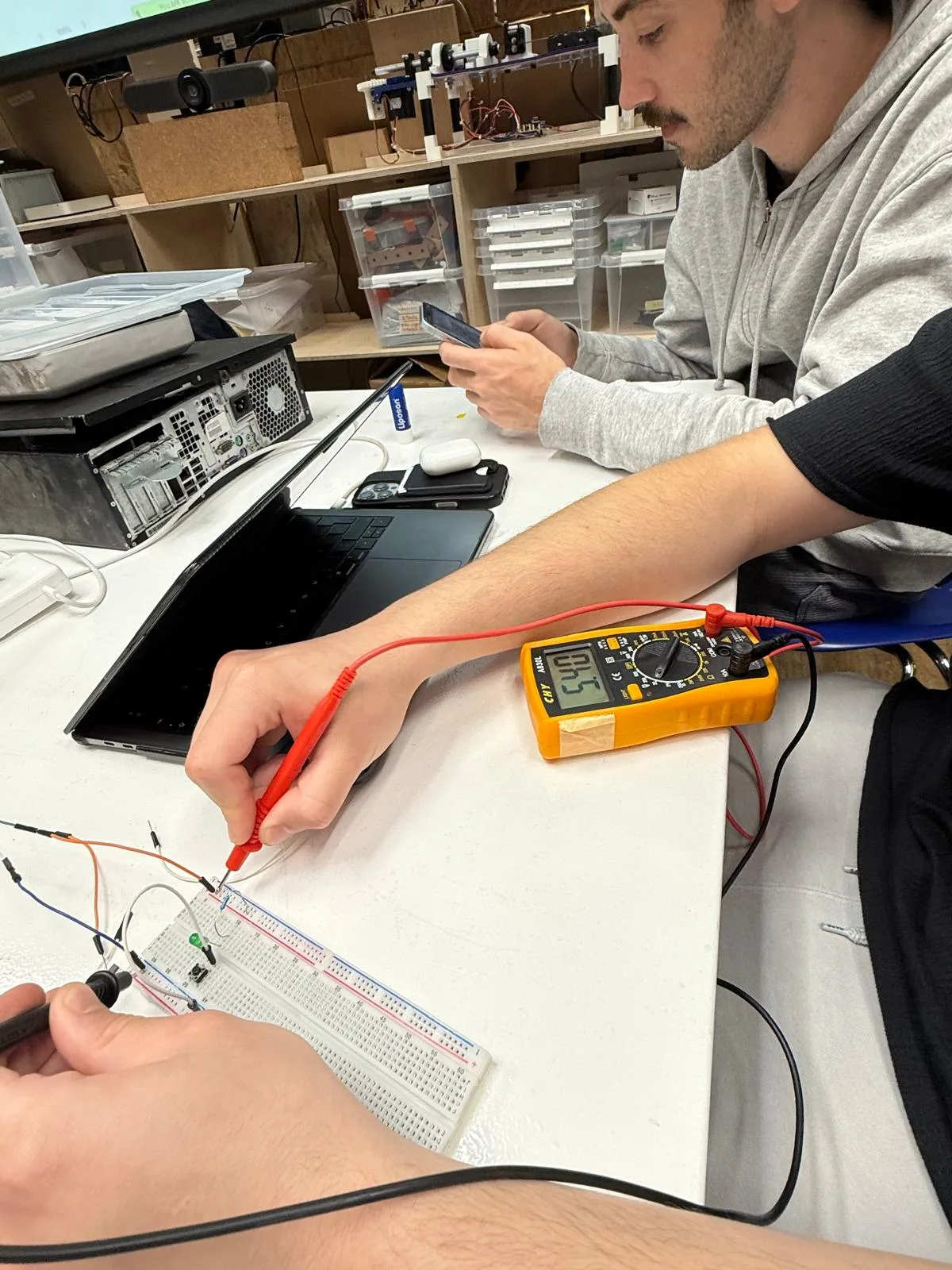
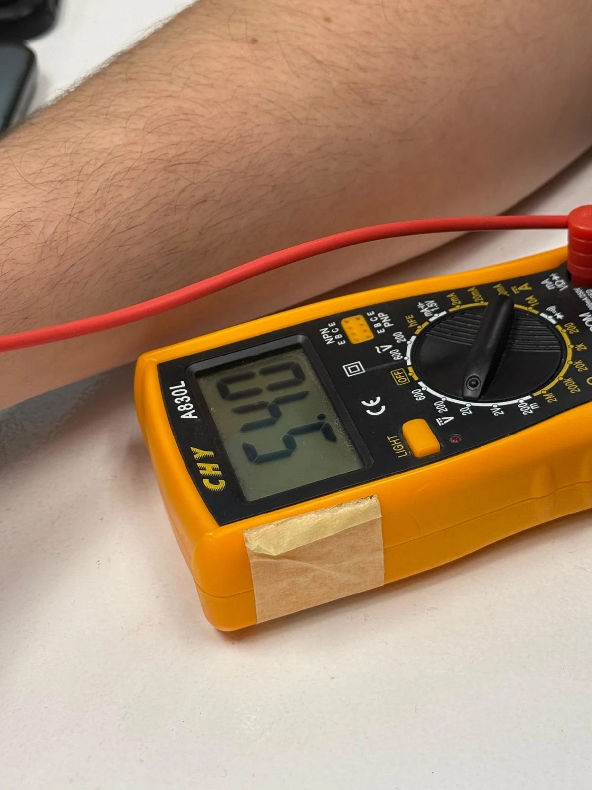
We also learned the importance of understanding the components we use and testing them with oscilloscopes, multimeters, and logic analyzers to understand power usage, current flow, and other necessary factors that will decide the resistors and capacitors that we need for the board.
We also understand the specific functions of pins in the microcontroller unit to match the purpose of each part of the system. It was interesting to observe how electricity behaves inside a circuit and the ways needed to measure and create safety measures like decoupling and the concept of pull-down resistors.
Multimeters are good for debugging circuits and are my new best friend. It takes an initial effort to understand how to use them, and they turn out to be the most useful thing during the whole process.
Group assignment
here is the link to the group assignment page Group Assignment week 6
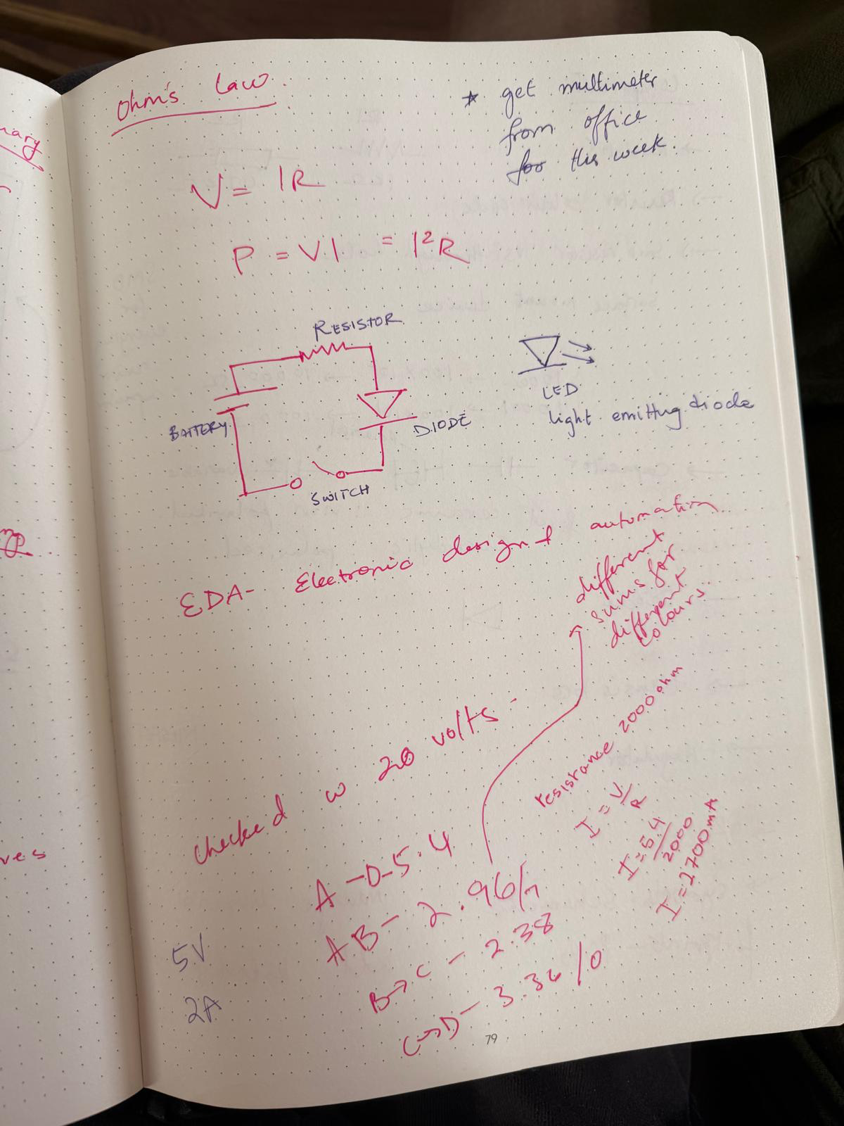
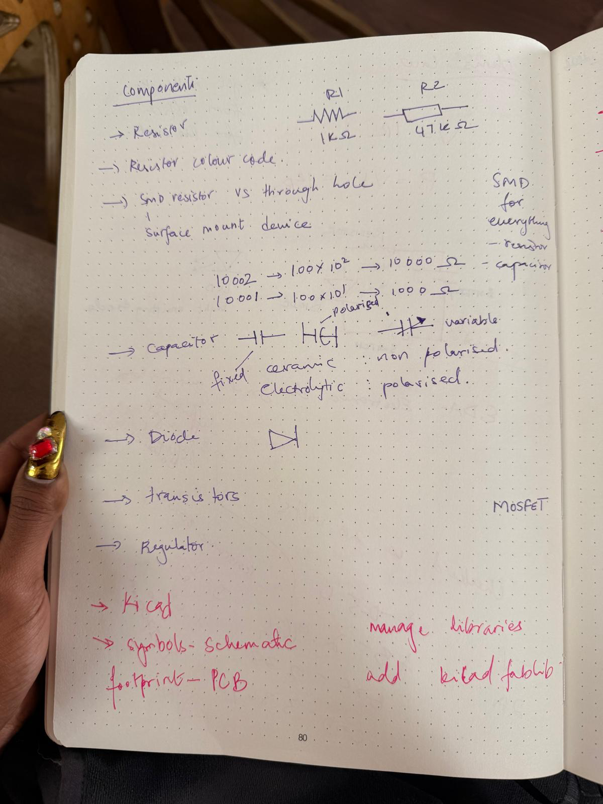
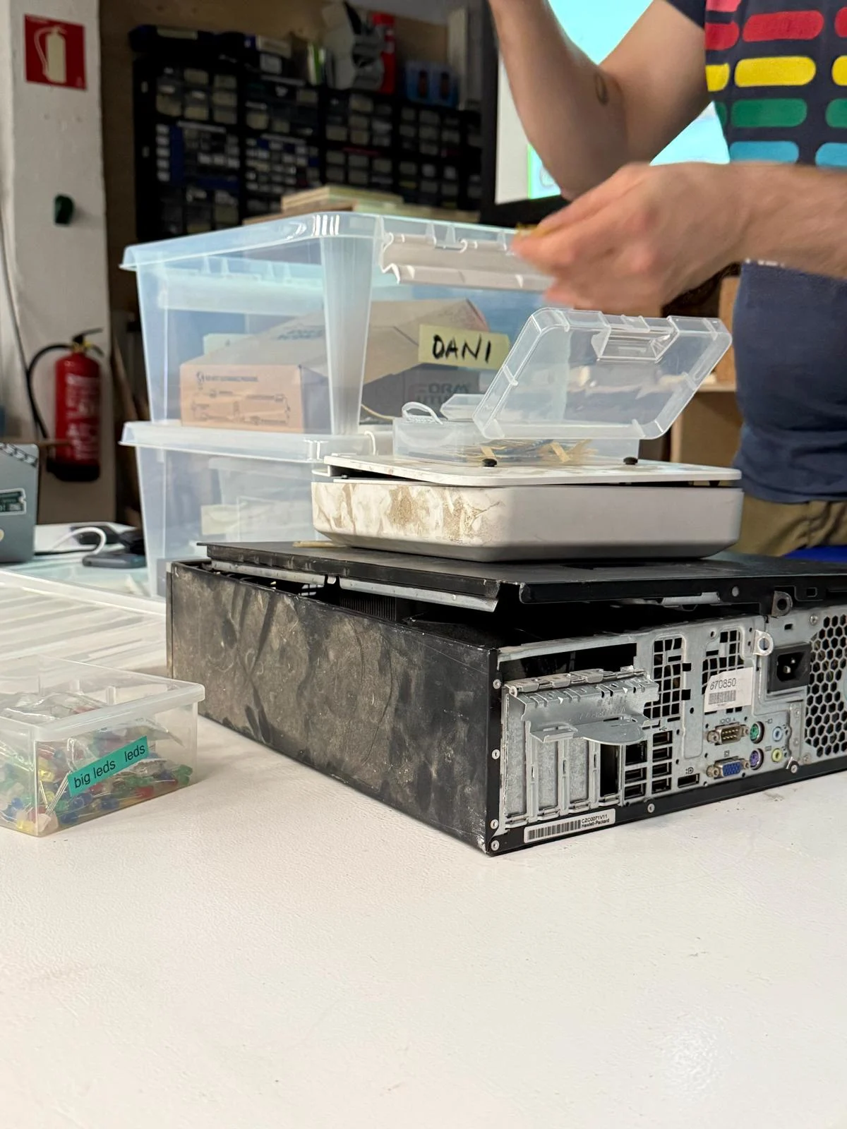
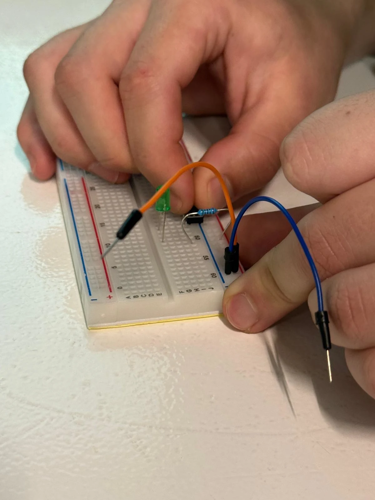
Notes
images from the local class